EP0332765A2 - Graphical input/output system and method - Google Patents
Graphical input/output system and method Download PDFInfo
- Publication number
- EP0332765A2 EP0332765A2 EP88121897A EP88121897A EP0332765A2 EP 0332765 A2 EP0332765 A2 EP 0332765A2 EP 88121897 A EP88121897 A EP 88121897A EP 88121897 A EP88121897 A EP 88121897A EP 0332765 A2 EP0332765 A2 EP 0332765A2
- Authority
- EP
- European Patent Office
- Prior art keywords
- pattern
- determining means
- determining
- locus
- traverse
- Prior art date
- Legal status (The legal status is an assumption and is not a legal conclusion. Google has not performed a legal analysis and makes no representation as to the accuracy of the status listed.)
- Granted
Links
Images


Classifications
-
- G—PHYSICS
- G06—COMPUTING; CALCULATING OR COUNTING
- G06V—IMAGE OR VIDEO RECOGNITION OR UNDERSTANDING
- G06V10/00—Arrangements for image or video recognition or understanding
- G06V10/10—Image acquisition
-
- G—PHYSICS
- G06—COMPUTING; CALCULATING OR COUNTING
- G06F—ELECTRIC DIGITAL DATA PROCESSING
- G06F3/00—Input arrangements for transferring data to be processed into a form capable of being handled by the computer; Output arrangements for transferring data from processing unit to output unit, e.g. interface arrangements
- G06F3/01—Input arrangements or combined input and output arrangements for interaction between user and computer
- G06F3/048—Interaction techniques based on graphical user interfaces [GUI]
- G06F3/0487—Interaction techniques based on graphical user interfaces [GUI] using specific features provided by the input device, e.g. functions controlled by the rotation of a mouse with dual sensing arrangements, or of the nature of the input device, e.g. tap gestures based on pressure sensed by a digitiser
- G06F3/0488—Interaction techniques based on graphical user interfaces [GUI] using specific features provided by the input device, e.g. functions controlled by the rotation of a mouse with dual sensing arrangements, or of the nature of the input device, e.g. tap gestures based on pressure sensed by a digitiser using a touch-screen or digitiser, e.g. input of commands through traced gestures
- G06F3/04883—Interaction techniques based on graphical user interfaces [GUI] using specific features provided by the input device, e.g. functions controlled by the rotation of a mouse with dual sensing arrangements, or of the nature of the input device, e.g. tap gestures based on pressure sensed by a digitiser using a touch-screen or digitiser, e.g. input of commands through traced gestures for inputting data by handwriting, e.g. gesture or text
-
- G—PHYSICS
- G06—COMPUTING; CALCULATING OR COUNTING
- G06F—ELECTRIC DIGITAL DATA PROCESSING
- G06F3/00—Input arrangements for transferring data to be processed into a form capable of being handled by the computer; Output arrangements for transferring data from processing unit to output unit, e.g. interface arrangements
- G06F3/01—Input arrangements or combined input and output arrangements for interaction between user and computer
- G06F3/048—Interaction techniques based on graphical user interfaces [GUI]
- G06F3/0484—Interaction techniques based on graphical user interfaces [GUI] for the control of specific functions or operations, e.g. selecting or manipulating an object, an image or a displayed text element, setting a parameter value or selecting a range
- G06F3/04845—Interaction techniques based on graphical user interfaces [GUI] for the control of specific functions or operations, e.g. selecting or manipulating an object, an image or a displayed text element, setting a parameter value or selecting a range for image manipulation, e.g. dragging, rotation, expansion or change of colour
Definitions
- the present invention relates to a context-base input/output system and, more particularly, to a context-base input/output system for inputting a manually drawn sketch to a computer to convert it into a geometrically defined pattern and display it.
- pattern input to the computer is accomplished by means of an electronic pen, a digitizer, a mouse or the like after either a menu (i.e., a table indicating the functions) on the screen of a CRT or a tablet menu on a tablet has been selected.
- a menu i.e., a table indicating the functions
- the function to display the circle is selected from the menu.
- a data corresponding to a central point of the circle and one point on its circumference are registered at a predetermined position of the tablet by means of the electronic pen.
- the computer executes graphic processing to display the circle according to the input data on the CRT.
- difference from the foregoing method is limited to a point that the selection of function from the menu is executed on the tablet.
- the aforementioned methods of selecting the graphic processing function according to the menues troubled by problems that a number of steps of selecting the function from the menu is more than a method of manually drawing a segment or circle directly on a paper by writing means so that they are not only troublesome but also felt with a physical disorder, thus making it difficult to use the tool.
- the method of inputting the data is executed by inputting the data of specific points and is followed by the feeling of a physical disorder because operations are different from those in case the pattern is manually drawn.
- the present invention is conceived to solve the above-specified problems and has an object to provide a context-base input/output system capable of inputting a physical data, as if a pattern were to be drawn on a paper by writing means, to display a pattern thereof.
- a context-base input/output system including input means having an electronic pen and a tablet for converting a locus of the electronic pen on a tablet into dot data to input them; first determining means based on the input dot data for determining what of at least a segment, circle and arc is expressed by the locus; display means based on the determination result of the first determining means for displaying a pattern expressed by the locus in a display apparatus; memory means for memorizing graphic processing commands which correspond to a plurality of predetermined patterns, respectively; second determining means, based on the determination result of the first determining means for determining whether or not the predetermined patterns are expressed by the locus: and processing means based on the determination result of the second determining means for graphic processing in response to the commands corresponding to the predetermined patterns expressed by the locus.
- the input means of the present invention is composed of the electronic pen and the tablet, and the locus of the electronic pen on the tablet is converted into dot data before it is registered.
- the data of a manually drawn pattern are converted into the dot data and inputted by drawing the pattern on the tablet by the electronic pen.
- the first determining means is based upon the inputted dot data for determining what of at least the segment, circle and arc is expressed by the locus of the electronic pen on the tablet.
- the display means is based on the determination result of the first determining means for displaying on the display apparatus the pattern expressed by the locus of the electronic pen.
- the first determining means what pattern is expressed, that is to say, what geometric pattern the manually drawn pattern resembles.
- the manually drawn pattern is converted into the geometrically defined pattern and displayed on the display apparatus.
- the pattern can be inputted or outputted without using any menu.
- the memory means memorizes or stores the graphic processing commands corresponding to a plurality of predetermined patterns, respectively.
- the second determining means is based on the determination result of the first determining means for deter mining whether or not the predetermined patterns are expressed by the locus of the electronic pen.
- the processing means is based on the determination result of the second determining means for graphic processing in response to the command corresponding to the predetermined drawing expressed by the locus of the electronic pen, if so expressed.
- the graphic processing command can be designated by drawing a specific pattern without using any menue.
- the pattern will be herein termed to be a set of points, lines and planes as well as letters and symbols.
- FIG. 2 is a schematic view showing the embodiment, in which a graphic processing computer 10 is composed of a CPU, a ROM and a RAM.
- the computer 10 is connected with a CRT 12, a keyboard 14 and a tablet 16.
- the tablet 16 is connected with an electric pen 18, and a tip of the electric pen 18 is movable on and in contact with a surface of the tablet 16 to convert a moving locus into dot data, which are then inputted to the computer 10.
- the computer 10 has the ROM stored in advance with both the program of a graphic processing control routine, as will be described hereinafter. and commands corresponding to specific patterns.
- the control routine will be described in the following.
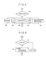
- Step 34 it is determined which the data are inputted from the tablet 16 or the keyboard 14. If it is determined that the data are inputted from the keyboard 14, the keyboard inputting operation is executed at Step 36, as will be described in more detail with reference to Fig. 5.
- the pattern recognition is executed at Step 38.
- the detail of this pattern recognition will be described hereinafter with reference to Fig. 3.
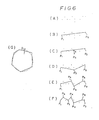
- the dot data inputted from the tablet 16 takes the shape, as shown in Fig. 6(A), for example.
- Step 60 a formula expressing a straight line passing through the start point P1 and the end point P2 of the dot data is arithmetically determined (as shown in Fig. 6(B)).
- Step 62 one remotest point P3 from that a straight line is selected, and the distance d between the remotest point P3 and the straight line is arithmetically determined (as shown in Fig. 6(C)).
- the distance d is compared with a parameter ⁇ 1.
- the remotest point P3 selected at the Step 62 is caused to substitute the start and end points at Step 68, and the routine returns to the Step 60.
- the point P3 becomes the end point with respect to the start point P1 and becomes the start point with respect to the end point P2.
- formulas of the two straight lines, as shown in Fig. 6(D) are arithmetically determined.
- the point P3 becomes a broken point of the traverse passing through the points P1, P3 and P2.
- Steps 60, 62. 64 and 68 are repeated until the distance to the remotest point becomes less than the parameter e1, so that the traverse shown in Fig. 6(F) can be formed.
- a center of a virtual circle having the circumference or arc resembling that traverse the most is determined by determining the perpendicular bisector of one traverse line forming the traverse.
- a formula of a virtual circle having the virtual center is determined, and the maximum value D of the distance between the virtual circle and the traverse is determined at Step 74 (as shown in Fig. 6(G)).
- the maximum value D of the distance and a parameter ⁇ 2 is compared. If D ⁇ 2, it is determined that the virtual circle and the traverse resemble in shape, and this traverse is recognized as the circle or arc.
- Step 100 it is determined which of the following Table the operator inputted from the tablet belongs to:
- the operator will be described in the following.
- the symbol “X” designates the operator having a command to erase, which has a function to erase the pattern element designated by an overwrite, as shown in Fig. 7(A).
- the symbol “/” designates the operator having a command to cut, which has a function to divide across the operator a pattern element designated by the overwrite, as shown in Fig. 7(B).
- the symbol “O”, which may take any shape if it is closed, designates the operator having a command to wrap, which has a function to recognize the pattern element enclosed by the closed pattern.
- the function to copy the pattern recognized by the wrapper can be obtained by combining the arrow head " - " starting from that recognized pattern.
- the function to magnify the pattern recognized by the wrapper can be obtained by combining the outward arrow head " - “ starting from the wrapper.
- the function to reduce the pattern recognized by the wrapper can be obtained by combining the inward arrow head " - “ starting from the wrapper.
- Step 100 If it is determined at the Step 100 that the operator has the command to erase, the designated pattern element is erased from the memory at Step 102. Moreover, the graphic processings, as tabulated above, are executed at Steps 104 to 110.
- Fig. 5 shows the detail of the Step 36. It is judged at Step 112 whether or not an ending function is selected from a menu displayed in the CRT. If YES, the routine shown in Fig. 1 is ended. Otherwise, the processing according to another function selected according to the menu is executed at Step 114.
- the function include change of the magnitude of the graphic processing parameter, as has been described at the Step 32, and the store, write, erase, hard copy, all clear and help.
- a center angle 8 between a horizontal line H and a vertical line V is set as a parameter. If the segment recognized by the pattern recognization is within the range of the angle e with respect to the horizontal line H or the vertical line V, it is edited to the horizontal line H or the vertical line V. As shown in Fig. 8(B), moreover, the region of a diameter d3 around the end (point) of one segment is determined in advance. If the region includes a plurality of ends of the individual segments, the ends are connected and edited again, as shown in Fig. 8(C).
- the description thus far made is directed to an example in which the pattern inputted is displayed in the CRT. If the tablet used has a display, that CRT can be omitted to accomplish the manual drawing and the pattern display can be executed in the common portion. Moreover, the description thus far made is directed to an example in which the segment, circle or arc is recognized. However, another pattern such as an ellipse may be recognized. As the operator, there may be defined and processed the movement of a pattern, the drawing of symmetric patterns and the drawing of rotation of a pattern. Still moreover, another function of processing the intersection may be added as the editing function.
- the graphic data can be inputted and displayed by the drawing operation using the electronic pen without selecting the graphic processing function from the menu. There can be attained an effect that the drawing can be accomplished on the basis of the human engineering without feeling any physical disorder.
Abstract
Description
- The present invention relates to a context-base input/output system and, more particularly, to a context-base input/output system for inputting a manually drawn sketch to a computer to convert it into a geometrically defined pattern and display it.
- Generally speaking, pattern input to the computer is accomplished by means of an electronic pen, a digitizer, a mouse or the like after either a menu (i.e., a table indicating the functions) on the screen of a CRT or a tablet menu on a tablet has been selected. In case a circle is to be displayed on a CRT by means of the electronic pen and the tablet, for example, the function to display the circle is selected from the menu. and a data corresponding to a central point of the circle and one point on its circumference are registered at a predetermined position of the tablet by means of the electronic pen. Then, the computer executes graphic processing to display the circle according to the input data on the CRT. According to a method using the tablet menu, on the other hand, difference from the foregoing method is limited to a point that the selection of function from the menu is executed on the tablet.
- However, the aforementioned methods of selecting the graphic processing function according to the menues troubled by problems that a number of steps of selecting the function from the menu is more than a method of manually drawing a segment or circle directly on a paper by writing means so that they are not only troublesome but also felt with a physical disorder, thus making it difficult to use the tool. Moreover, the method of inputting the data is executed by inputting the data of specific points and is followed by the feeling of a physical disorder because operations are different from those in case the pattern is manually drawn.
- The present invention is conceived to solve the above-specified problems and has an object to provide a context-base input/output system capable of inputting a physical data, as if a pattern were to be drawn on a paper by writing means, to display a pattern thereof.
- According to a major feature of the present invention, there is provided a context-base input/output system including input means having an electronic pen and a tablet for converting a locus of the electronic pen on a tablet into dot data to input them; first determining means based on the input dot data for determining what of at least a segment, circle and arc is expressed by the locus; display means based on the determination result of the first determining means for displaying a pattern expressed by the locus in a display apparatus; memory means for memorizing graphic processing commands which correspond to a plurality of predetermined patterns, respectively; second determining means, based on the determination result of the first determining means for determining whether or not the predetermined patterns are expressed by the locus: and processing means based on the determination result of the second determining means for graphic processing in response to the commands corresponding to the predetermined patterns expressed by the locus.
- The input means of the present invention is composed of the electronic pen and the tablet, and the locus of the electronic pen on the tablet is converted into dot data before it is registered. Thus, the data of a manually drawn pattern are converted into the dot data and inputted by drawing the pattern on the tablet by the electronic pen. The first determining means is based upon the inputted dot data for determining what of at least the segment, circle and arc is expressed by the locus of the electronic pen on the tablet. The display means is based on the determination result of the first determining means for displaying on the display apparatus the pattern expressed by the locus of the electronic pen. Thus, even in case the manually drawn pattern, i.e., the locus of the electronic pen fails to express a geometrically accurate pattern, it is determined by the first determining means what pattern is expressed, that is to say, what geometric pattern the manually drawn pattern resembles. As a result, the manually drawn pattern is converted into the geometrically defined pattern and displayed on the display apparatus. Thus, the pattern can be inputted or outputted without using any menu.
- On the other hand, the memory means memorizes or stores the graphic processing commands corresponding to a plurality of predetermined patterns, respectively. The second determining means is based on the determination result of the first determining means for deter mining whether or not the predetermined patterns are expressed by the locus of the electronic pen. The processing means is based on the determination result of the second determining means for graphic processing in response to the command corresponding to the predetermined drawing expressed by the locus of the electronic pen, if so expressed. Thus, the graphic processing command can be designated by drawing a specific pattern without using any menue.
- Incidentally, the pattern will be herein termed to be a set of points, lines and planes as well as letters and symbols.
- Other objects, features and advantages of the present invention will become apparent from the following description to be made with reference to the accompanying drawings.
- The accompanying drawings illustrate the preferred embodiment of the present invention, in which:
- Fig. 1 is a flow chart showing a control routine of an embodiment of the present invention;
- Fig. 2 is a block diagram schematically showing the embodiment of the present invention;
- Fig. 3 is a flow chart showing the detail of
Step 38; - Fig. 4 is a flow chart showing the detail of
Step 50; - Fig. 5 is a flow chart showing the detail of
Step 36; - Figs. 6(A) to 6(G) are diagrams explaining the processing of pattern recognition;
- Figs. 7(A) to 7(C) are diagrams explaining the shape of an operator; and
- Figs. 8(A) to 8(C) are diagrams for explaining the automatic edition of a pattern.
- A context-base input/output system of the present invention will be described in detail in connection with an embodiment thereof with reference to the accompanying drawings. Fig. 2 is a schematic view showing the embodiment, in which a
graphic processing computer 10 is composed of a CPU, a ROM and a RAM. Thecomputer 10 is connected with aCRT 12, akeyboard 14 and atablet 16. Thetablet 16 is connected with anelectric pen 18, and a tip of theelectric pen 18 is movable on and in contact with a surface of thetablet 16 to convert a moving locus into dot data, which are then inputted to thecomputer 10. Thecomputer 10 has the ROM stored in advance with both the program of a graphic processing control routine, as will be described hereinafter. and commands corresponding to specific patterns. The control routine will be described in the following. - When a switch of the context-base input/output system is turned on. the routine shown in Fig. 1 is started. The routine is initialized at
Step 30, and pattern recognizing parameters are set atStep 32. These parameters are used to determine which of segment, circle and arc the dot data inputted from the tablet resemble. The parameters may include el, E2 and so on, as will be described in the following, and are additionally prepared, if necessary. Atnext Step 34, it is determined which the data are inputted from thetablet 16 or thekeyboard 14. If it is determined that the data are inputted from thekeyboard 14, the keyboard inputting operation is executed atStep 36, as will be described in more detail with reference to Fig. 5. - If, on the other hand, it is determined at the
Step 34 that the data are inputted from thetablet 16, the pattern recognition is executed atStep 38. The detail of this pattern recognition will be described hereinafter with reference to Fig. 3. At subsequent step 40, it is determined whether the pattern recog nized at theStep 38 is one to be drawn or one expressed by a predetermined pattern. If it is determined that the recognized pattern is to be drawn, the pattern is automatically edited atStep 44, and graphic data thereof are then stored atStep 46 until the pattern is displayed in theCRT 12 atStep 48. If, on the other hand, it is determined that the recognized pattern is an operator, the operator is processed atStep 50, and the pattern data are stored at theStep 46 until the routine advances to theStep 48. Incidentally, the operator processing will be described hereinafter. - Next, the pattern recognition of the
Step 38 will be described with reference to Fig. 3. First of all, the dot data inputted from thetablet 16 takes the shape, as shown in Fig. 6(A), for example. AtStep 60, a formula expressing a straight line passing through the start point P1 and the end point P2 of the dot data is arithmetically determined (as shown in Fig. 6(B)). Atnest Step 62, one remotest point P3 from that a straight line is selected, and the distance d between the remotest point P3 and the straight line is arithmetically determined (as shown in Fig. 6(C)). AtStep 66, the distance d is compared with a parameter ∈1. If d > ∈1, the remotest point P3 selected at theStep 62 is caused to substitute the start and end points atStep 68, and the routine returns to theStep 60. As a result, the point P3 becomes the end point with respect to the start point P1 and becomes the start point with respect to the end point P2. At theStep 60, formulas of the two straight lines, as shown in Fig. 6(D), are arithmetically determined. At this time, the point P3 becomes a broken point of the traverse passing through the points P1, P3 and P2. At theStep 62, moreover, there are selected remotest points P4 and P5 from those straight lines. If the distances to the points P4 and P5 are larger than the parameter ∈1, the formulas of the straight lines P1 to P4, P4 to P3 and P5 to P2 are individually determined (as shown in Fig. 6(E)), as described above. TheseSteps - At
subsequent Step 70, a center of a virtual circle having the circumference or arc resembling that traverse the most is determined by determining the perpendicular bisector of one traverse line forming the traverse. At Step 72, a formula of a virtual circle having the virtual center is determined, and the maximum value D of the distance between the virtual circle and the traverse is determined at Step 74 (as shown in Fig. 6(G)). AtStep 76, the maximum value D of the distance and a parameter ∈2 is compared. If D ∈2, it is determined that the virtual circle and the traverse resemble in shape, and this traverse is recognized as the circle or arc. - If D > e2, on the other hand, it is determined that the traverse fails to resemble the circle, the traverse is recognized as the segment or traverse. This recognized pattern is automatically edited and is then displayed in the CRT.
- Next, the operator processing will be described with reference to Fig. 4. At
first Step 100, it is determined which of the following Table the operator inputted from the tablet belongs to:
- The operator will be described in the following. The symbol "X" designates the operator having a command to erase, which has a function to erase the pattern element designated by an overwrite, as shown in Fig. 7(A). The symbol "/" designates the operator having a command to cut, which has a function to divide across the operator a pattern element designated by the overwrite, as shown in Fig. 7(B). The symbol "O", which may take any shape if it is closed, designates the operator having a command to wrap, which has a function to recognize the pattern element enclosed by the closed pattern. By combining a wrapper and an arrow head " - ", it is possible to define the operator having the commands to copy, magnify and reduce. The function to copy the pattern recognized by the wrapper can be obtained by combining the arrow head " - " starting from that recognized pattern. The function to magnify the pattern recognized by the wrapper can be obtained by combining the outward arrow head " - " starting from the wrapper. Moreover, the function to reduce the pattern recognized by the wrapper can be obtained by combining the inward arrow head " - " starting from the wrapper. These operators can be discriminated whether the pattern is to be drawn or belongs to the operator, by determining whether or not the individual lengths of the pattern elements composing the operator are less than the parameters d1 and d2, as shown in Figs. 7(A) to 7(C). The operator is recognized only in case the wrapper and the arrow head " - " are drawn in combination for a short time. If it is determined at the
Step 100 that the operator has the command to erase, the designated pattern element is erased from the memory atStep 102. Moreover, the graphic processings, as tabulated above, are executed atSteps 104 to 110. - Fig. 5 shows the detail of the
Step 36. It is judged atStep 112 whether or not an ending function is selected from a menu displayed in the CRT. If YES, the routine shown in Fig. 1 is ended. Otherwise, the processing according to another function selected according to the menu is executed atStep 114. The function include change of the magnitude of the graphic processing parameter, as has been described at theStep 32, and the store, write, erase, hard copy, all clear and help. - Next, the automatic edition of the
Step 44 will be described with reference to Fig. 8. First of all, as shown in Fig. 8(A), a center angle 8 between a horizontal line H and a vertical line V is set as a parameter. If the segment recognized by the pattern recognization is within the range of the angle e with respect to the horizontal line H or the vertical line V, it is edited to the horizontal line H or the vertical line V. As shown in Fig. 8(B), moreover, the region of a diameter d3 around the end (point) of one segment is determined in advance. If the region includes a plurality of ends of the individual segments, the ends are connected and edited again, as shown in Fig. 8(C). - Incidentally, the description thus far made is directed to an example in which the pattern inputted is displayed in the CRT. If the tablet used has a display, that CRT can be omitted to accomplish the manual drawing and the pattern display can be executed in the common portion. Moreover, the description thus far made is directed to an example in which the segment, circle or arc is recognized. However, another pattern such as an ellipse may be recognized. As the operator, there may be defined and processed the movement of a pattern, the drawing of symmetric patterns and the drawing of rotation of a pattern. Still moreover, another function of processing the intersection may be added as the editing function.
- As has been described hereinbefore, according to the present invention, the graphic data can be inputted and displayed by the drawing operation using the electronic pen without selecting the graphic processing function from the menu. There can be attained an effect that the drawing can be accomplished on the basis of the human engineering without feeling any physical disorder.
- The features disclosed in the foregoing description, in the claims and/or in the accompanying drawings may, both, separately and in any combination thereof, be material for realising the invention in diverse forms thereof.
Claims (8)
Applications Claiming Priority (2)
| Application Number | Priority Date | Filing Date | Title |
|---|---|---|---|
| JP65524/88 | 1988-03-18 | ||
| JP63065524A JP2589999B2 (en) | 1988-03-18 | 1988-03-18 | Graphic input / output device |
Publications (3)
| Publication Number | Publication Date |
|---|---|
| EP0332765A2 true EP0332765A2 (en) | 1989-09-20 |
| EP0332765A3 EP0332765A3 (en) | 1990-11-14 |
| EP0332765B1 EP0332765B1 (en) | 1994-03-30 |
Family
ID=13289493
Family Applications (1)
| Application Number | Title | Priority Date | Filing Date |
|---|---|---|---|
| EP88121897A Expired - Lifetime EP0332765B1 (en) | 1988-03-18 | 1988-12-30 | Graphical input/output system and method |
Country Status (5)
| Country | Link |
|---|---|
| US (1) | US5012521A (en) |
| EP (1) | EP0332765B1 (en) |
| JP (1) | JP2589999B2 (en) |
| KR (1) | KR930007555B1 (en) |
| DE (1) | DE3888825T2 (en) |
Cited By (6)
| Publication number | Priority date | Publication date | Assignee | Title |
|---|---|---|---|---|
| EP0512338A2 (en) * | 1991-05-02 | 1992-11-11 | Gerber Garment Technology, Inc. | A pattern development system |
| EP0543566A2 (en) * | 1991-11-22 | 1993-05-26 | International Business Machines Corporation | Touch screen |
| EP0644476A2 (en) * | 1993-08-11 | 1995-03-22 | Sony Corporation | Method of changing display condition of handwritten input |
| US5684692A (en) * | 1995-09-08 | 1997-11-04 | Gerber Garment Technology, Inc. | Multipaneled digitizer |
| US5727433A (en) * | 1995-09-08 | 1998-03-17 | Gerber Garment Technology, Inc. | Method for cutting sheet material |
| US5831857A (en) * | 1995-09-08 | 1998-11-03 | Gerber Garment Technology, Inc. | Pattern alignment and cutting system |
Families Citing this family (21)
| Publication number | Priority date | Publication date | Assignee | Title |
|---|---|---|---|---|
| US5252951A (en) * | 1989-04-28 | 1993-10-12 | International Business Machines Corporation | Graphical user interface with gesture recognition in a multiapplication environment |
| US5263095A (en) * | 1990-09-26 | 1993-11-16 | Dainippon Screen Mfg. Co., Ltd. | Method of and apparatus for processing linework image |
| US5285506A (en) * | 1991-04-30 | 1994-02-08 | Ncr Corporation | Method of recording a handwritten message |
| DE69231923T2 (en) * | 1991-09-26 | 2002-04-04 | Mitsubishi Electric Corp | System with approach means for recognizing graphic elements in a drawing |
| US5455901A (en) * | 1991-11-12 | 1995-10-03 | Compaq Computer Corporation | Input device with deferred translation |
| US5452371A (en) * | 1992-05-27 | 1995-09-19 | Apple Computer, Inc. | Method of aligning shapes on a display of a computer system |
| JPH06208654A (en) * | 1993-01-08 | 1994-07-26 | Hitachi Software Eng Co Ltd | Pen input graphic editing system |
| US5761340A (en) * | 1993-04-28 | 1998-06-02 | Casio Computer Co., Ltd. | Data editing method and system for a pen type input device |
| US6535897B1 (en) | 1993-05-20 | 2003-03-18 | Microsoft Corporation | System and methods for spacing, storing and recognizing electronic representations of handwriting printing and drawings |
| US5613019A (en) * | 1993-05-20 | 1997-03-18 | Microsoft Corporation | System and methods for spacing, storing and recognizing electronic representations of handwriting, printing and drawings |
| JP3353954B2 (en) * | 1993-08-13 | 2002-12-09 | ソニー株式会社 | Handwriting input display method and handwriting input display device |
| US5659639A (en) * | 1993-11-24 | 1997-08-19 | Xerox Corporation | Analyzing an image showing editing marks to obtain category of editing operation |
| US6343142B1 (en) * | 1994-05-20 | 2002-01-29 | Fuji Photo Film Co., Ltd. | Image analyzing apparatus |
| EP0697679A3 (en) * | 1994-08-12 | 1998-07-01 | Dassault Systemes of America | Computerized drawing method |
| DE69533074T2 (en) * | 1994-09-09 | 2004-09-16 | Xerox Corp. | Method for interpreting handwritten schematic user interface commands |
| JP3574202B2 (en) * | 1995-01-17 | 2004-10-06 | 株式会社竹中工務店 | Graphic I / O device |
| US5956409A (en) * | 1996-04-29 | 1999-09-21 | Quintet, Inc. | Secure application of seals |
| US5889897A (en) * | 1997-04-08 | 1999-03-30 | International Patent Holdings Ltd. | Methodology for OCR error checking through text image regeneration |
| US7586490B2 (en) * | 2004-10-20 | 2009-09-08 | Siemens Aktiengesellschaft | Systems and methods for three-dimensional sketching |
| US9030462B2 (en) * | 2007-09-24 | 2015-05-12 | Siemens Corporation | Sketching three-dimensional(3D) physical simulations |
| US8289287B2 (en) * | 2008-12-30 | 2012-10-16 | Nokia Corporation | Method, apparatus and computer program product for providing a personalizable user interface |
Citations (3)
| Publication number | Priority date | Publication date | Assignee | Title |
|---|---|---|---|---|
| EP0087949A2 (en) * | 1982-02-27 | 1983-09-07 | Fanuc Ltd. | Method and apparatus for creating numerical control data |
| JPS6275783A (en) * | 1985-09-30 | 1987-04-07 | Hitachi Ltd | Handwriting graphic recognition device |
| US4672677A (en) * | 1984-11-19 | 1987-06-09 | Canon Kabushiki Kaisha | Character and figure processing apparatus |
Family Cites Families (7)
| Publication number | Priority date | Publication date | Assignee | Title |
|---|---|---|---|---|
| US3611291A (en) * | 1969-10-30 | 1971-10-05 | Scan Data Corp | Character recognition system for reading a document edited with handwritten symbols |
| US3930237A (en) * | 1974-03-07 | 1975-12-30 | Computervision Corp | Method for automating the production of engineering documentation utilizing an integrated digital data base representation of the documentation |
| DE3126886A1 (en) * | 1981-07-08 | 1983-01-27 | Olympia Werke Ag | DEVICE FOR TEXT PROCESSING AND TEXT PROCESSING |
| US4525860A (en) * | 1982-01-04 | 1985-06-25 | At&T Bell Laboratories | Character recognition arrangement |
| US4550438A (en) * | 1982-06-29 | 1985-10-29 | International Business Machines Corporation | Retro-stroke compression and image generation of script and graphic data employing an information processing system |
| US4553261A (en) * | 1983-05-31 | 1985-11-12 | Horst Froessl | Document and data handling and retrieval system |
| JPS6075980A (en) * | 1983-10-03 | 1985-04-30 | Hitachi Ltd | On-line editing device for handwritten input pattern |
-
1988
- 1988-03-18 JP JP63065524A patent/JP2589999B2/en not_active Expired - Fee Related
- 1988-12-29 US US07/291,619 patent/US5012521A/en not_active Expired - Fee Related
- 1988-12-30 DE DE3888825T patent/DE3888825T2/en not_active Expired - Fee Related
- 1988-12-30 EP EP88121897A patent/EP0332765B1/en not_active Expired - Lifetime
-
1989
- 1989-03-16 KR KR1019890003296A patent/KR930007555B1/en not_active IP Right Cessation
Patent Citations (3)
| Publication number | Priority date | Publication date | Assignee | Title |
|---|---|---|---|---|
| EP0087949A2 (en) * | 1982-02-27 | 1983-09-07 | Fanuc Ltd. | Method and apparatus for creating numerical control data |
| US4672677A (en) * | 1984-11-19 | 1987-06-09 | Canon Kabushiki Kaisha | Character and figure processing apparatus |
| JPS6275783A (en) * | 1985-09-30 | 1987-04-07 | Hitachi Ltd | Handwriting graphic recognition device |
Non-Patent Citations (1)
| Title |
|---|
| PATENT ABSTRACTS OF JAPAN vol. 11, no. 276 (P-613) 08 September 1987, & JP-A-62 075783 (HITACHI LTD) 07 April 1987, * |
Cited By (10)
| Publication number | Priority date | Publication date | Assignee | Title |
|---|---|---|---|---|
| EP0512338A2 (en) * | 1991-05-02 | 1992-11-11 | Gerber Garment Technology, Inc. | A pattern development system |
| EP0512338A3 (en) * | 1991-05-02 | 1993-10-06 | Gerber Garment Technology, Inc. | A pattern development system |
| EP0543566A2 (en) * | 1991-11-22 | 1993-05-26 | International Business Machines Corporation | Touch screen |
| EP0543566A3 (en) * | 1991-11-22 | 1996-12-11 | Ibm | Touch screen |
| EP0644476A2 (en) * | 1993-08-11 | 1995-03-22 | Sony Corporation | Method of changing display condition of handwritten input |
| EP0644476A3 (en) * | 1993-08-11 | 1996-12-18 | Sony Corp | Method of changing display condition of handwritten input. |
| US6240207B1 (en) | 1993-08-11 | 2001-05-29 | Sony Corporation | Handwriting input display apparatus having improved speed in changing display of entered handwriting |
| US5684692A (en) * | 1995-09-08 | 1997-11-04 | Gerber Garment Technology, Inc. | Multipaneled digitizer |
| US5727433A (en) * | 1995-09-08 | 1998-03-17 | Gerber Garment Technology, Inc. | Method for cutting sheet material |
| US5831857A (en) * | 1995-09-08 | 1998-11-03 | Gerber Garment Technology, Inc. | Pattern alignment and cutting system |
Also Published As
| Publication number | Publication date |
|---|---|
| EP0332765A3 (en) | 1990-11-14 |
| EP0332765B1 (en) | 1994-03-30 |
| KR930007555B1 (en) | 1993-08-12 |
| DE3888825D1 (en) | 1994-05-05 |
| JPH01237882A (en) | 1989-09-22 |
| US5012521A (en) | 1991-04-30 |
| JP2589999B2 (en) | 1997-03-12 |
| DE3888825T2 (en) | 1994-07-21 |
| KR890015166A (en) | 1989-10-28 |
Similar Documents
| Publication | Publication Date | Title |
|---|---|---|
| EP0332765A2 (en) | Graphical input/output system and method | |
| EP0051857B1 (en) | Method for editing document | |
| US5341305A (en) | A computerized pattern development system capable of direct designer input | |
| US5913221A (en) | Automated recognition of and distinction among graphics input, text input, and editing commands in a pen based computer | |
| US5530947A (en) | Graphics processing system having function for operating and editing data of a vector graphic and data of an image | |
| EP0535894A2 (en) | Apparatus and method for transforming a graphic pattern | |
| US5068804A (en) | Document input method and apparatus | |
| JPH0812663B2 (en) | Image processing system and method thereof | |
| JPS6055472A (en) | Document editing device | |
| US5737618A (en) | Document processing system for displaying brackets | |
| US5073957A (en) | Graphic editing system | |
| JP2935336B2 (en) | Graphic input / output device | |
| JPH08202856A (en) | Picture processing method | |
| JP2723109B2 (en) | Image processing method | |
| JPH06324798A (en) | Document processor provided with handwriting editing function | |
| JP3254286B2 (en) | Plate mask making equipment | |
| JP3615230B2 (en) | CAD system | |
| JP2695257B2 (en) | Data processing device | |
| JP2517543B2 (en) | Information input method | |
| JP3116096B2 (en) | Drawing method in automatic drafting machine | |
| JP3117974B2 (en) | Document processing apparatus and method | |
| JPH0574090B2 (en) | ||
| JPS62267854A (en) | Object processing | |
| JPS5958585A (en) | Character processing device | |
| JPS59229684A (en) | Character processor |
Legal Events
| Date | Code | Title | Description |
|---|---|---|---|
| PUAI | Public reference made under article 153(3) epc to a published international application that has entered the european phase |
Free format text: ORIGINAL CODE: 0009012 |
|
| AK | Designated contracting states |
Kind code of ref document: A2 Designated state(s): DE FR GB |
|
| PUAL | Search report despatched |
Free format text: ORIGINAL CODE: 0009013 |
|
| AK | Designated contracting states |
Kind code of ref document: A3 Designated state(s): DE FR GB |
|
| 17P | Request for examination filed |
Effective date: 19901210 |
|
| 17Q | First examination report despatched |
Effective date: 19921027 |
|
| GRAA | (expected) grant |
Free format text: ORIGINAL CODE: 0009210 |
|
| AK | Designated contracting states |
Kind code of ref document: B1 Designated state(s): DE FR GB |
|
| REF | Corresponds to: |
Ref document number: 3888825 Country of ref document: DE Date of ref document: 19940505 |
|
| ET | Fr: translation filed | ||
| PLBE | No opposition filed within time limit |
Free format text: ORIGINAL CODE: 0009261 |
|
| STAA | Information on the status of an ep patent application or granted ep patent |
Free format text: STATUS: NO OPPOSITION FILED WITHIN TIME LIMIT |
|
| 26N | No opposition filed | ||
| PGFP | Annual fee paid to national office [announced via postgrant information from national office to epo] |
Ref country code: FR Payment date: 19971209 Year of fee payment: 10 |
|
| PGFP | Annual fee paid to national office [announced via postgrant information from national office to epo] |
Ref country code: GB Payment date: 19971222 Year of fee payment: 10 |
|
| PGFP | Annual fee paid to national office [announced via postgrant information from national office to epo] |
Ref country code: DE Payment date: 19980105 Year of fee payment: 10 |
|
| PG25 | Lapsed in a contracting state [announced via postgrant information from national office to epo] |
Ref country code: GB Free format text: LAPSE BECAUSE OF NON-PAYMENT OF DUE FEES Effective date: 19981230 |
|
| GBPC | Gb: european patent ceased through non-payment of renewal fee |
Effective date: 19981230 |
|
| PG25 | Lapsed in a contracting state [announced via postgrant information from national office to epo] |
Ref country code: FR Free format text: LAPSE BECAUSE OF NON-PAYMENT OF DUE FEES Effective date: 19990831 |
|
| REG | Reference to a national code |
Ref country code: FR Ref legal event code: ST |
|
| PG25 | Lapsed in a contracting state [announced via postgrant information from national office to epo] |
Ref country code: DE Free format text: LAPSE BECAUSE OF NON-PAYMENT OF DUE FEES Effective date: 19991001 |