EP0332597B1 - A wire-rod block - Google Patents
A wire-rod block Download PDFInfo
- Publication number
- EP0332597B1 EP0332597B1 EP89850062A EP89850062A EP0332597B1 EP 0332597 B1 EP0332597 B1 EP 0332597B1 EP 89850062 A EP89850062 A EP 89850062A EP 89850062 A EP89850062 A EP 89850062A EP 0332597 B1 EP0332597 B1 EP 0332597B1
- Authority
- EP
- European Patent Office
- Prior art keywords
- wire
- shaft
- roll
- gear
- bevel gear
- Prior art date
- Legal status (The legal status is an assumption and is not a legal conclusion. Google has not performed a legal analysis and makes no representation as to the accuracy of the status listed.)
- Expired - Lifetime
Links
- 230000005540 biological transmission Effects 0.000 claims abstract description 9
- 238000005096 rolling process Methods 0.000 claims abstract description 8
- 230000002093 peripheral effect Effects 0.000 claims abstract description 3
- 238000010276 construction Methods 0.000 description 6
- 238000012423 maintenance Methods 0.000 description 4
- 230000008878 coupling Effects 0.000 description 2
- 238000010168 coupling process Methods 0.000 description 2
- 238000005859 coupling reaction Methods 0.000 description 2
Images
Classifications
-
- B—PERFORMING OPERATIONS; TRANSPORTING
- B21—MECHANICAL METAL-WORKING WITHOUT ESSENTIALLY REMOVING MATERIAL; PUNCHING METAL
- B21B—ROLLING OF METAL
- B21B35/00—Drives for metal-rolling mills, e.g. hydraulic drives
- B21B35/12—Toothed-wheel gearings specially adapted for metal-rolling mills; Housings or mountings therefor
-
- B—PERFORMING OPERATIONS; TRANSPORTING
- B21—MECHANICAL METAL-WORKING WITHOUT ESSENTIALLY REMOVING MATERIAL; PUNCHING METAL
- B21B—ROLLING OF METAL
- B21B1/00—Metal-rolling methods or mills for making semi-finished products of solid or profiled cross-section; Sequence of operations in milling trains; Layout of rolling-mill plant, e.g. grouping of stands; Succession of passes or of sectional pass alternations
- B21B1/16—Metal-rolling methods or mills for making semi-finished products of solid or profiled cross-section; Sequence of operations in milling trains; Layout of rolling-mill plant, e.g. grouping of stands; Succession of passes or of sectional pass alternations for rolling wire rods, bars, merchant bars, rounds wire or material of like small cross-section
- B21B1/18—Metal-rolling methods or mills for making semi-finished products of solid or profiled cross-section; Sequence of operations in milling trains; Layout of rolling-mill plant, e.g. grouping of stands; Succession of passes or of sectional pass alternations for rolling wire rods, bars, merchant bars, rounds wire or material of like small cross-section in a continuous process
-
- B—PERFORMING OPERATIONS; TRANSPORTING
- B21—MECHANICAL METAL-WORKING WITHOUT ESSENTIALLY REMOVING MATERIAL; PUNCHING METAL
- B21B—ROLLING OF METAL
- B21B13/00—Metal-rolling stands, i.e. an assembly composed of a stand frame, rolls, and accessories
- B21B13/005—Cantilevered roll stands
-
- B—PERFORMING OPERATIONS; TRANSPORTING
- B21—MECHANICAL METAL-WORKING WITHOUT ESSENTIALLY REMOVING MATERIAL; PUNCHING METAL
- B21B—ROLLING OF METAL
- B21B35/00—Drives for metal-rolling mills, e.g. hydraulic drives
- B21B35/02—Drives for metal-rolling mills, e.g. hydraulic drives for continuously-operating mills
Definitions
- the present invention relates to a wire-rod block forming part of a wire rolling line and including two roll rings between which the wire rod is rolled, an input drive shaft and a gearing which is effective in transmitting drive torque from a drive shaft to the rings; see e.g. US-A 4 019360.
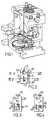
- a known wire-rod block of this kind is shown in Figure 1.
- the drive torque generated by the input shaft 1 is transmitted over a helical bevel gear 2 and a gear wheel 3 which has helical teeth and is mounted on a roll-ring carrying shaft 4, which, in turn, drives a roll-ring carrying shaft 6 synchrnously with the shaft 4, over a gear wheel 5.
- the object of the invention is to improve a wire-rod block of this kind, by reducing the number of rotating parts and by distributing the drive torque of the input shaft more efficiently.
- a wire-rod block of the aforesaid kind in that, in accordance with the invention, the input drive shaft drives one of the roll-ring shafts directly over a first bevel gear and also an output shaft over a gear, said output shaft in turn driving the shaft of the other roll-ring over a second bevel gear, wherein the transmission ratio of the gearing and the bevel gears are such that the roll rings will rotate at mutually the same peripheral speed.
- the inventive wire-rod block thus has a separate bevel gear for transmitting the drive torque to each roll ring.
- the inventive construction Since the properties of the bevel gear of the known construction are dimensioned for the maximum drive torque that can be transmitted to the roll rings, the inventive construction enables a larger torque to be transmitted than said known construction, owing to the fact that the drive torque is distributed between two bevel gears. Furthermore, the inventive construction provides a more compact unit with fewer shaft bearings, because the reduction gear located behind the bevel gear of the known construction is not found in the inventive block.
- the inventive block is also advantageous from the aspect of maintenance, since the block can be easily disengaged from the wire rolling line and removed therefrom entirely, thereby enabling maintenance to be carried out at some other location.
- the wire-rod block includes an input drive shaft 10 which drives an output shaft 12 via a reduction gear 11, said output shaft being intended to form the drive shaft for the nearest wire-rod block in the wire rolling line.
- the shaft 10 also drives a shaft 15 via a bevel gear 13.
- the shaft 15 is perpendicular to the shaft 10 and carries a roll ring 16 on the end thereof remote from its bevel gear.
- the other roll ring,18, of the block is carried by a shaft 17, which is driven by the output shaft, via a bevel gear 14.
- the described components, with the exception of the roll rings 16,18, are enclosed and journalled in a housing 20.
- the roll rings 16,18 of the illustrated embodiment have mutually the same diameter, which means that the shafts 15,17 carrying the roll rings shall be driven for rotation at mutually the same speed, so as the achieve uniform rolling of the wire rod between the roll rings.
- the input shaft 10 is preferably driven at the same speed as that desired of the shaft 15, which thus implies that the bevel gear 13 shall have a transmission ratio of 1:1.
- the reference 19 identifies shaft couplings, which are shown schematically in Figures 2-4.
- the invention provides a wire-rod block of simple construction and with only few components. Compared with prior art wire-rod blocks, the invention provides a compact block with fewer components and therewith fewer bearings.This enables the roll rings to be rotated at higher speeds without risk for an increase in vibration stresses or bearing fractures. Maintenance is also simpler with the inventive block, since the whole unit can be dismantled and taken away from the rolling line,owing to the shaft couplings, whereafter a replacement can be readily fitted. This means that idling times will be shorter than was earlier the case and that maintenance need not be carried out on site.
Landscapes
- Engineering & Computer Science (AREA)
- Mechanical Engineering (AREA)
- Metal Rolling (AREA)
- Gear Transmission (AREA)
- Reduction Rolling/Reduction Stand/Operation Of Reduction Machine (AREA)
- Metal Extraction Processes (AREA)
- Transmission Devices (AREA)
- Rolling Contact Bearings (AREA)
- Structure Of Transmissions (AREA)
- Superconductors And Manufacturing Methods Therefor (AREA)
- Surgical Instruments (AREA)
Priority Applications (1)
| Application Number | Priority Date | Filing Date | Title |
|---|---|---|---|
| AT89850062T ATE72523T1 (de) | 1988-03-11 | 1989-02-22 | Drahtblock. |
Applications Claiming Priority (2)
| Application Number | Priority Date | Filing Date | Title |
|---|---|---|---|
| SE8800880 | 1988-03-11 | ||
| SE8800880A SE460768B (sv) | 1988-03-11 | 1988-03-11 | Traadblock |
Publications (2)
| Publication Number | Publication Date |
|---|---|
| EP0332597A1 EP0332597A1 (en) | 1989-09-13 |
| EP0332597B1 true EP0332597B1 (en) | 1992-02-12 |
Family
ID=20371658
Family Applications (1)
| Application Number | Title | Priority Date | Filing Date |
|---|---|---|---|
| EP89850062A Expired - Lifetime EP0332597B1 (en) | 1988-03-11 | 1989-02-22 | A wire-rod block |
Country Status (9)
| Country | Link |
|---|---|
| US (1) | US4966027A (https=) |
| EP (1) | EP0332597B1 (https=) |
| JP (1) | JP2627659B2 (https=) |
| AT (1) | ATE72523T1 (https=) |
| CA (1) | CA1326607C (https=) |
| DE (1) | DE68900817D1 (https=) |
| ES (1) | ES2029565T3 (https=) |
| GR (1) | GR3003798T3 (https=) |
| SE (1) | SE460768B (https=) |
Families Citing this family (4)
| Publication number | Priority date | Publication date | Assignee | Title |
|---|---|---|---|---|
| EP0479749B1 (en) * | 1990-10-03 | 1995-03-01 | Nippon Steel Corporation | Sizing-rolling method for continuous length sections, rolling mill driving mechanism, roll depressing mechanism and roll fixing mechanism |
| RU2173589C2 (ru) * | 1998-02-03 | 2001-09-20 | Морган Констракшн Компани | Устройство привода клетей прокатного стана с выбираемым соотношением скоростей |
| JP6273039B2 (ja) | 2014-04-03 | 2018-01-31 | ノバルティス アーゲー | コンタクトレンズを消毒および洗浄するための電気化学的システム |
| CN114472529A (zh) * | 2021-12-30 | 2022-05-13 | 重庆钢铁股份有限公司 | 一种双高棒制动器 |
Family Cites Families (11)
| Publication number | Priority date | Publication date | Assignee | Title |
|---|---|---|---|---|
| US749823A (en) * | 1904-01-19 | Universal mill | ||
| US1071720A (en) * | 1912-08-13 | 1913-09-02 | Joseph Fawell | Rolling-mill. |
| US2311075A (en) * | 1940-03-05 | 1943-02-16 | Morgan Construction Co | Rolling mill |
| US3336781A (en) * | 1964-08-24 | 1967-08-22 | Morgan Construction Co | Rolling mill |
| FR1445584A (fr) * | 1965-06-14 | 1966-07-15 | Schwermaschb E Thalmann Veb | Cage de laminoir |
| DE1452155A1 (de) * | 1965-12-06 | 1968-11-28 | Schwermaschb Ernst Thaelmann V | Antrieb eines Vierwalzengeruestes |
| DE2116426B1 (de) * | 1971-04-03 | 1972-10-19 | Bau-Stahlgewebe GmbH, 4000 Düsseldorf-Oberkassel | Walzgerüst zur Kaltbearbeitung von Walzstahl in Stab- oder Drahtform |
| DE2446905A1 (de) * | 1974-10-01 | 1976-04-08 | Moeller & Neumann Gmbh | Drahtwalzwerk in blockform, sog. drahtblock |
| US4024746A (en) * | 1975-01-28 | 1977-05-24 | Demag Aktiengesellschaft | Stand gearing arrangement for the rolls of a continuous rolling mill |
| JPS53123743A (en) * | 1977-04-05 | 1978-10-28 | Koyo Seiko Co Ltd | Detachable device for drive mechanism |
| DD158312A3 (de) * | 1980-12-11 | 1983-01-12 | Peter Kletzin | Innen-und aussenverzahnung zum antrieb eines spindellosen walzgeruestes |
-
1988
- 1988-03-11 SE SE8800880A patent/SE460768B/sv not_active IP Right Cessation
-
1989
- 1989-02-22 ES ES198989850062T patent/ES2029565T3/es not_active Expired - Lifetime
- 1989-02-22 DE DE8989850062T patent/DE68900817D1/de not_active Expired - Fee Related
- 1989-02-22 AT AT89850062T patent/ATE72523T1/de not_active IP Right Cessation
- 1989-02-22 EP EP89850062A patent/EP0332597B1/en not_active Expired - Lifetime
- 1989-02-27 US US07/315,573 patent/US4966027A/en not_active Expired - Lifetime
- 1989-03-03 CA CA000592683A patent/CA1326607C/en not_active Expired - Fee Related
- 1989-03-09 JP JP1057658A patent/JP2627659B2/ja not_active Expired - Lifetime
-
1992
- 1992-02-13 GR GR910402021T patent/GR3003798T3/el unknown
Also Published As
| Publication number | Publication date |
|---|---|
| DE68900817D1 (de) | 1992-03-26 |
| US4966027A (en) | 1990-10-30 |
| CA1326607C (en) | 1994-02-01 |
| ATE72523T1 (de) | 1992-02-15 |
| SE8800880L (sv) | 1989-09-12 |
| JPH01284416A (ja) | 1989-11-15 |
| SE460768B (sv) | 1989-11-20 |
| GR3003798T3 (https=) | 1993-03-16 |
| SE8800880D0 (sv) | 1988-03-11 |
| JP2627659B2 (ja) | 1997-07-09 |
| EP0332597A1 (en) | 1989-09-13 |
| ES2029565T3 (es) | 1992-08-16 |
Similar Documents
| Publication | Publication Date | Title |
|---|---|---|
| US4317389A (en) | Vehicle drive transmission system | |
| CA2091747A1 (en) | Power Transmission for Mechanical Press | |
| US4807458A (en) | Dividing gear unit for a roll block | |
| EP0332597B1 (en) | A wire-rod block | |
| US5921152A (en) | Optional multi-ratio gear transmission system | |
| EP0503592B1 (en) | Gearbox with hydrostatic motors particularly for earth-movers | |
| US4286481A (en) | Power transfer device | |
| EP0189518B1 (de) | Zahnradgetriebe | |
| EP0728962A3 (de) | Hydrostatisch-mechanisches Leistungsverzweigungsgetriebe | |
| US4385530A (en) | Transmission for driving a stretch-reducing rolling mill | |
| US4848185A (en) | Transmission for driving the rolls of a rolling line | |
| NZ299180A (en) | Reduction gear arrangement; comprises a driving pinion, two intermediate idler pinions and a driven gear wheel | |
| US4370849A (en) | Stranding device of a stranding machine | |
| DE3045080A1 (de) | Stufenloser drehmomentwandler | |
| GB2298259A (en) | A mechanical transmission having an angled intermediate shaft | |
| SU1132092A1 (ru) | Замкнута зубчата передача | |
| SU1601433A1 (ru) | Редуктор | |
| JPS6181294A (ja) | 自動定速pto装置 | |
| SU1586820A1 (ru) | Устройство дл непрерывной намотки проволоки | |
| SU1232323A1 (ru) | Устройство дл правки листовых заготовок | |
| MXPA99001141A (en) | Multiple relief gear transmission system option | |
| CA2205494A1 (en) | Power transmission for mechanical press | |
| CA2113853A1 (en) | Gearcase for transmitting motion with different speeds to at least two driving shafts for power devices in self-propelled farm machines | |
| JPS57160778A (en) | Foot drive unit for walking machine | |
| RU99102532A (ru) | Устройство привода клетей прокатного стана с выбираемым соотношением скоростей |
Legal Events
| Date | Code | Title | Description |
|---|---|---|---|
| PUAI | Public reference made under article 153(3) epc to a published international application that has entered the european phase |
Free format text: ORIGINAL CODE: 0009012 |
|
| AK | Designated contracting states |
Kind code of ref document: A1 Designated state(s): AT BE CH DE ES FR GB GR IT LI LU NL SE |
|
| 17P | Request for examination filed |
Effective date: 19900307 |
|
| 17Q | First examination report despatched |
Effective date: 19910425 |
|
| GRAA | (expected) grant |
Free format text: ORIGINAL CODE: 0009210 |
|
| ITF | It: translation for a ep patent filed | ||
| AK | Designated contracting states |
Kind code of ref document: B1 Designated state(s): AT BE CH DE ES FR GB GR IT LI LU NL SE |
|
| REF | Corresponds to: |
Ref document number: 72523 Country of ref document: AT Date of ref document: 19920215 Kind code of ref document: T |
|
| REF | Corresponds to: |
Ref document number: 68900817 Country of ref document: DE Date of ref document: 19920326 |
|
| ET | Fr: translation filed | ||
| REG | Reference to a national code |
Ref country code: ES Ref legal event code: FG2A Ref document number: 2029565 Country of ref document: ES Kind code of ref document: T3 |
|
| REG | Reference to a national code |
Ref country code: GR Ref legal event code: FG4A Free format text: 3003798 |
|
| PLBE | No opposition filed within time limit |
Free format text: ORIGINAL CODE: 0009261 |
|
| STAA | Information on the status of an ep patent application or granted ep patent |
Free format text: STATUS: NO OPPOSITION FILED WITHIN TIME LIMIT |
|
| 26N | No opposition filed | ||
| EPTA | Lu: last paid annual fee | ||
| EAL | Se: european patent in force in sweden |
Ref document number: 89850062.4 |
|
| PGFP | Annual fee paid to national office [announced via postgrant information from national office to epo] |
Ref country code: SE Payment date: 19971127 Year of fee payment: 10 |
|
| PGFP | Annual fee paid to national office [announced via postgrant information from national office to epo] |
Ref country code: GR Payment date: 19971230 Year of fee payment: 10 Ref country code: FR Payment date: 19971230 Year of fee payment: 10 |
|
| PGFP | Annual fee paid to national office [announced via postgrant information from national office to epo] |
Ref country code: LU Payment date: 19980115 Year of fee payment: 10 Ref country code: BE Payment date: 19980115 Year of fee payment: 10 |
|
| PGFP | Annual fee paid to national office [announced via postgrant information from national office to epo] |
Ref country code: NL Payment date: 19980121 Year of fee payment: 10 |
|
| PGFP | Annual fee paid to national office [announced via postgrant information from national office to epo] |
Ref country code: ES Payment date: 19980210 Year of fee payment: 10 Ref country code: AT Payment date: 19980210 Year of fee payment: 10 |
|
| PGFP | Annual fee paid to national office [announced via postgrant information from national office to epo] |
Ref country code: GB Payment date: 19980217 Year of fee payment: 10 |
|
| PGFP | Annual fee paid to national office [announced via postgrant information from national office to epo] |
Ref country code: DE Payment date: 19980324 Year of fee payment: 10 |
|
| PGFP | Annual fee paid to national office [announced via postgrant information from national office to epo] |
Ref country code: CH Payment date: 19980511 Year of fee payment: 10 |
|
| PG25 | Lapsed in a contracting state [announced via postgrant information from national office to epo] |
Ref country code: LU Free format text: LAPSE BECAUSE OF NON-PAYMENT OF DUE FEES Effective date: 19990222 Ref country code: GB Free format text: LAPSE BECAUSE OF NON-PAYMENT OF DUE FEES Effective date: 19990222 Ref country code: AT Free format text: LAPSE BECAUSE OF NON-PAYMENT OF DUE FEES Effective date: 19990222 |
|
| PG25 | Lapsed in a contracting state [announced via postgrant information from national office to epo] |
Ref country code: SE Free format text: LAPSE BECAUSE OF NON-PAYMENT OF DUE FEES Effective date: 19990223 Ref country code: ES Free format text: LAPSE BECAUSE OF EXPIRATION OF PROTECTION Effective date: 19990223 |
|
| PG25 | Lapsed in a contracting state [announced via postgrant information from national office to epo] |
Ref country code: LI Free format text: LAPSE BECAUSE OF NON-PAYMENT OF DUE FEES Effective date: 19990228 Ref country code: GR Free format text: LAPSE BECAUSE OF NON-PAYMENT OF DUE FEES Effective date: 19990228 Ref country code: CH Free format text: LAPSE BECAUSE OF NON-PAYMENT OF DUE FEES Effective date: 19990228 Ref country code: BE Free format text: LAPSE BECAUSE OF NON-PAYMENT OF DUE FEES Effective date: 19990228 |
|
| BERE | Be: lapsed |
Owner name: MORGARDSHAMMAR A.B. Effective date: 19990228 |
|
| PG25 | Lapsed in a contracting state [announced via postgrant information from national office to epo] |
Ref country code: NL Free format text: LAPSE BECAUSE OF NON-PAYMENT OF DUE FEES Effective date: 19990901 |
|
| GBPC | Gb: european patent ceased through non-payment of renewal fee |
Effective date: 19990222 |
|
| REG | Reference to a national code |
Ref country code: CH Ref legal event code: PL |
|
| PG25 | Lapsed in a contracting state [announced via postgrant information from national office to epo] |
Ref country code: FR Free format text: LAPSE BECAUSE OF NON-PAYMENT OF DUE FEES Effective date: 19991029 |
|
| EUG | Se: european patent has lapsed |
Ref document number: 89850062.4 |
|
| PG25 | Lapsed in a contracting state [announced via postgrant information from national office to epo] |
Ref country code: DE Free format text: LAPSE BECAUSE OF NON-PAYMENT OF DUE FEES Effective date: 19991201 |
|
| REG | Reference to a national code |
Ref country code: FR Ref legal event code: ST |
|
| REG | Reference to a national code |
Ref country code: ES Ref legal event code: FD2A Effective date: 20010601 |
|
| PG25 | Lapsed in a contracting state [announced via postgrant information from national office to epo] |
Ref country code: IT Free format text: LAPSE BECAUSE OF NON-PAYMENT OF DUE FEES Effective date: 20050222 |