EP0332520B1 - Aufnahmegerät mit drehendem Kopf und mit einer drehbaren elektrischen Kopplungsvorrichtung - Google Patents
Aufnahmegerät mit drehendem Kopf und mit einer drehbaren elektrischen Kopplungsvorrichtung Download PDFInfo
- Publication number
- EP0332520B1 EP0332520B1 EP89400616A EP89400616A EP0332520B1 EP 0332520 B1 EP0332520 B1 EP 0332520B1 EP 89400616 A EP89400616 A EP 89400616A EP 89400616 A EP89400616 A EP 89400616A EP 0332520 B1 EP0332520 B1 EP 0332520B1
- Authority
- EP
- European Patent Office
- Prior art keywords
- recorder
- reader
- capacitor
- magnetic tape
- tape according
- Prior art date
- Legal status (The legal status is an assumption and is not a legal conclusion. Google has not performed a legal analysis and makes no representation as to the accuracy of the status listed.)
- Expired - Lifetime
Links
Images



Classifications
-
- G—PHYSICS
- G11—INFORMATION STORAGE
- G11B—INFORMATION STORAGE BASED ON RELATIVE MOVEMENT BETWEEN RECORD CARRIER AND TRANSDUCER
- G11B5/00—Recording by magnetisation or demagnetisation of a record carrier; Reproducing by magnetic means; Record carriers therefor
- G11B5/48—Disposition or mounting of heads or head supports relative to record carriers ; arrangements of heads, e.g. for scanning the record carrier to increase the relative speed
- G11B5/52—Disposition or mounting of heads or head supports relative to record carriers ; arrangements of heads, e.g. for scanning the record carrier to increase the relative speed with simultaneous movement of head and record carrier, e.g. rotation of head
- G11B5/53—Disposition or mounting of heads on rotating support
-
- G—PHYSICS
- G11—INFORMATION STORAGE
- G11B—INFORMATION STORAGE BASED ON RELATIVE MOVEMENT BETWEEN RECORD CARRIER AND TRANSDUCER
- G11B5/00—Recording by magnetisation or demagnetisation of a record carrier; Reproducing by magnetic means; Record carriers therefor
- G11B5/48—Disposition or mounting of heads or head supports relative to record carriers ; arrangements of heads, e.g. for scanning the record carrier to increase the relative speed
- G11B5/52—Disposition or mounting of heads or head supports relative to record carriers ; arrangements of heads, e.g. for scanning the record carrier to increase the relative speed with simultaneous movement of head and record carrier, e.g. rotation of head
- G11B5/53—Disposition or mounting of heads on rotating support
- G11B5/531—Disposition of more than one recording or reproducing head on support rotating cyclically around an axis
Definitions
- the present invention relates to a rotating head recorder, provided with a rotary electrical coupling device.
- Such recorders comprise one or more magnetic recording / reading heads, fixed on the periphery of an element of revolution, coaxial with the axis of a cylindrical drum against the surface of which is helically wound a magnetic strip moving between a transmitting coil and a receiving coil.
- the information is recorded on the tape according to oblique tracks whose inclination is a function of the ratio of the respective speeds of the tape and the head.
- Recorders of this type include two families. In the first family, the heads are fixed on the periphery of a turntable, coaxial with the drum, and arranged in a slot provided in an equatorial plane of the drum; in front of the slot scrolls said magnetic strip wound helically on the drum. In the other family, the drum comprises a fixed lower part and a rotating upper part at the base of which the heads are fixed.
- a device is provided for each head. rotary electrical coupling between the fixed part and the rotating parts (head support plate) of the recorder.
- the coupling device consists, for each head, of a rotary transformer comprising a rotor (associated with the head support plate) and a stator (fixed), both cylindrical or annular; the rotor and the stator are each provided, in their face opposite a groove in which is disposed a winding of conductive wire, constituting respectively the primary (stator) and the secondary (rotor).
- a rotary transformer comprising a rotor (associated with the head support plate) and a stator (fixed), both cylindrical or annular; the rotor and the stator are each provided, in their face opposite a groove in which is disposed a winding of conductive wire, constituting respectively the primary (stator) and the secondary (rotor).
- recorders of this type must be able to record and read data at data flow rates which can vary in a high ratio (up to 25 for example), while the format and the inclination of the tracks on the tape is fixed (imposed by a standard, for example). Different rates imply different head-band relative speeds which must therefore also vary within a wide range.
- the resonance phenomena of the equivalent circuit constituted by the leakage impedance and the head impedance in parallel on the different parasitic capacitances affect the upper limit of the frequency band.
- the circuit consisting of the output resistance of the amplifier connected to the transformer and of the transformer inductance has (taking into account the value of the latter) a low cut-off frequency affecting the lower limit of the frequency band.
- the frequency range obtained by known transformers is at best of the order of 100 KHz to 30 (or 40) MHz. This range is not wide enough to meet the needs, taking into account the possible range of speeds for which a frequency range of 3 KHz - 200 MHz (at - 3 dB) would be necessary.
- the transfer impedance of the transformer is difficult to control, over the required frequency range, in particular because of the ferrite used to make the transformer and whose characteristics are difficult to control.
- the relative head / tape speed is fixed and the recorder comprises a buffer memory containing a quantity of data which varies with time and which is linked to fluctuations in the value of the information flow.
- a second known solution consists in placing an electronic amplification circuit on the head support plate, for each head; each circuit is arranged between the head and the rotary transformer associated with the latter. Respective recording / playback signals of coherent levels are obtained, since it is thus possible to reduce the level necessary for recording and to increase the level of the signals at playback; the consistency of the levels results in a reduction in crosstalk.
- the bandwidth obtained is increased; in fact, the magnetic head is separated from the imperfect coupler constituted by the rotary transformer; it is therefore possible to give the intrinsic inductance of the transformer a value such as the impedance ratio clean on transformer leakage impedance is increased; in any event, this relationship has a less decisive influence (by the presence of the amplification circuit on the stage) than in the other known solutions (without amplification circuit on the stage).
- the present invention overcomes these drawbacks, and proposes a coupling device which is simple to produce, which allows a wide frequency band, and overcomes the differences in signal levels between recording and playback.
- the magnetic tape recorder / player comprising at least one magnetic head driven by a rotational movement at the periphery of an equatorial slot of a cylindrical drum on the surface of which the tape is wound helically and a rotary electrical coupling device, said device being intended to transmit electrical signals representative of information recorded / read on the tape, between a rotary part linked to the rotor head and a fixed part forming a stator linked to electronic means respectively for transmitting and / or receiving this information, is characterized in that it comprises, for each head, a capacitor comprising only two concentric conductive armatures and of cylindrical shape arranged one opposite the other and respectively secured one to the rotor, the other to the stator.
- each frame is integral with a body forming a support of generally annular shape, made of insulating material.
- the frames are arranged on the support body by metallization.
- each body has a generally U-shaped section, the bases of which are coplanar and transverse to the rotor, the conductive armatures being attached to the respective external faces of the branches opposite said body.
- the height of the armatures is less than the height of each body, so as to provide on either side of the armature a free strip of the body, thereby increasing the distance separating the armature from the metal parts arranged nearby.
- two metal shielding rings of generally L-shaped section, one branch of which is arranged transversely to the rotor and attached to the base of the respectively rotating and fixed parts of the capacitor.
- shielding rings each provided with a return plated against the face of each body carrying the corresponding reinforcement.
- the receiving armature of each capacitor is connected to a receiving circuit comprising a high input impedance element, such as a field effect transistor.
- the receiver circuit further comprises an impedance of high value compared to the sum of the capacitance of the coupling capacitor and the input capacity of the receiver circuit.
- this high impedance is made up of several impedances arranged in an arrangement of the so-called "boot-strap" type.
- the receiving circuit is arranged near the receiving armature.
- the device according to the invention is capable of being applied to a recorder / reader comprising two series of magnetic heads, one for recording, the other for reading.
- the capacitors of coupling are also separated into two groups, one for recording, the other for playback.
- the emitting armature is the fixed armature while the receiving armature is the rotating armature.
- the correspondence is inverse for a coupling capacitor for reading.
- the receiving circuit is arranged on the part of the capacitor linked to the hub secured to the carrier plate. heads and forming rotor, and preferably on the upper face of the annular body forming the rotating part of the capacitor.
- the emitting armature is connected to an emitting circuit, comprising a transistor with low output impedance.
- the device comprises mass return means, operating in differential mode and provided with additional rotary coupling means, associated with means capable of delivering, at the terminals of said additional coupling means, a current in the opposite direction to that passing through. each of the coupling capacitors transmitting the information signals.
- the ground return means comprise an additional capacitor, an armature of which is connected to the output of a first amplifier, the input of which is connected to the output of a first summing / inverter circuit receiving the currents relating to each of the signals respectively from the transmitter circuits (specific to recording capacitors); the other armature of said additional capacitor is connected to the output of a second amplifier, the input of which is connected to the output of a second summing / reversing circuit receiving the currents relating to each of the signals originating respectively from the receiving circuits (specific to read capacitors).
- a summing / reversing circuit is understood to mean a circuit delivering an output signal corresponding to the sum of the input signals assigned the minus sign.
- the invention also relates to a recorder / player with a rotating head provided with a coupling device of the type described in the present application.
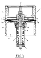
- the device of the present invention is described below in relation to an example of application in the field of recording / reading apparatuses with rotating magnetic heads, of the type known per se and as shown diagrammatically in FIGS. 1 and 2.
- the recorder / player comprises a cylindrical drum 1 which breaks down into upper drum 2 and lower drum 3, separated by a slot 4 arranged in an equatorial plane perpendicular to the axis I-I of the drum and substantially halfway up the latter.
- a disc-shaped element 5 is provided, capable of being driven in a rotary movement around the axis I-I of the drum.
- the disc carries one, and generally several, magnetic heads 6 arranged regularly on its periphery and projecting very slightly from the surface defining the wall of the drum.
- a magnetic strip 7 is capable of being wound helically around the drum 1 to form, in top view as shown in FIG. 2, an omega.
- a set of rollers 8 to 11 guide the strip 7 and maintain it according to this configuration during its travel, from a supply reel to a take-up reel (not shown and known per se). The information is recorded / read from the tape along segments of tracks parallel and oblique to the axis of the tape.
- the invention also applies to recorders / players of the type in which the heads are fixed on the periphery of the base of a rotating upper drum, coaxial with a fixed lower drum, the strip running in front of the slot defined between the two drums.
- the disc or plate 5 comprises on its periphery radial tongues 12, 13 at the end of each of which is fixed a magnetic head 6A, 6B.
- the disc is integral with a hub 14 coaxial with the axis I-I of the drum 1 and mounted for rotation on the stator 15; said hub 14 (forming rotor) is linked to the drum by means of ball bearings (known per se) respectively upper 16 and lower 17.
- This jacket of diameter greater than that of the hub, defines a cylindrical chamber 19 where members are housed rotary electrical coupling (objects of the invention), intended to ensure the connection between the magnetic heads linked to the rotor and the electronic means (not shown in FIGS. 1 and 2), respectively transmitters and receivers of information, and linked to the stator .
- the magnetic recorder / reader can be placed on board an aircraft and receives the information coming from sensors and / or control and / or command members of said aircraft. This information is thus stored on magnetic tape to be generally read and used later.
- said transmitting means send information to be recorded on tape to the heads, via the coupling members (described below); during reading, the information is conveyed in the other direction, from the heads to the electronic means able to store said information and / or send it to operating means.
- the rotary electrical coupling members consist of capacitive members, described below in conjunction with FIGS. 4 to 9.
- Figure 4 is shown schematically the path of information flow within a magnetic recorder / reader to which the invention applies.
- a rotary disc 5 On the periphery of a rotary disc 5 are arranged eight magnetic heads 20 to 27 regularly spaced.
- the recorder / player comprises eight heads, four of which (20, 22, 24 and 26) are intended for recording and four others (21, 23, 25 and 27) are intended for reading. .
- Means 28 transmitters of information connected to the sources of information to be recorded, have their output connected to rotating electrical coupling members, (in number equal to the number of recording heads), carrying the respective references 29, 30, 31 and 32, and ensuring the electrical coupling between the fixed parts (stator) and the rotating parts (rotor); only the axis of the rotor is shown in Figure 4.
- the rotating part of each rotating electrical coupling member 29, 30, 31 and 32 is connected to the recording heads 20, 22, 24 and 26, via an electronic circuit d amplification respectively 33, 34, 35 and 36, arranged on the disc 5.
- each read head 21, 23, 25 and 27 is connected via amplification circuits 38, 39, 40 and 41 respectively disposed on the disc 5, to the rotating part of coupling members. electrical respectively 42, 43, 44 and 45; the fixed part of the latter is connected to the input of means 46 for receiving the read information which is then routed either to storage or operating means (not shown). Said respectively receiving and storage means are known in themselves.
- each magnetic head corresponds to a capacitive coupling member.
- Said coupling members are coaxial and arranged close to each other, along the axis of the rotor.
- eight coupling members are provided, namely four for recording and four for reading.
- Means are also provided for supplying electrical energy 47, comprising an energy source 48 and rotating members 49 (known per se) intended to ensure the transmission of energy between the stator and the rotor.
- FIG. 5 shows in perspective a recording coupling member 29 and a reading coupling member 42.
- Each coupling member constitutes a rotating capacitor formed by two concentric cylindrical armatures, of conductive material and arranged at the same height relative to the axis of the rotor; a first armature 50 is linked to the rotor, and therefore rotating, while the second 51, of slightly larger diameter, is integral with the stator, therefore fixed.
- the radial distance between the external wall of the rotating armature 50 and the internal wall of the fixed armature 51 is, for example, of the order of 35 to 60 microns, for a reinforcement diameter of the order of 15 at 25 mm.
- the transfer capacity is of the order of a few pF to a few tens of pF, typically from 10 to 30 pF.
- the dielectric material between armatures of the same capacitor is ambient air.
- Each coupling capacitor comprises a transmission armature and a reception armature.
- the emission armature is the fixed frame
- the receiving frame is the rotating frame.
- the correspondence is inverse for a read capacitor.
- An emitter circuit 52 (part of the emitter means 28) is connected by its output to the fixed armature 51 of the coupling capacitor 29 for recording, while the rotating armature 50 is connected to the input of a receiver circuit 53, the output of which is connected (via the rotor) to the magnetic head 22 via the corresponding amplification circuit 34 (cf. FIG. 4).
- a receiver circuit 53 the output of which is connected (via the rotor) to the magnetic head 22 via the corresponding amplification circuit 34 (cf. FIG. 4).
- the rotating armature 50 bis, of the coupling capacitor 42 for reading is linked directly to the head 21 via the amplification circuit 38, while the fixed armature 51 bis is connected to the input of a receiver circuit 54 forming part of the receiver means (cf. FIG. 4).
- the coupling capacitors are produced in the manner described below, in connection with FIG. 6A showing an advantageous example of embodiment of two successive coupling capacitors 29 and 30. It is understood that in practice, eight similar capacitors are thus arranged along the rotor (according to the example in FIG. 4).
- Each metal frame 50, 51 of the capacitor 29 is mounted on a body 55 and 56 respectively of insulating material, in the form of a ring, the cross section of which is U-shaped.
- the first body 55 is integral with its smaller part diameter, of the hub 14 of the rotor, while its part of larger diameter (constituting the other branch of the U seen in section) carries on its external face the rotating frame 50.
- the second body 56 (fixed) has a shape identical to that of the first body 55 (rotating), but is larger diameter; its part of smaller diameter (forming a branch of the U) carries on its external face the fixed frame 51 (opposite the rotating frame 50), while its part of larger diameter (the other branch of the U) is integral with the stator.
- the bodies 55, 56 are respectively linked to the stator and to the rotor by glue, for example.
- the height of the reinforcements is less than the height of the side of the corresponding body on which they are fixed.
- shielding rings are provided in the general shape of L; thus, a first ring 57 is attached to the underside (base of the U) of the first body, while a second ring 58 is fixed to the base of the second body 56.
- the shielding rings 57 and 58 respectively comprise a branch 57A, 58A placed on the base of the U of each body 55, 56, a branch 57B, 58B (perpendicular) pressed against the external face of the branch of the U opposite to that where the corresponding reinforcement is fixed (50,51).
- Each ring includes a return to one of its ends, namely that close to the corresponding reinforcement; returns 57C and 58C are plated on the lower part of the face of the body carrying the reinforcements.
- This embodiment of the capacitors is advantageous because it reduces the stray capacitances; in fact, two respective armatures, rotating or fixed, of two neighboring capacitors (offset along the axis of the rotor) have a very small opposite surface, substantially of the order of their thickness (namely a few microns).
- FIG. 7 represents a detailed view, extracted from schematic figure 4, of the whole of the electronic circuitry, associated with one of the magnetic read heads.
- the read head 21 is connected to its associated amplification circuit 38, both arranged on the turntable 5.
- the output of the circuit 38 (known per se) is connected, by the hub 14 of the rotor, to the coupling capacitor 42 and more precisely to the rotating armature 50 bis, which here constitutes the receiving armature.
- the fixed frame 51 bis which here constitutes the emitting frame, is connected to the reading means 46 (FIG. 4).
- the dotted dividing lines respectively a-a and b-b indicate the respective location of the above mentioned elements.
- the information after having been picked up by the head 21, is amplified by the circuit 38, then transmitted from the rotor to the stator by the coupling capacitor 42, then to the means 46 for reading and processing, via the receiver circuit 54 high impedance .
- Amplification circuit 38 has a low output impedance, for example 10 ohms.
- the receiver circuit 54 includes a high input impedance element, namely a field effect transistor TEC1, the gate of which receives the signal from the armature 51 bis and is also connected to mass return means M via the impedances Z2 and Z3 connected in series; the TEC1 drain is connected to a positive voltage source V +; the source of TEC1 is linked on the one hand to a negative voltage source V- by an impedance Z4, and on the other hand to the mass return means M, via the impedance Z3.
- a high input impedance element namely a field effect transistor TEC1
- the TEC1 drain is connected to a positive voltage source V +
- the source of TEC1 is linked on the one hand to a negative voltage source V- by an impedance Z4, and on the other hand to the mass return means M, via the impedance Z3.
- mass return means M means means making it possible to ensure the return of the electrical ground from the rotating circuits to the stator.
- the impedances Z2 and Z3 are resistors (0.5 Mohms) and the impedance Z4 a capacitor (whose capacity is worth a few nF).
- Figure 8 shows in detail the whole circuitry electronic for one of the recording heads, in this case the head 20.
- the emitter means 28 (cf. FIG. 4) have a low output impedance and are connected to the coupling capacitor 29, more precisely to the fixed armature 51.
- the rotating armature 50 is connected to the receiver circuit 53 (cf. FIGS. 4 and 5) linked to the rotor; the output of circuit 53 is connected to amplification circuit 33 associated with the recording head 20, both mounted on the plate.
- the receiver circuit 53 is similar, in its design and operation, to the receiver circuit 54 of FIG. 7; the same applies to the amplifier circuit 33, similar to the amplifier circuit 38 of FIG. 7.
- the receiving circuits are arranged as close as possible to the corresponding receiving armature of the associated coupling capacitor.
- a line too long to transmit the signal from the capacitor to the receiving circuit would be subject to the influence of the parasitic capacitances on the one hand (resulting in a strong attenuation) and on the other hand of the parasitic on the line taking into account the high value of l input impedance of the receiving circuit with respect to the line impedance.
- the receiver circuits 53a, 53b, 53c, 53d associated with the recording capacitors, and therefore arranged on the rotating part are arranged on the support body of the frames, and more precisely on the upper face of the U-shaped base (view in section; see Figure 6).
- the receiving circuits (rotating 53a, 53b, 53c, 53d) and the amplifier circuits arranged on the stage are produced according to the surface mounting technique.
- the transmitting circuits 52a, 52b, 52c and 52d of the information transmit it via the respective coupling capacitors 29, 30, 31 and 32, and the respective receiving circuits 53a, 53b, 53c, and 53d, towards the heads d 'recording 20, 22, 24 and 26.
- the read heads 21, 23, 25 and 27 pick up the information on the tape; these are transmitted via the respective amplifier circuits 38 to 41, and via the coupling capacitors 42 to 45 to the receiver circuits 54a, 54b, 54c and 54d, then to the reading means 46.
- the device comprises mass return means described below with reference to Figure 9 where elements similar to those of Figure 4 have the same references.
- circuits described above include ground connections, which requires a ground return common to the circuits arranged on the rotary members (plate and rotor).
- the summing circuits 60 and 61 deliver the sum of the input signals assigned the minus sign; for example, the summator / inverter 60 receives four current values i1, i2, i3 and i4, and delivers a current output signal - (i1 + i2 + i3 + i4).
- the additional coupling capacitor 64 receives on its fixed armature the inverted sum of the recording currents coming from the emitter circuits, while its rotating armature receives the inverted sum of reading currents from the amplifiers 38-41 (arranged on the tray).
- the additional coupling capacitor achieves a mode which could be called pseudo differential mode.
- a rotating ground contact of the mechanical type which receives all the masses shown on the circuits of the figures.
- the purpose of this mechanical rotating contact is to avoid the accumulation of static electrical charges of high potential on the rotating parts of the recorder (rotor, plate).
- This second variant makes it possible, like the embodiment shown in FIG. 9 and described above, to ensure that the sum of the currents "passing through" the coupling capacitors is zero.
Landscapes
- Recording Or Reproducing By Magnetic Means (AREA)
- Arrangements For Transmission Of Measured Signals (AREA)
Claims (17)
- Magnetisches Bandaufzeichnungs-/Bandlesegerät, mit wenigstens einem Magnetkopf (20-27), der zu einer Drehbewegung längs des Umfangs eines äquatorialen Schlitzes (4) einer zylindrischen Trommel (1) angetrieben wird, auf deren Oberfläche sich ein schraubenlinienförmig gewundenes Band (7) vorbeibewegt, und einer Vorrichtung zur elektrischen Drehkopplung, die dazu bestimmt ist, elektrische Signale, die auf das Band (7) aufgezeichnete und/oder vom Band (7) gelesene Information darstellen, zwischen einem rotierenden Teil (29-32), der mit dem den Rotor bildenden Kopf verbunden ist, und einem den Stator bildenden festen Teil (42-45), der mit elektronischen Mitteln zum Senden (28) und/oder zum Empfangen (46) dieser Informationen verbunden ist, zu übertragen, dadurch gekennzeichnet, daß es für jeden Kopf (20-27) einen Kondensator (29) enthält, der nur zwei zylindrische und konzentrische leitende Belegungen (50, 51) enthält, die einander gegenüber angeordnet und mit dem Rotor bzw. dem Stator verbunden sind.
- Magnetisches Bandaufzeichnungs-/Bandlesegerät nach Anspruch 1, dadurch gekennzeichnet, daß jede Belegung (50, 51) mit einem Körper (55, 56) aus Isoliermaterial verbunden ist, der einen Träger mit im allgemeinen ringförmiger Form bildet.
- Magnetisches Bandaufzeichnungs-/Bandlesegerät nach Anspruch 2, dadurch gekennzeichnet, daß die Belegungen (50, 51) auf dem Trägerkörper (55, 56) durch Metallisierung aufgebracht sind.
- Magnetisches Bandaufzeichnungs-/Bandlesegerät nach Anspruch 2, dadurch gekennzeichnet, daß die Körper (55, 56) einen Abschnitt mit allgemeiner Form eines U's aufweisen, dessen Grundflächen (57, 58) zum Rotor koplanar und transversal sind, wobei die leitenden Belegungen (50, 51) an die jeweiligen Außenflächen gegenüber den Körpern (55, 56) angefügt sind.
- Magnetisches Bandaufzeichnungs-/Bandlesegerät nach Anspruch 2 oder 3, dadurch gekennzeichnet, daß die Höhe der Belegungen (50, 51) kleiner als die Höhe der Körper (55, 56) ist.
- Magnetisches Bandaufzeichnungs-/Bandlesegerät nach einem der vorangehenden Ansprüche, dadurch gekennzeichnet, daB eine der Belegungen jedes Kondensators mit einer Empfängerschaltung (54) verbunden ist, die ein Element mit groBer Eingangsimpedanz wie etwa einen Feldeffekttransistor (TEC1) enthält.
- Magnetisches Bandaufzeichnungs-/Bandlesegerät nach Anspruch 6, dadurch gekennzeichnet, daB die Empfängerschaltung (54) außerdem eine Impedanz besitzt, deren Wert im Vergleich zur äquivalenten Eingangskapazität des Feldeffekttransistors (TEC1) bei niedriger Frequenz hoch ist.
- Magnetisches Bandaufzeichnungs-/Bandlesegerät nach Anspruch 7, dadurch gekennzeichnet, daB die Impedanz mit hohem Wert durch mehrere Impedanzen (82, 83, 84) gebildet ist, die aus mehreren resistiven und kapazitiven Elementen zusammengesetzt sind und in einer Ersatzschaltung des sogenannten "boot-strap"-Typs angeordnet sind.
- Magnetisches Bandaufzeichnungs-/Bandlesegerät nach einem der vorangehenden Ansprüche, mit einer Serie von magnetischen Köpfen (20, 22, 24, 26) zum Aufzeichnen und einer Serie von magnetischen Köpfen (21, 23, 25, 27) zum Lesen, dadurch gekennzeichnet, daß jedem Kopf ein Kondensator mit Aufzeichnungskopplung (29, 30, 31, 32) bzw. Lesekopplung (42, 43, 44, 45) entspricht.
- Magnetisches Bandaufzeichnungs-/Bandlesegerät nach Anspruch 9, dadurch gekennzeichnet, daß bestimmte der beweglichen Belegungen (50) mit am Rotor angebrachten Schaltungen (53) verbunden sind und daß bestimmte der beweglichen Belegungen (50bis) mit an der Kopfträgerplatte angebrachten Schaltungen (38) verbunden sind.
- Magnetisches Bandaufzeichnungs-/Bandlesegerät nach den Ansprüchen 2, 6 und 10, dadurch gekennzeichnet, daß die am Rotor angebrachte Schaltung (53) eine Empfängerschaltung ist, die an der oberen Fläche des den drehenden Teil des Kondensators (29) tragenden ringförmigen Körpers (55) angebracht ist.
- Magnetisches Bandaufzeichnungs-/Bandlesegerät nach Anspruch 9, dadurch gekennzeichnet, daß es für jeden Kopplungskondensator mit zwei metallischen Abschirmungsringen (57, 58) versehen ist, deren Querschnitt die allgemeine Form eines L's besitzt und wovon die einzelnen Grundflächen transversal zum Rotor angeordnet und an die Grundflächen des drehenden Teils bzw. des festen Teils des Kondensators angefügt sind.
- Magnetisches Bandaufzeichnungs-/Bandlesegerät nach den Ansprüchen 2 und 12, dadurch gekennzeichnet, daß die Abschirmungsringe (57, 58) jeweils mit einem Rücksprung versehen sind, der an die Fläche eines jeden die entsprechende Belegung (50, 51) tragenden Körpers (55, 56) angefügt ist.
- Magnetisches Bandaufzeichnungs-/Bandlesegerät nach einem der vorangehenden Anspriiche, dadurch gekennzeichnet, daß die Sendebelegung mit einer Sendeschaltung verbunden ist, die ein Element mit schwacher Ausgangsimpedanz wie etwa einen Transistor enthält.
- Magnetisches Bandaufzeichnungs-/Bandlesegerät nach den Ansprüchen 6 und 10, dadurch gekennzeichnet, daß die mit den jeweiligen beweglichen Belegungen verbundenen Empfängerschaltungen (53a, 53b, 53c, 53d) sowie die auf der Platte (5) angeordneten Verstärkerschaltungen (38, 39, 40, 41) mittels der Oberflächenmontagetechnik verwirklicht sind.
- Magnetisches Bandaufzeichnungs-/Bandlesegerät nach einem der vorangehenden Ansprüche, dadurch gekennzeichnet, daß es Mittel zur Masserückleitung des drehenden Teils aufweist, die zusätzliche drehende Kopplungsmittel (64) sowie Mittel enthält, die an die Anschlüsse der zusätzlichen Kopplungsmittel einen Strom liefern, der zu demjenigen entgegengesetzt ist, der durch die einzelnen Kopplungskondensatoren fließt, welche die Informationssignale übertragen.
- Magnetisches Bandaufzeichnungs-/Bandlesegerät nach den Ansprüchen 9 und 16, dadurch gekennzeichnet, daß die Mittel zur Masserückleitung einen zusätzlichen drehenden Kondensator (64) enthalten, wovon eine Belegung mit dem Ausgang eines ersten Verstärkers (62) verbunden ist, dessen Eingang mit dem Ausgang einer ersten Summierer-/Invertiererschaltung (60) verbunden ist, die ihrerseits die Ströme empfängt, die den Signalen entsprechen, die von den jeweiligen den Aufzeichnungskondensatoren zugehörigen Sendeschaltungen (52a, b, c, d) ausgegeben werden, während die andere Belegung des zusätzlichen Kondensators mit dem Ausgang eines zweiten Verstärkers (63) verbunden ist, dessen Eingang mit dem Ausgang einer zweiten Summierer-/Invertiererschaltung (61) verbunden ist, die ihrerseits die Ströme empfängt, die den Signalen entsprechen, die von den jeweiligen den Lesekondensatoren zugehörigen Empfängerschaltungen ausgegeben werden.
Applications Claiming Priority (2)
| Application Number | Priority Date | Filing Date | Title |
|---|---|---|---|
| FR8802861 | 1988-03-07 | ||
| FR888802861A FR2628249B1 (fr) | 1988-03-07 | 1988-03-07 | Dispositif de couplage electrique rotatif pour enregistreur a tete tournante et enregistreur pourvu d'un tel dispositif |
Publications (2)
| Publication Number | Publication Date |
|---|---|
| EP0332520A1 EP0332520A1 (de) | 1989-09-13 |
| EP0332520B1 true EP0332520B1 (de) | 1995-05-17 |
Family
ID=9363967
Family Applications (1)
| Application Number | Title | Priority Date | Filing Date |
|---|---|---|---|
| EP89400616A Expired - Lifetime EP0332520B1 (de) | 1988-03-07 | 1989-03-06 | Aufnahmegerät mit drehendem Kopf und mit einer drehbaren elektrischen Kopplungsvorrichtung |
Country Status (6)
| Country | Link |
|---|---|
| US (1) | US4870522A (de) |
| EP (1) | EP0332520B1 (de) |
| JP (1) | JPH0214403A (de) |
| DE (1) | DE68922646T2 (de) |
| ES (1) | ES2074084T3 (de) |
| FR (1) | FR2628249B1 (de) |
Families Citing this family (6)
| Publication number | Priority date | Publication date | Assignee | Title |
|---|---|---|---|---|
| JP2844922B2 (ja) * | 1990-11-30 | 1999-01-13 | ソニー株式会社 | 磁気記録再生装置 |
| US5515220A (en) * | 1993-12-30 | 1996-05-07 | Alioth; Henry L. | Multielement disk-shaped rotary magnetic media scanners for magnetic media player-recorders |
| KR19980702172A (ko) * | 1995-12-14 | 1998-07-15 | 제이. 지. 에이. 롤페스 | 헤드-드럼장치를 포함하는 마그네틱-테입 기록/재생장치 |
| FR2758643B1 (fr) * | 1997-01-21 | 1999-05-07 | Schlumberger Ind Sa | Enregistreur/lecteur magnetique a bande comprenant un dispositif de couplage capacitif |
| US6101084A (en) * | 1997-02-12 | 2000-08-08 | Rakov; Mikhail A. | Capacitive rotary coupling |
| GB0122029D0 (en) * | 2001-09-12 | 2001-10-31 | Hassan Halil G | Power and data transmission system for the rotating machinery |
Family Cites Families (5)
| Publication number | Priority date | Publication date | Assignee | Title |
|---|---|---|---|---|
| US2602118A (en) * | 1945-08-08 | 1952-07-01 | Robert J Adams | Capacitive rotatable coupler |
| FR1191485A (fr) * | 1958-02-13 | 1959-10-20 | Applic Rech Electronique | Joint tournant radioélectrique |
| JPS6112572Y2 (de) * | 1979-03-14 | 1986-04-19 | ||
| US4497004A (en) * | 1981-06-10 | 1985-01-29 | Hitachi, Ltd. | Picture reproducing apparatus in a helical scanning video tape recorder |
| JPS61107523A (ja) * | 1984-10-31 | 1986-05-26 | Hitachi Ltd | 回転ドラム装置 |
-
1988
- 1988-03-07 FR FR888802861A patent/FR2628249B1/fr not_active Expired - Fee Related
- 1988-06-02 US US07/201,236 patent/US4870522A/en not_active Expired - Lifetime
-
1989
- 1989-03-06 ES ES89400616T patent/ES2074084T3/es not_active Expired - Lifetime
- 1989-03-06 EP EP89400616A patent/EP0332520B1/de not_active Expired - Lifetime
- 1989-03-06 DE DE68922646T patent/DE68922646T2/de not_active Expired - Fee Related
- 1989-03-07 JP JP1054848A patent/JPH0214403A/ja active Pending
Also Published As
| Publication number | Publication date |
|---|---|
| ES2074084T3 (es) | 1995-09-01 |
| DE68922646D1 (de) | 1995-06-22 |
| DE68922646T2 (de) | 1995-12-21 |
| FR2628249A1 (fr) | 1989-09-08 |
| JPH0214403A (ja) | 1990-01-18 |
| EP0332520A1 (de) | 1989-09-13 |
| US4870522A (en) | 1989-09-26 |
| FR2628249B1 (fr) | 1994-06-24 |
Similar Documents
| Publication | Publication Date | Title |
|---|---|---|
| EP0467737B1 (de) | Magnetische Wiedergabevorrichtung mit einem matrixartigen Netzwerk von Leseköpfen | |
| FR2662320A1 (fr) | Dispositif de liaison sans contact pour relier des troncons de bus serie. | |
| FR2527821A1 (fr) | Structure de tambour de tete pour un appareil d'enregistrement et de lecture de bande magnetique | |
| FR2575577A1 (fr) | Transducteur magnetique d'ecriture/lecture pour enregistrement perpendiculaire | |
| EP0332520A1 (de) | Aufnahmegerät mit drehendem Kopf und mit einer drehbaren elektrischen Kopplungsvorrichtung | |
| EP0012649B1 (de) | Magnetischer Lesekopf | |
| EP0275747B1 (de) | Magnetischer Schreib- und optischer Lesekopf eines Datenträgers | |
| EP0035943B1 (de) | Magnetkopf mit veränderbarer Spurbreite zum magnetischen Aufzeichnen oder Wiedergeben von Daten | |
| CH661394A5 (fr) | Circuit et procede pour detecter un mot de correlation numerique donne. | |
| EP0917101B1 (de) | Antennenspule mit reduziertem elektrischem Feld | |
| EP2510480A1 (de) | Vorrichtung mit reduzierten gesamtabmessungen zur erkennung eines metallsubstrats in einer staubigen und metallischen umgebung und anwendung zur erkennung von behältern mit kernbrennstoffelementen in der zugehörigen produktionsanlage | |
| EP0046697A1 (de) | Integrierter Magnetwandler | |
| EP0061363A1 (de) | Magnetoresistiver Lesewandler für grosse Informationsdichtheit | |
| EP0040994B1 (de) | Magnetwandler, der einen Spalt mit veränderbarer Grössen-Dimension aufweist, zur Wiedergabe oder zum Aufzeichnen von Informationen eines magnetischen Trägers | |
| FR2521377A1 (fr) | Appareil d'enregistrement et de lecture optique | |
| EP1979983B1 (de) | Monolitischer zirkulator | |
| EP0028177B1 (de) | Integrierter Magnetwandler | |
| FR2610754A1 (fr) | Transducteur d'echange de donnees pour carte a circuit integre | |
| EP0041409A1 (de) | Magnetwandler zur Wiedergabe oder zum Aufzeichnen von Informationen eines magnetischen Trägers | |
| FR2554624A1 (fr) | Tete transductrice magnetique | |
| EP0094852B1 (de) | Opto-elektronisches Verfahren zum Lesen von Informationen von einer magnetischen Platte und Anordnung dafür | |
| EP0854470A1 (de) | Magnetbandaufnahme- wiedergabevorrichtung mit einer kapazitiven Kupplungsvorrichtung | |
| FR2499799A1 (fr) | Appareil de lecture | |
| EP0128800A1 (de) | Optische Vierwegstrahlteiler und Vielwegstrahlteiler die sich aus solchen Vierwegstrahlteilern zusammensetzen | |
| FR2615995A1 (fr) | Mode d'ecriture d'informations sur un support d'enregistrement magnetique |
Legal Events
| Date | Code | Title | Description |
|---|---|---|---|
| PUAI | Public reference made under article 153(3) epc to a published international application that has entered the european phase |
Free format text: ORIGINAL CODE: 0009012 |
|
| AK | Designated contracting states |
Kind code of ref document: A1 Designated state(s): DE ES GB IT NL SE |
|
| 17P | Request for examination filed |
Effective date: 19900301 |
|
| 17Q | First examination report despatched |
Effective date: 19921117 |
|
| GRAA | (expected) grant |
Free format text: ORIGINAL CODE: 0009210 |
|
| AK | Designated contracting states |
Kind code of ref document: B1 Designated state(s): DE ES GB IT NL SE |
|
| REF | Corresponds to: |
Ref document number: 68922646 Country of ref document: DE Date of ref document: 19950622 |
|
| ITF | It: translation for a ep patent filed | ||
| REG | Reference to a national code |
Ref country code: ES Ref legal event code: FG2A Ref document number: 2074084 Country of ref document: ES Kind code of ref document: T3 |
|
| GBT | Gb: translation of ep patent filed (gb section 77(6)(a)/1977) |
Effective date: 19950825 |
|
| PLBE | No opposition filed within time limit |
Free format text: ORIGINAL CODE: 0009261 |
|
| STAA | Information on the status of an ep patent application or granted ep patent |
Free format text: STATUS: NO OPPOSITION FILED WITHIN TIME LIMIT |
|
| 26N | No opposition filed | ||
| PGFP | Annual fee paid to national office [announced via postgrant information from national office to epo] |
Ref country code: ES Payment date: 19970313 Year of fee payment: 9 |
|
| PGFP | Annual fee paid to national office [announced via postgrant information from national office to epo] |
Ref country code: SE Payment date: 19970319 Year of fee payment: 9 |
|
| NLS | Nl: assignments of ep-patents |
Owner name: ENERTEC S.A. |
|
| REG | Reference to a national code |
Ref country code: GB Ref legal event code: 732E |
|
| REG | Reference to a national code |
Ref country code: ES Ref legal event code: PC2A |
|
| PG25 | Lapsed in a contracting state [announced via postgrant information from national office to epo] |
Ref country code: SE Free format text: LAPSE BECAUSE OF NON-PAYMENT OF DUE FEES Effective date: 19980307 Ref country code: ES Free format text: LAPSE BECAUSE OF EXPIRATION OF PROTECTION Effective date: 19980307 |
|
| EUG | Se: european patent has lapsed |
Ref document number: 89400616.2 |
|
| REG | Reference to a national code |
Ref country code: ES Ref legal event code: FD2A Effective date: 20000201 |
|
| PGFP | Annual fee paid to national office [announced via postgrant information from national office to epo] |
Ref country code: DE Payment date: 20010329 Year of fee payment: 13 |
|
| PGFP | Annual fee paid to national office [announced via postgrant information from national office to epo] |
Ref country code: NL Payment date: 20010331 Year of fee payment: 13 |
|
| REG | Reference to a national code |
Ref country code: GB Ref legal event code: IF02 |
|
| PGFP | Annual fee paid to national office [announced via postgrant information from national office to epo] |
Ref country code: GB Payment date: 20020228 Year of fee payment: 14 |
|
| PG25 | Lapsed in a contracting state [announced via postgrant information from national office to epo] |
Ref country code: NL Free format text: LAPSE BECAUSE OF NON-PAYMENT OF DUE FEES Effective date: 20021001 Ref country code: DE Free format text: LAPSE BECAUSE OF NON-PAYMENT OF DUE FEES Effective date: 20021001 |
|
| NLV4 | Nl: lapsed or anulled due to non-payment of the annual fee |
Effective date: 20021001 |
|
| PG25 | Lapsed in a contracting state [announced via postgrant information from national office to epo] |
Ref country code: GB Free format text: LAPSE BECAUSE OF NON-PAYMENT OF DUE FEES Effective date: 20030306 |
|
| GBPC | Gb: european patent ceased through non-payment of renewal fee |
Effective date: 20030306 |
|
| PG25 | Lapsed in a contracting state [announced via postgrant information from national office to epo] |
Ref country code: IT Free format text: LAPSE BECAUSE OF NON-PAYMENT OF DUE FEES Effective date: 20050306 |