EP0332437B1 - Drill - Google Patents
Drill Download PDFInfo
- Publication number
- EP0332437B1 EP0332437B1 EP89302336A EP89302336A EP0332437B1 EP 0332437 B1 EP0332437 B1 EP 0332437B1 EP 89302336 A EP89302336 A EP 89302336A EP 89302336 A EP89302336 A EP 89302336A EP 0332437 B1 EP0332437 B1 EP 0332437B1
- Authority
- EP
- European Patent Office
- Prior art keywords
- drill
- wall
- flute
- rearward
- flutes
- Prior art date
- Legal status (The legal status is an assumption and is not a legal conclusion. Google has not performed a legal analysis and makes no representation as to the accuracy of the status listed.)
- Expired - Lifetime
Links
- 238000007599 discharging Methods 0.000 claims description 7
- 230000002093 peripheral effect Effects 0.000 claims description 5
- 238000005553 drilling Methods 0.000 description 11
- 238000010276 construction Methods 0.000 description 2
- 239000012634 fragment Substances 0.000 description 2
- 230000015572 biosynthetic process Effects 0.000 description 1
- 238000005336 cracking Methods 0.000 description 1
- 238000000034 method Methods 0.000 description 1
- 238000003825 pressing Methods 0.000 description 1
- 238000009877 rendering Methods 0.000 description 1
Images

Classifications
-
- B—PERFORMING OPERATIONS; TRANSPORTING
- B23—MACHINE TOOLS; METAL-WORKING NOT OTHERWISE PROVIDED FOR
- B23B—TURNING; BORING
- B23B51/00—Tools for drilling machines
- B23B51/02—Twist drills
-
- B—PERFORMING OPERATIONS; TRANSPORTING
- B23—MACHINE TOOLS; METAL-WORKING NOT OTHERWISE PROVIDED FOR
- B23B—TURNING; BORING
- B23B2251/00—Details of tools for drilling machines
- B23B2251/04—Angles, e.g. cutting angles
- B23B2251/043—Helix angles
- B23B2251/046—Variable
-
- B—PERFORMING OPERATIONS; TRANSPORTING
- B23—MACHINE TOOLS; METAL-WORKING NOT OTHERWISE PROVIDED FOR
- B23B—TURNING; BORING
- B23B2251/00—Details of tools for drilling machines
- B23B2251/24—Overall form of drilling tools
- B23B2251/241—Cross sections of the diameter of the drill
-
- B—PERFORMING OPERATIONS; TRANSPORTING
- B23—MACHINE TOOLS; METAL-WORKING NOT OTHERWISE PROVIDED FOR
- B23B—TURNING; BORING
- B23B2251/00—Details of tools for drilling machines
- B23B2251/40—Flutes, i.e. chip conveying grooves
- B23B2251/406—Flutes, i.e. chip conveying grooves of special form not otherwise provided for
-
- B—PERFORMING OPERATIONS; TRANSPORTING
- B23—MACHINE TOOLS; METAL-WORKING NOT OTHERWISE PROVIDED FOR
- B23B—TURNING; BORING
- B23B2251/00—Details of tools for drilling machines
- B23B2251/48—Chip breakers
-
- Y—GENERAL TAGGING OF NEW TECHNOLOGICAL DEVELOPMENTS; GENERAL TAGGING OF CROSS-SECTIONAL TECHNOLOGIES SPANNING OVER SEVERAL SECTIONS OF THE IPC; TECHNICAL SUBJECTS COVERED BY FORMER USPC CROSS-REFERENCE ART COLLECTIONS [XRACs] AND DIGESTS
- Y10—TECHNICAL SUBJECTS COVERED BY FORMER USPC
- Y10T—TECHNICAL SUBJECTS COVERED BY FORMER US CLASSIFICATION
- Y10T408/00—Cutting by use of rotating axially moving tool
- Y10T408/89—Tool or Tool with support
- Y10T408/909—Having peripherally spaced cutting edges
- Y10T408/9095—Having peripherally spaced cutting edges with axially extending relief channel
- Y10T408/9097—Spiral channel
Definitions
- the present invention relates to drills comprising the features of the preamble of claim 1 (cf. transactions of the ASME, February 1957, page 227).
- Such drills are suitable for deep hole drilling and have helical or straight flutes formed in the shank for discharging chips therethrough.
- drills are formed with helical flutes in the shank for discharging chips.
- the chips are curled while moving through the flutes and are discharged in the form of conical helical chips.
- Such discharged chips revolve with the rotation of the drill, wind around neighboring portions of the drilling apparatus and therefore cause trouble when the apparatus is operated automatically continuously in the absence of the operator. Attempts are also made to cause drills to produce chips in the form of small fragments instead of forming continuous chips.
- conventional drills are formed with enlarged flutes for curled chips to pass therethrough easily.
- Deep hole drilling which involves the necessity of supplying oil to the cutting portion, encounters another problem.
- the chip moves up while curling to the shape of a funnel to scoop up the oil supplied to the flute, with the result that the oil fails to reach the cutting portion.
- conventional twist drills are produced by a complex method, ie. by forming an axial bore in a shank, then twisting the shank and forming oil supply ports.
- a drill according to the present invention comprises a shank with helical or straight flutes for discharging chips therethrough, each said flute having walls which are respectively positioned forward and rearward with respect to the direction of rotation of the drill, a pair of cutting edges formed at one end of the shank each extending from the centre of the drill to its periphery, each said cutting edge being formed with a rake face over the length of said edge, the flutes having a depth 0.25 to 0.40 times the diameter of the drill and being approximately L-shaped in cross-section with their forward and rearward walls at an angle of 70 to 120° relative to each other, the rearward walls being arranged to be engaged by a portion of the chip formed by an outer peripheral portion of the cutting edge, and the forward walls of the flutes being arranged to limit the curling of the chips.
- each flute may be recessed so that the peripheral side of the flute is enlarged forwards with respect to the direction of rotation.
- a form of drill proposed in the article "Some Experiments in the Influence of Various Factors on Drill Performance” (Transactions of the ASME, February 1957, page 191) has flutes with a depth of some 0.3 times the diameter of the drill and a convexly-curved approximately U-shape cross-section.
- Central cutting edge portions extend inwards from outer cutting edge portions at the tip of the drill, in place of the conventional chisel edge, to give a cutting edge extending from the centre of the drill to its periphery and formed with a rake face over its length. While this special tip formation of the drill enhances its cutting ability, the drill is otherwise conventional in the chips it produces will take a continuous curled form.
- a chip formed by the drill is prevented from curling by the flute-defining walls.
- the portion of the chip toward the center is plastically deformed by being stretched by the outer portion of the chip, and the chip is continuously discharged in the form of a flat plate from the hole or bore formed.
- the chip is fractured by being bent by centrifugal force and the upper end of the fluted portion.
- the chip is in the form of a continuous piece while passing through the flute and is therefore smoothly dischargeable without clogging the flute even when the drill is used for deep hole drilling.
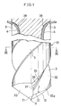
- the shank 10 of a drill has helical flutes 3 for discharging chips therethrough and a conical end, which is formed with a pair of cutting edges 2 arranged in point symmetry and extending from the center of rotation, O, of the drill to the outer periphery of the shank 10.
- Each of the cutting edges 2 comprises an edge portion 21 providing a chisel portion and an edge portion 22 extending from the portion 21 toward the periphery.
- These edge portions 21 and 22 are generally straight and in a V-shaped arrangement with an obtuse angle formed therebetween at the junction when seen in a bottom view.
- the edge portions 21,22 may be curved forward or rearward with respect to the direction of rotation of the drill.
- the end face of the shank 10 comprises a flank 13 having the cutting edge 2, and a land portion 20 in the form of a slanting surface and positioned in the rear of the flank 13 with respect to the direction of rotation.
- Each of the flutes 3 is approximately L-shaped in cross section and defined by a wall 31 positioned forward with respect to the direction of rotation and a wall 32 positioned rearward with respect to the direction at an angle of 90 degrees with the wall 31.
- This angle is variable within the range of 70 to 120 degrees, preferably within the range of 85 to 100 degrees. If the angle is greater than this range, the chip will not be prevented from curling by being pressed against the flute defining wall as will be described later, whereas if the angle is smaller than the range, it is difficult to form the flute.
- the forward wall 31 is recessed (by being cut away) so that the peripheral side of the flute 3 is enlaged forward with respect to the direction of rotation. More specifically, the forward wall 31 has a projection 33, and beyond this position toward the periphery, the wall 31 is recessed to provide a wall 35. Instead of forming the wall 35, a slanting wall 39 may be formed so as to increase the width of the flute toward the periphery. As shown in Fig. 1, the projection 33 continuously extends approximately centrally of the flute 3.
- the flutes 3 have a depth A 0.25 to 0.40 times the diameter D of the shank 10. If the depth A is smaller than this range, difficulty is encountered in discharging chips, whereas deeper flutes impair the rigidity of the shank 10.
- the depth A of the illustrated flutes is 0.25 times the diameter D of the drill.
- the peripheral enlarged portion of the flute 3 has a dimension B which is about 0.15 D and a dimension C which is about 0.1D.
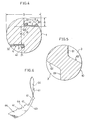
- Fig. 4 shows another embodiment of the invention which has the same construction as above in that the flute 3 thereof is defined by walls 31 and 32 intersecting each other at a right angle but differs from the first embodiment in that the wall 31 has no projection 33 and extends to the periphery of the shank.
- the walls 31 and 32 defining the flute 3 are each straight in cross section and make an angle of 90 degrees therebetween. However, these walls can be modified variously as shown in Figs. 5 to 10.
- a wall 61 forward with respect to the direction of rotation of the drill is at an angle of 120 degrees with a rearward wall 62.
- the ealls 61, 62 are each straight in cross section.
- the chip 4 comprises small curl portions 41 formed by the portion of the cutting edge 2 close to the center of the drill, and a flat plate portion 40 formed by the other portion of the edge 2 toward the drill periphery.
- the curl portions 41 extend from one side of the plate portion integrally therewith and are arranged discretely longitudinally of the plate portion 40, with cracks 44 formed in the side part.
- the chip 4 thus shaped is produced in the following manner.
- the flat plate portion 40 formed by the outer portion (edge portion 22) of the cutting edge 2 and forced into the flute 3 has its one side pressed against the base portion of the wall 31, with the planar part of the plate portion 40 pressed against the wall 32, whereby the chip 4 is prevented from curling in its entirety.
- the chip is subjected to plastic deformation by the cutting action and further plastically deformed by being stretched by its outer portion. Consequently, the chip in the form of a flat strip with cracks 44 formed in the side part thereof is forced upward through the flute 3.
- the chip thus moving upward along the gentle helical shape of the flute 3 egresses from the drilled bore and fractured at the cracked portions 44 by a centrifugal force.
- the chip is bent outward by a curved fluted portion 38 at the upper end of the flute as seen in Fig. 1, with the result that the chip 4 made brittle by cracking and marked plastic deformation is broken into fragments.
- the chip 4 formed by the drill of the construction shown in Figs. 1 to 3 is forced upward into the flute 3 with the flat plate portion 40 initially pressed by the rake face 32a and with the side part pressed against the wall 31.
- the side outer portion of the chip 4 then moves to the enlarged flute portion defined by the wall 35 as seen in Fig. 3.
- the wall 31 acts to prevent the chip from curling by pressing contact with the side part of the flat plate portion 40
- the enlarged flute portion provided by the wall 35 positioned outward from the wall 31 thus facilitates passage of the chip.
- the drill exhibits the advantage of smoothly discharging chips 4.
- the chip 4 has its flat plate portion 40 pressed against the wall 62, with one edge thereof in contact with the base portion of the wall 61, whereby the chip 4 in the flute 3 is prevented from curling in its entirety before discharge.
- the chip 4 can be discharged in the form of a flat strip without curling in its entirety within the flute 3, so that the flute 3 need not have a large depth.
- This increases the core thickness (the dimension between the deepest portions of the flutes) ⁇ (see Fig. 4) of the shank 10 to thereby give improved rigidity to the shank, consequently precluding the axis of the drill from deflecting during drilling.
- flutes 3 formed in the shanks of the foregoing embodiments are all helical, such flutes need not always be helical but can be straight.
- the chip is prevented from curling and plastically deformed by the flute defining walls, continuously discharged in the form of a flat plate and fractured by a centrifugal force when projecting from the drilled hole by a predetermined amount. Further when the drilled bore is deep, the chip is bent outward at the upper end of the flute and thereby fractured. The chip extends continuously through the flute and can therefore be discharged smoothly without clogging the flute even during deep hole drilling.
- the reduced depth of the flute gives improved rigidity to the shank, consequently rendering the drill operable with a high efficiency and high accuracy even for deep hole drilling and easily usable at a high feed speed. Since oil can be supplied through the flute from outside, the drill has the advantage that there is no need to form an oil supply opening in the drill.
Landscapes
- Engineering & Computer Science (AREA)
- Mechanical Engineering (AREA)
- Drilling Tools (AREA)
Description
- The present invention relates to drills comprising the features of the preamble of claim 1 (cf. transactions of the ASME, February 1957, page 227). Such drills are suitable for deep hole drilling and have helical or straight flutes formed in the shank for discharging chips therethrough.
- Generally, drills are formed with helical flutes in the shank for discharging chips. The chips are curled while moving through the flutes and are discharged in the form of conical helical chips. Such discharged chips revolve with the rotation of the drill, wind around neighboring portions of the drilling apparatus and therefore cause trouble when the apparatus is operated automatically continuously in the absence of the operator. Attempts are also made to cause drills to produce chips in the form of small fragments instead of forming continuous chips. Further to discharge chips smoothly, conventional drills are formed with enlarged flutes for curled chips to pass therethrough easily.
- In the case where chips are thus discharged as curled, there arises the problem that the chips are cumbersome to remove. Especially, deep hole drilling encounters the problem that chips clog up the flute without being discharged smoothly to make it impossible to conduct the drilling operation.
- Further when large flutes are formed to discharge chips smoothly, there arises the problem that the shank has reduced torsional rigidity, failing to drill holes efficiently.
- Deep hole drilling, which involves the necessity of supplying oil to the cutting portion, encounters another problem. When the oil is supplied through the flute from outside, the chip moves up while curling to the shape of a funnel to scoop up the oil supplied to the flute, with the result that the oil fails to reach the cutting portion. To overcome this problem, conventional twist drills are produced by a complex method, ie. by forming an axial bore in a shank, then twisting the shank and forming oil supply ports.
- A drill according to the present invention comprises a shank with helical or straight flutes for discharging chips therethrough, each said flute having walls which are respectively positioned forward and rearward with respect to the direction of rotation of the drill, a pair of cutting edges formed at one end of the shank each extending from the centre of the drill to its periphery, each said cutting edge being formed with a rake face over the length of said edge, the flutes having a depth 0.25 to 0.40 times the diameter of the drill and being approximately L-shaped in cross-section with their forward and rearward walls at an angle of 70 to 120° relative to each other, the rearward walls being arranged to be engaged by a portion of the chip formed by an outer peripheral portion of the cutting edge, and the forward walls of the flutes being arranged to limit the curling of the chips.
- By providing a drill having flutes approximately L-shaped in cross-section, it is possible to arrange for the chips to be discharged smoothly while being prevented from continuously curling, without the necessity of forming the flutes to a greater depth, even for use in deep hole drilling. By limiting the curling of the chips, they are encouraged to break spontaneously when emerging from the hole formed by the drill or when leaving the drill.
- The forward wall of each flute may be recessed so that the peripheral side of the flute is enlarged forwards with respect to the direction of rotation.
- A form of drill proposed in the article "Some Experiments in the Influence of Various Factors on Drill Performance" (Transactions of the ASME, February 1957, page 191) has flutes with a depth of some 0.3 times the diameter of the drill and a convexly-curved approximately U-shape cross-section. Central cutting edge portions extend inwards from outer cutting edge portions at the tip of the drill, in place of the conventional chisel edge, to give a cutting edge extending from the centre of the drill to its periphery and formed with a rake face over its length. While this special tip formation of the drill enhances its cutting ability, the drill is otherwise conventional in the chips it produces will take a continuous curled form.
- In the use of a drill embodying the present invention, a chip formed by the drill is prevented from curling by the flute-defining walls. The portion of the chip toward the center is plastically deformed by being stretched by the outer portion of the chip, and the chip is continuously discharged in the form of a flat plate from the hole or bore formed. The chip is fractured by being bent by centrifugal force and the upper end of the fluted portion. The chip is in the form of a continuous piece while passing through the flute and is therefore smoothly dischargeable without clogging the flute even when the drill is used for deep hole drilling.
- Since the chip does not curl, oil can be readily supplied to the cutting portion through the flutes.
- Preferred embodiments of the invention will be described by way of example with reference to the accompanying drawings, in which:
- Fig. 1 is a side elevation partly broken away and showing a drill embodying the invention;
- Fig. 2 is a bottom view of the same;
- Fig. 3 is a view in section taken along the line III-III in Fig. 1;
- Figs. 4 and 5 are views corresponding to Fig. 3 and showing further embodiments of the invention; and
- Fig. 6 is a perspective view of a chip formed by the drill.
- With reference to Figs. 1 to 3, the
shank 10 of a drill hashelical flutes 3 for discharging chips therethrough and a conical end, which is formed with a pair ofcutting edges 2 arranged in point symmetry and extending from the center of rotation, O, of the drill to the outer periphery of theshank 10. Each of thecutting edges 2 comprises anedge portion 21 providing a chisel portion and anedge portion 22 extending from theportion 21 toward the periphery. Theseedge portions edge portions - The end face of the
shank 10 comprises aflank 13 having thecutting edge 2, and aland portion 20 in the form of a slanting surface and positioned in the rear of theflank 13 with respect to the direction of rotation. - Each of the
flutes 3 is approximately L-shaped in cross section and defined by awall 31 positioned forward with respect to the direction of rotation and awall 32 positioned rearward with respect to the direction at an angle of 90 degrees with thewall 31. This angle is variable within the range of 70 to 120 degrees, preferably within the range of 85 to 100 degrees. If the angle is greater than this range, the chip will not be prevented from curling by being pressed against the flute defining wall as will be described later, whereas if the angle is smaller than the range, it is difficult to form the flute. - The
forward wall 31 is recessed (by being cut away) so that the peripheral side of theflute 3 is enlaged forward with respect to the direction of rotation. More specifically, theforward wall 31 has aprojection 33, and beyond this position toward the periphery, thewall 31 is recessed to provide awall 35. Instead of forming thewall 35, aslanting wall 39 may be formed so as to increase the width of the flute toward the periphery. As shown in Fig. 1, theprojection 33 continuously extends approximately centrally of theflute 3. - Preferably, the
flutes 3 have a depth A 0.25 to 0.40 times the diameter D of theshank 10. If the depth A is smaller than this range, difficulty is encountered in discharging chips, whereas deeper flutes impair the rigidity of theshank 10. The depth A of the illustrated flutes is 0.25 times the diameter D of the drill. The peripheral enlarged portion of theflute 3 has a dimension B which is about 0.15 D and a dimension C which is about 0.1D. - Fig. 4 shows another embodiment of the invention which has the same construction as above in that the
flute 3 thereof is defined bywalls wall 31 has noprojection 33 and extends to the periphery of the shank. - The
walls flute 3 are each straight in cross section and make an angle of 90 degrees therebetween. However, these walls can be modified variously as shown in Figs. 5 to 10. - With reference to Fig. 5, a
wall 61 forward with respect to the direction of rotation of the drill is at an angle of 120 degrees with arearward wall 62. Theealls - When the drill is used for forming a hole or bore,
chips 4 as shown in Fig. 6 are produced. Thechip 4 comprisessmall curl portions 41 formed by the portion of thecutting edge 2 close to the center of the drill, and aflat plate portion 40 formed by the other portion of theedge 2 toward the drill periphery. Thecurl portions 41 extend from one side of the plate portion integrally therewith and are arranged discretely longitudinally of theplate portion 40, withcracks 44 formed in the side part. - The
chip 4 thus shaped is produced in the following manner. With reference to Fig. 4, theflat plate portion 40 formed by the outer portion (edge portion 22) of thecutting edge 2 and forced into theflute 3 has its one side pressed against the base portion of thewall 31, with the planar part of theplate portion 40 pressed against thewall 32, whereby thechip 4 is prevented from curling in its entirety. (The chip is subjected to plastic deformation by the cutting action and further plastically deformed by being stretched by its outer portion. Consequently, the chip in the form of a flat strip withcracks 44 formed in the side part thereof is forced upward through theflute 3. The chip thus moving upward along the gentle helical shape of theflute 3 egresses from the drilled bore and fractured at the crackedportions 44 by a centrifugal force. When the bore drilled is deep, the chip is bent outward by a curvedfluted portion 38 at the upper end of the flute as seen in Fig. 1, with the result that thechip 4 made brittle by cracking and marked plastic deformation is broken into fragments. - The
chip 4 formed by the drill of the construction shown in Figs. 1 to 3 is forced upward into theflute 3 with theflat plate portion 40 initially pressed by therake face 32a and with the side part pressed against thewall 31. The side outer portion of thechip 4 then moves to the enlarged flute portion defined by thewall 35 as seen in Fig. 3. This assures smooth discharge of thechip 4. While thewall 31 acts to prevent the chip from curling by pressing contact with the side part of theflat plate portion 40, the enlarged flute portion provided by thewall 35 positioned outward from thewall 31 thus facilitates passage of the chip. Especially when the drill is used for deep hole drilling, the drill exhibits the advantage of smoothly dischargingchips 4. - With the structure shown in Fig. 5, the
chip 4 has itsflat plate portion 40 pressed against thewall 62, with one edge thereof in contact with the base portion of thewall 61, whereby thechip 4 in theflute 3 is prevented from curling in its entirety before discharge. - According to the embodiments of the invention described above, the
chip 4 can be discharged in the form of a flat strip without curling in its entirety within theflute 3, so that theflute 3 need not have a large depth. This increases the core thickness (the dimension between the deepest portions of the flutes) α (see Fig. 4) of theshank 10 to thereby give improved rigidity to the shank, consequently precluding the axis of the drill from deflecting during drilling. - The embodiments described above are free of the likelihood that the chip to be discharged will not scoop up the oil supplied to the flute. This makes it possible to supply oil through the flute from outside and therefore results in the advantage that an oil supply opening need not be formed in the drill.
- Although the
flutes 3 formed in the shanks of the foregoing embodiments are all helical, such flutes need not always be helical but can be straight. - With the embodiments of the present invention described above, the chip is prevented from curling and plastically deformed by the flute defining walls, continuously discharged in the form of a flat plate and fractured by a centrifugal force when projecting from the drilled hole by a predetermined amount. Further when the drilled bore is deep, the chip is bent outward at the upper end of the flute and thereby fractured. The chip extends continuously through the flute and can therefore be discharged smoothly without clogging the flute even during deep hole drilling.
- The reduced depth of the flute gives improved rigidity to the shank, consequently rendering the drill operable with a high efficiency and high accuracy even for deep hole drilling and easily usable at a high feed speed. Since oil can be supplied through the flute from outside, the drill has the advantage that there is no need to form an oil supply opening in the drill.
Claims (9)
- A drill comprising:
a shank (10) with helical or straight flutes (3) for discharging chips therethrough;
each said flute having walls (31,32) which are respectively positioned forward and rearward with respect to the direction of rotation of the drill;
a pair of cutting edges (2) formed at one end of the shank;
each said cutting edge extending from the centre (O) of the drill to the periphery of the drill;
each said cutting edge being formed with a rake face over the length of the edge;
each flute (3) having a depth 0.25 to 0.40 times the diameter of the drill and its rearward wall being arranged to be engaged by a portion of the chip formed by an outer peripheral portion of the cutting edge;
characterised in that the flutes are approximately L-shaped in cross-section with their forward and rearward walls (31,32) at an angle of 70 to 120 degrees relative to each other, and the forward walls (31) of the flutes are arranged to limit the curling of the chips. - A drill according to claim 1, wherein the flutes are arranged to form the cutting chips produced by the cutting edges in a generally flattened shape.
- A drill according to claim 1 or claim 2, wherein the forward and rearward walls extend from a juncture of said walls to the periphery of the drill and the length of the rearward wall (32) from said juncture to the periphery is greater than that of the forward wall (31).
- A drill according to any one of claims 1 to 3, wherein each said forward wall lies generally parallel to a diameter of the drill.
- A drill according to any one of claims 1 to 3, wherein at least a portion of each said forward wall lies on a diameter of the drill.
- A drill according to any one of the preceding claims, wherein each said rearward wall is generally perpendicular to its associated forward wall.
- A drill according to any one of the preceding claims, wherein each said rearward wall (32) is generally linear in radial cross-section.
- A drill according to any one of the preceding claims, wherein said forward wall (31) has radially inner and outer portions (33; 35,39), and the outer portion (35,39) is positioned forwardly relative to the inner portion.
- A drill according to any one of the preceding claims, wherein at least a portion of said forward wall (31) is generally linear in radial cross-section.
Applications Claiming Priority (4)
| Application Number | Priority Date | Filing Date | Title |
|---|---|---|---|
| JP58974/88 | 1988-03-11 | ||
| JP5897488 | 1988-03-11 | ||
| JP89568/88 | 1988-04-12 | ||
| JP63089568A JP2603993B2 (en) | 1988-03-11 | 1988-04-12 | Drill |
Publications (3)
| Publication Number | Publication Date |
|---|---|
| EP0332437A2 EP0332437A2 (en) | 1989-09-13 |
| EP0332437A3 EP0332437A3 (en) | 1990-08-08 |
| EP0332437B1 true EP0332437B1 (en) | 1995-12-13 |
Family
ID=26399989
Family Applications (1)
| Application Number | Title | Priority Date | Filing Date |
|---|---|---|---|
| EP89302336A Expired - Lifetime EP0332437B1 (en) | 1988-03-11 | 1989-03-09 | Drill |
Country Status (6)
| Country | Link |
|---|---|
| US (2) | US5004384A (en) |
| EP (1) | EP0332437B1 (en) |
| JP (1) | JP2603993B2 (en) |
| KR (1) | KR950006363B1 (en) |
| CA (1) | CA1308579C (en) |
| DE (1) | DE68925049T2 (en) |
Families Citing this family (22)
| Publication number | Priority date | Publication date | Assignee | Title |
|---|---|---|---|---|
| US5323823A (en) * | 1992-12-11 | 1994-06-28 | Roto Zip Tool Corporation | Wood router bit |
| US5609447A (en) * | 1993-11-15 | 1997-03-11 | Rogers Tool Works, Inc. | Surface decarburization of a drill bit |
| US5628837A (en) * | 1993-11-15 | 1997-05-13 | Rogers Tool Works, Inc. | Surface decarburization of a drill bit having a refined primary cutting edge |
| ATE208675T1 (en) * | 1996-02-29 | 2001-11-15 | Komet Stahlhalter Werkzeug | DRILLING TOOL FOR MACHINE TOOLS AND METHOD FOR THE PRODUCTION THEREOF |
| US6916139B2 (en) | 2001-07-10 | 2005-07-12 | Mitsubishi Materials Corporation | Drill |
| JP2005186247A (en) * | 2003-12-26 | 2005-07-14 | Dijet Ind Co Ltd | Twist drill |
| EP1992437A4 (en) * | 2006-02-23 | 2011-07-06 | Univ Tokyo Agriculture & Technology Tlo Co Ltd | NON AXISYMETRIC BLADE DRILL |
| US7546786B2 (en) * | 2006-04-04 | 2009-06-16 | Kennametal Inc. | Toolholder with chip ejection segment thereupon |
| SE531188C2 (en) * | 2007-05-29 | 2009-01-13 | Sandvik Intellectual Property | Drill body for chip separating machining |
| CN103313667B (en) * | 2010-11-26 | 2016-04-20 | 希皮尔控股私人有限公司 | drill |
| JP5762547B2 (en) * | 2011-09-06 | 2015-08-12 | オーエスジー株式会社 | drill |
| WO2013065201A1 (en) | 2011-11-04 | 2013-05-10 | オーエスジー株式会社 | Drill |
| DE102012012479A1 (en) * | 2012-03-26 | 2013-09-26 | MAPAL Fabrik für Präzisionswerkzeuge Dr. Kress KG | drill |
| US9232952B2 (en) | 2012-04-16 | 2016-01-12 | Medtronic Ps Medical, Inc. | Surgical bur with non-paired flutes |
| US9883873B2 (en) | 2013-07-17 | 2018-02-06 | Medtronic Ps Medical, Inc. | Surgical burs with geometries having non-drifting and soft tissue protective characteristics |
| US10335166B2 (en) | 2014-04-16 | 2019-07-02 | Medtronics Ps Medical, Inc. | Surgical burs with decoupled rake surfaces and corresponding axial and radial rake angles |
| US9955981B2 (en) | 2015-03-31 | 2018-05-01 | Medtronic Xomed, Inc | Surgical burs with localized auxiliary flutes |
| US10265082B2 (en) * | 2015-08-31 | 2019-04-23 | Medtronic Ps Medical, Inc. | Surgical burs |
| DE112018002739T5 (en) * | 2017-05-29 | 2020-03-05 | Kyocera Corporation | Drill and method of making a machined product |
| WO2019244106A1 (en) | 2018-06-22 | 2019-12-26 | Maestro Logistics, Llc | A drill bit and method for making a drill bit |
| WO2022179709A1 (en) | 2021-02-26 | 2022-09-01 | Gripp-X B.V. | Drill bit |
| US20250127522A1 (en) * | 2023-10-24 | 2025-04-24 | Medtronic Ps Medical, Inc. | Surgical bur with improved cutting and method of improving cutting effectiveness |
Family Cites Families (16)
| Publication number | Priority date | Publication date | Assignee | Title |
|---|---|---|---|---|
| US465392A (en) * | 1891-12-15 | Island | ||
| US750537A (en) * | 1904-01-26 | Drilling-tool | ||
| DE159437C (en) * | ||||
| US1069930A (en) * | 1912-04-23 | 1913-08-12 | William R Down | Drill. |
| BE524021A (en) * | 1951-10-12 | |||
| US2936658A (en) * | 1956-08-08 | 1960-05-17 | Oscar L Riley | Twist drill |
| US2966081A (en) * | 1959-03-18 | 1960-12-27 | United Greenfield Corp | Drill |
| DE2043316A1 (en) * | 1970-08-25 | 1972-03-02 | Stock Ag R | Liquid-cooled twist drill |
| US4222690A (en) * | 1977-12-03 | 1980-09-16 | Ryosuke Hosoi | Drill having cutting edges with the greatest curvature at the central portion thereof |
| DE3131794C2 (en) * | 1980-08-29 | 1986-08-07 | Toshiaki Osaka Hosoi | drill |
| JPS58177214A (en) * | 1982-04-08 | 1983-10-17 | Fuji Seikou Kk | Drill |
| US4605347A (en) * | 1982-12-27 | 1986-08-12 | Lockheed Missiles & Space Company, Inc. | High speed drill reamer |
| JPS59219108A (en) * | 1983-05-25 | 1984-12-10 | Sumitomo Electric Ind Ltd | Drill |
| JPS60177807A (en) * | 1984-02-20 | 1985-09-11 | Toshiaki Hosoi | Drill |
| JPS61178110A (en) * | 1985-02-01 | 1986-08-09 | Toshiaki Hosoi | Drill |
| JPS634211U (en) * | 1986-06-23 | 1988-01-12 |
-
1988
- 1988-04-12 JP JP63089568A patent/JP2603993B2/en not_active Expired - Lifetime
-
1989
- 1989-03-06 US US07/319,582 patent/US5004384A/en not_active Expired - Fee Related
- 1989-03-08 CA CA000593121A patent/CA1308579C/en not_active Expired - Lifetime
- 1989-03-08 KR KR1019890002836A patent/KR950006363B1/en not_active Expired - Fee Related
- 1989-03-09 EP EP89302336A patent/EP0332437B1/en not_active Expired - Lifetime
- 1989-03-09 DE DE68925049T patent/DE68925049T2/en not_active Expired - Fee Related
-
1990
- 1990-03-21 US US07/497,178 patent/US4975003A/en not_active Expired - Lifetime
Non-Patent Citations (1)
| Title |
|---|
| Transactions of the ASME, February 1957, page 227 * |
Also Published As
| Publication number | Publication date |
|---|---|
| JPH0230414A (en) | 1990-01-31 |
| KR890014195A (en) | 1989-10-23 |
| US5004384A (en) | 1991-04-02 |
| DE68925049T2 (en) | 1996-07-04 |
| DE68925049D1 (en) | 1996-01-25 |
| EP0332437A2 (en) | 1989-09-13 |
| CA1308579C (en) | 1992-10-13 |
| US4975003A (en) | 1990-12-04 |
| KR950006363B1 (en) | 1995-06-14 |
| JP2603993B2 (en) | 1997-04-23 |
| EP0332437A3 (en) | 1990-08-08 |
Similar Documents
| Publication | Publication Date | Title |
|---|---|---|
| EP0332437B1 (en) | Drill | |
| RU2452597C2 (en) | Drill bit point | |
| KR100379345B1 (en) | Drilling tools for solid metal drilling | |
| US4452554A (en) | Annular hole cutter | |
| EP1250206B1 (en) | Spade drill insert and spade drill with chip control geometry | |
| US9168601B2 (en) | Multi-flute reamer and cutting insert therefor | |
| EP0043771B1 (en) | Tool for generating holes in composite materials | |
| US4871287A (en) | Annular cutter having radial clearance | |
| JPWO2009142323A1 (en) | Drill, cutting insert and method of manufacturing workpiece | |
| JPS62188616A (en) | Rotary cutting tool | |
| JPH10109210A (en) | Indexable insert for spade drill | |
| EP2277648A1 (en) | Deep-hole boring drill head | |
| JP3988659B2 (en) | Drill | |
| US5240357A (en) | Annular hole cutter | |
| US4400119A (en) | Twist drill | |
| JP4088271B2 (en) | Cutting tools | |
| JP4384327B2 (en) | Drill insert | |
| JPH07124809A (en) | Core drill provided with cutting chip discharge hole | |
| GB2080162A (en) | Annular hole cutter | |
| KR102164828B1 (en) | Drill and Insert thereof Improving Centering Ability and Cutting Performance | |
| JP2020175465A (en) | Drill | |
| JP2005177891A (en) | drill | |
| RU2771284C2 (en) | Drilling insert | |
| JP4608933B2 (en) | Drills, throwaway drills and throwaway tips | |
| JP4055141B2 (en) | Drills, throwaway drills and throwaway tips |
Legal Events
| Date | Code | Title | Description |
|---|---|---|---|
| PUAI | Public reference made under article 153(3) epc to a published international application that has entered the european phase |
Free format text: ORIGINAL CODE: 0009012 |
|
| AK | Designated contracting states |
Kind code of ref document: A2 Designated state(s): DE FR GB IT SE |
|
| PUAL | Search report despatched |
Free format text: ORIGINAL CODE: 0009013 |
|
| RHK1 | Main classification (correction) |
Ipc: B23B 51/02 |
|
| AK | Designated contracting states |
Kind code of ref document: A3 Designated state(s): DE FR GB IT SE |
|
| 17P | Request for examination filed |
Effective date: 19901020 |
|
| 17Q | First examination report despatched |
Effective date: 19911223 |
|
| GRAA | (expected) grant |
Free format text: ORIGINAL CODE: 0009210 |
|
| AK | Designated contracting states |
Kind code of ref document: B1 Designated state(s): DE FR GB IT SE |
|
| REF | Corresponds to: |
Ref document number: 68925049 Country of ref document: DE Date of ref document: 19960125 |
|
| ITF | It: translation for a ep patent filed | ||
| ET | Fr: translation filed | ||
| PLBE | No opposition filed within time limit |
Free format text: ORIGINAL CODE: 0009261 |
|
| STAA | Information on the status of an ep patent application or granted ep patent |
Free format text: STATUS: NO OPPOSITION FILED WITHIN TIME LIMIT |
|
| 26N | No opposition filed | ||
| REG | Reference to a national code |
Ref country code: GB Ref legal event code: IF02 |
|
| PGFP | Annual fee paid to national office [announced via postgrant information from national office to epo] |
Ref country code: GB Payment date: 20040309 Year of fee payment: 16 |
|
| PGFP | Annual fee paid to national office [announced via postgrant information from national office to epo] |
Ref country code: FR Payment date: 20040319 Year of fee payment: 16 |
|
| PGFP | Annual fee paid to national office [announced via postgrant information from national office to epo] |
Ref country code: DE Payment date: 20040324 Year of fee payment: 16 |
|
| PGFP | Annual fee paid to national office [announced via postgrant information from national office to epo] |
Ref country code: SE Payment date: 20040329 Year of fee payment: 16 |
|
| PG25 | Lapsed in a contracting state [announced via postgrant information from national office to epo] |
Ref country code: IT Free format text: LAPSE BECAUSE OF NON-PAYMENT OF DUE FEES;WARNING: LAPSES OF ITALIAN PATENTS WITH EFFECTIVE DATE BEFORE 2007 MAY HAVE OCCURRED AT ANY TIME BEFORE 2007. THE CORRECT EFFECTIVE DATE MAY BE DIFFERENT FROM THE ONE RECORDED. Effective date: 20050309 Ref country code: GB Free format text: LAPSE BECAUSE OF NON-PAYMENT OF DUE FEES Effective date: 20050309 |
|
| PG25 | Lapsed in a contracting state [announced via postgrant information from national office to epo] |
Ref country code: SE Free format text: LAPSE BECAUSE OF NON-PAYMENT OF DUE FEES Effective date: 20050310 |
|
| PG25 | Lapsed in a contracting state [announced via postgrant information from national office to epo] |
Ref country code: DE Free format text: LAPSE BECAUSE OF NON-PAYMENT OF DUE FEES Effective date: 20051001 |
|
| EUG | Se: european patent has lapsed | ||
| GBPC | Gb: european patent ceased through non-payment of renewal fee |
Effective date: 20050309 |
|
| PG25 | Lapsed in a contracting state [announced via postgrant information from national office to epo] |
Ref country code: FR Free format text: LAPSE BECAUSE OF NON-PAYMENT OF DUE FEES Effective date: 20051130 |
|
| REG | Reference to a national code |
Ref country code: FR Ref legal event code: ST Effective date: 20051130 |