EP0332432A2 - Logarithmischer Verstärker - Google Patents
Logarithmischer Verstärker Download PDFInfo
- Publication number
- EP0332432A2 EP0332432A2 EP89302325A EP89302325A EP0332432A2 EP 0332432 A2 EP0332432 A2 EP 0332432A2 EP 89302325 A EP89302325 A EP 89302325A EP 89302325 A EP89302325 A EP 89302325A EP 0332432 A2 EP0332432 A2 EP 0332432A2
- Authority
- EP
- European Patent Office
- Prior art keywords
- amplifier
- distributed
- logarithmic
- logarithmic amplifier
- transmission line
- Prior art date
- Legal status (The legal status is an assumption and is not a legal conclusion. Google has not performed a legal analysis and makes no representation as to the accuracy of the status listed.)
- Withdrawn
Links
Images
Classifications
-
- G—PHYSICS
- G06—COMPUTING OR CALCULATING; COUNTING
- G06G—ANALOGUE COMPUTERS
- G06G7/00—Devices in which the computing operation is performed by varying electric or magnetic quantities
- G06G7/12—Arrangements for performing computing operations, e.g. operational amplifiers
- G06G7/24—Arrangements for performing computing operations, e.g. operational amplifiers for evaluating logarithmic or exponential functions, e.g. hyperbolic functions
Definitions
- Logarithmic amplifiers which are amplifiers having a logarithmic transfer characteristic, are used widely and one example of their use is in microwave instrumentation.
- At present logarithmic amplifiers comprise a number of amplifiers having a linear characteristic connected sequentially via hybrid couplers.
- Each of the hybrid couplers is connected to a demodulator for demodulating an amplitude modulated signal and these are commonly known as video detectors.
- the outputs from all of the demodulators are then summed to provide the logarithmic output of the amplifier.
- a logarithmic amplifier comprises a series of MESFET distributed amplifiers connected in cascade, each having a substantially linear transfer characteristic, an input for the logarithmic amplifier being connected to an input end of the gate transmission line of a first distributed amplifier and the output end of the gate transmission line of each distributed amplifier being terminated by a demodulator for demodulating amplitude modulation, and summing means connected to the output of each of the demodulators to sum their outputs and thereby provide the output of the logarithmic amplifier.
- each demodulator includes a simple rectifier formed by a pn junction.
- the demodulator acts non-linearly it rectifies and produces a rectified output which is a DC voltage for a constant carrier wave signal or a demodulated signal for an amplitude modulated carrier wave, which for each amplifier, is invariant.
- Each demodulator may also include a low pass circuit connected downstream of its rectifier.
- the gate transmission line of each amplifier may include a resistive load matched to the characteristic impedance of the gate transmission line or, alternatively, the corresponding demodulator may have an impedance equivalent to that of the gate transmission line and so replace the impedance matching resistor of the gate transmission line.
- the summer is preferably formed by an operational amplifier having the outputs from each of the demodulators connected to its input.
- MESFET distributed amplifiers have a very broad bandwidth and accordingly a logarithmic amplifier in accordance with this invention is capable of handling pulses having a very short rise time of the order tens of pico seconds.
- GaAs MESFET distributed amplifiers capable of handling signals from 20 MHz to 50 GHz are relatively cheap and can be readily formed as a monolithic integrated circuit or a hybrid integrated circuit in which all of the components are manufactured separately and then mounted on a microwave substrate.
- the number of distributed amplifiers connected in cascade depends upon the required dynamic range of the logarithmic amplifier. Typically distributed amplifiers including, for example, four GaAs MESFETs have a gain of between 6 and 10 dB. Thus, for a logarithmic amplifier to have a dynamic range of 70 dB, between 7 and 12 distributed amplifiers are connected together in cascade. Usually 8 or 9 are connected together.
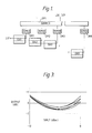
- This example of a logarithmic amplifier includes eight distributed amplifiers DA1 to DA8 connected together in cascade. Each distributed amplifier DA1 to DA8 has a demodulator DM1 to DM8 associated with its gate transmission line and the outputs of these are connected to a summer OP1.
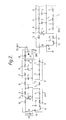
- Each distributed amplifier includes four GaAs MESFETs 1 to 4 with their gate electrodes g connected to a gate transmission line G, their drain electrodes d connected to a drain transmission line D and their source electrodes s connected to a ground plane 5.
- An input 6 to the first distributed amplifier DA1 forms the input to the logarithmic amplifier.
- the gate transmission lines G include inductors 8 connected between the gate electrodes of successive transistors 1, 2, 3 and 4 and inductors 10 in the end sections of the line.
- the drain transmission line D includes inductors 9 connected between the drain electrodes of adjacent transistors 1, 2, 3 and 4 and inductors 11 in the end sections of the line.
- the gate transmission line G is terminated at its right hand end, as seen in Figure 2 by a resistor 12 which matches the characteristic impedance of the line.
- the left hand side of the gate transmission line is terminated by a generator 13 whose signal is to be amplified and which has a source impedance equal to the gate line characteristic impedance.
- the drain transmission line D includes at its left hand end a resistor 14 matching the characteristic impedance of the line.
- a DC source 15 is connected to the source line 5 and to the junction of the resistor 14 and adjacent inductor 11 or the drain transmission line D via a low pass filter 16 to provide bias for the drain electrodes of the transistors 1 to 4.
- a DC blocking capacitor 17 is included at the right end of the drain transmission line D.
- a microwave signal fed into the input 6 is amplified by the successive transistors 1 to 4.
- a respective travelling wave passes along each of the gate G and drain D transmission lines and with each line correctly terminated the gain of the amplifier is substantially independent of the frequency of the microwave signal.
- a gain of 6 dB is obtained.
- the demodulators DM1 to DM8 comprise a diode 18 connected to the right hand end of the gate line G and a low pass filter circuit formed by capacitor 19 and resistor 20 connected in parallel between the gate line G and the source line 5.
- the diode 18 and low pass filter 19 and 20 rectify the travelling wave passing along the gate line G and allow to pass only the amplitude modulation of the travelling wave signal passing along the gate line G and a d.c component of the carrier wave signal. This signal is applied as one input to an eight input summer formed by an operational amplifier OP1.
- the right hand end of the drain transmission line D of distributed amplifier DA1 is connected across the input 6 of distributed amplifier DA2 to connect the amplifiers DA1 and DA2 in cascade. This connection is repeated throughout each of the stages. All of the distributed amplifiers DA1 to DA8 and demodulators DM1 to DM8 are similar except that the right hand end of the drain transmission line D in distributed amplifier DA8 is terminated by an impedance matching resistor (not shown) the resistance of which matches the characteristic impedance of that of the drain transmission line D.
- Figure 3 is a graph illustrating the linearity of a single stage distributed amplifier in accordance with this invention over a dynamic range of 12 dB at frequencies of 2, 3, 4, 5 and 6 GHz. The graph illustrates how the amplifier provides a substantially similar response over this frequency range and a reasonably constant output over the dynamic range.
Landscapes
- Physics & Mathematics (AREA)
- Engineering & Computer Science (AREA)
- Mathematical Physics (AREA)
- Theoretical Computer Science (AREA)
- Software Systems (AREA)
- Computer Hardware Design (AREA)
- General Physics & Mathematics (AREA)
- Microwave Amplifiers (AREA)
- Amplifiers (AREA)
- Tone Control, Compression And Expansion, Limiting Amplitude (AREA)
Applications Claiming Priority (2)
| Application Number | Priority Date | Filing Date | Title |
|---|---|---|---|
| GB888805669A GB8805669D0 (en) | 1988-03-10 | 1988-03-10 | Logarithmic amplifier |
| GB8805669 | 1988-03-10 |
Publications (2)
| Publication Number | Publication Date |
|---|---|
| EP0332432A2 true EP0332432A2 (de) | 1989-09-13 |
| EP0332432A3 EP0332432A3 (de) | 1991-01-30 |
Family
ID=10633161
Family Applications (1)
| Application Number | Title | Priority Date | Filing Date |
|---|---|---|---|
| EP19890302325 Withdrawn EP0332432A3 (de) | 1988-03-10 | 1989-03-09 | Logarithmischer Verstärker |
Country Status (3)
| Country | Link |
|---|---|
| US (1) | US4908529A (de) |
| EP (1) | EP0332432A3 (de) |
| GB (1) | GB8805669D0 (de) |
Families Citing this family (3)
| Publication number | Priority date | Publication date | Assignee | Title |
|---|---|---|---|---|
| US5221907A (en) * | 1991-06-03 | 1993-06-22 | International Business Machines Corporation | Pseudo logarithmic analog step adder |
| US5177381A (en) * | 1991-12-06 | 1993-01-05 | Motorola, Inc. | Distributed logarithmic amplifier and method |
| US5777529A (en) * | 1996-10-10 | 1998-07-07 | Northern Telecom Limited | Integrated circuit assembly for distributed broadcasting of high speed chip input signals |
Family Cites Families (8)
| Publication number | Priority date | Publication date | Assignee | Title |
|---|---|---|---|---|
| US3061789A (en) * | 1958-04-23 | 1962-10-30 | Texas Instruments Inc | Transistorized logarithmic i.f. amplifier |
| US3373294A (en) * | 1964-11-04 | 1968-03-12 | Rca Corp | Linear logarithmic amplifying detector |
| US4209714A (en) * | 1977-06-13 | 1980-06-24 | Trio Kabushiki Kaisha | Logarithmic amplifier |
| DE3279518D1 (en) * | 1981-03-06 | 1989-04-13 | Atomic Energy Authority Uk | Logarithmic amplifiers |
| US4507615A (en) * | 1982-12-16 | 1985-03-26 | Tektronix, Inc. | Non-linear amplifier systems |
| US4720673A (en) * | 1985-05-15 | 1988-01-19 | Avcom Of Virginia, Inc. | Spectrum analyzer and logarithmic amplifier therefor |
| US4812772A (en) * | 1985-05-15 | 1989-03-14 | Avcom Of Virginia, Inc. | Spectrum analyzer and logarithmic amplifier therefor |
| US4853564A (en) * | 1988-05-17 | 1989-08-01 | Texas Instruments Incorporated | GaAs monolithic true logarithmic amplifier |
-
1988
- 1988-03-10 GB GB888805669A patent/GB8805669D0/en active Pending
-
1989
- 1989-03-09 EP EP19890302325 patent/EP0332432A3/de not_active Withdrawn
- 1989-03-09 US US07/321,506 patent/US4908529A/en not_active Expired - Fee Related
Also Published As
| Publication number | Publication date |
|---|---|
| GB8805669D0 (en) | 1988-04-07 |
| US4908529A (en) | 1990-03-13 |
| EP0332432A3 (de) | 1991-01-30 |
Similar Documents
| Publication | Publication Date | Title |
|---|---|---|
| US5933771A (en) | Low voltage gain controlled mixer | |
| US5465415A (en) | Even order term mixer | |
| Pavio et al. | Double balanced mixers using active and passive techniques | |
| JPH1022758A (ja) | 携帯用rf送信端末装置のための温度補償された広い動作範囲の電力検出回路 | |
| JPH01261008A (ja) | 線形増幅兼検波回路装置 | |
| US7205832B2 (en) | Temperature compensated, high efficiency, controlled input impedance diode detector | |
| CA2000670C (en) | Self equalizing multi-stage radio frequency power amplifier | |
| US4355289A (en) | Phase shift and amplitude modulator | |
| Nguyen et al. | A Si bipolar monolithic RF bandpass amplifier | |
| US4430626A (en) | Networks for the log domain | |
| US4410764A (en) | Speech processor for processing analog signals | |
| US5307026A (en) | Variable gain RF amplifier with linear gain control | |
| US4908529A (en) | Logarithmic amplifier comprising MESFET distributed amplifiers connected in cascade | |
| US4885483A (en) | Logarithmic amplifier | |
| US5631594A (en) | Tunable logarithmic amplifier circuit using cascaded triple-tail cells | |
| US5414313A (en) | Dual-mode logarithmic amplifier having cascaded stages | |
| GB1558677A (en) | Fm to am carrier converters | |
| US4375618A (en) | Linearized FM quadrature detector | |
| US4491809A (en) | Matching circuit for a pre-amplifier of SHF band television signal receiver | |
| US4980584A (en) | Multi-stage wideband successive detection logarithmic amplifier | |
| CA1235797A (en) | Device for the automatic precorrection of non- linearities in a power amplification chain for a television transmitter | |
| US6124742A (en) | Wide bandwidth frequency multiplier | |
| US4283693A (en) | Amplitude tilt compensating apparatus | |
| Nawaz et al. | X-band Cascode LNA with Bias-invariant Noise Figure using 0.15 µm GaN-on-SiC Technology | |
| US3753120A (en) | Control signal generating circuit |
Legal Events
| Date | Code | Title | Description |
|---|---|---|---|
| PUAI | Public reference made under article 153(3) epc to a published international application that has entered the european phase |
Free format text: ORIGINAL CODE: 0009012 |
|
| AK | Designated contracting states |
Kind code of ref document: A2 Designated state(s): AT BE CH DE ES FR GB GR IT LI LU NL SE |
|
| PUAL | Search report despatched |
Free format text: ORIGINAL CODE: 0009013 |
|
| AK | Designated contracting states |
Kind code of ref document: A3 Designated state(s): AT BE CH DE ES FR GB GR IT LI LU NL SE |
|
| 17P | Request for examination filed |
Effective date: 19910621 |
|
| STAA | Information on the status of an ep patent application or granted ep patent |
Free format text: STATUS: THE APPLICATION IS DEEMED TO BE WITHDRAWN |
|
| 18D | Application deemed to be withdrawn |
Effective date: 19921001 |