EP0331660B1 - Niederdruckgasentladungslampe - Google Patents
Niederdruckgasentladungslampe Download PDFInfo
- Publication number
- EP0331660B1 EP0331660B1 EP89850075A EP89850075A EP0331660B1 EP 0331660 B1 EP0331660 B1 EP 0331660B1 EP 89850075 A EP89850075 A EP 89850075A EP 89850075 A EP89850075 A EP 89850075A EP 0331660 B1 EP0331660 B1 EP 0331660B1
- Authority
- EP
- European Patent Office
- Prior art keywords
- tube
- fluorescent tube
- lamp
- fluorescent
- outer glass
- Prior art date
- Legal status (The legal status is an assumption and is not a legal conclusion. Google has not performed a legal analysis and makes no representation as to the accuracy of the status listed.)
- Expired - Lifetime
Links
- 239000011521 glass Substances 0.000 claims abstract description 22
- 239000007789 gas Substances 0.000 claims description 14
- 229920000642 polymer Polymers 0.000 claims description 8
- -1 siloxane compound Chemical class 0.000 claims description 8
- 239000000126 substance Substances 0.000 claims description 8
- 239000000463 material Substances 0.000 claims description 4
- 230000008859 change Effects 0.000 claims description 2
- 229910052756 noble gas Inorganic materials 0.000 claims description 2
- 229920001296 polysiloxane Polymers 0.000 claims description 2
- 230000001427 coherent effect Effects 0.000 claims 1
- 230000003301 hydrolyzing effect Effects 0.000 claims 1
- 150000002835 noble gases Chemical class 0.000 claims 1
- KPUWHANPEXNPJT-UHFFFAOYSA-N disiloxane Chemical class [SiH3]O[SiH3] KPUWHANPEXNPJT-UHFFFAOYSA-N 0.000 abstract description 8
- QSHDDOUJBYECFT-UHFFFAOYSA-N mercury Chemical compound [Hg] QSHDDOUJBYECFT-UHFFFAOYSA-N 0.000 abstract description 3
- 229910052753 mercury Inorganic materials 0.000 abstract description 3
- 230000004907 flux Effects 0.000 description 11
- 239000007858 starting material Substances 0.000 description 11
- 238000012360 testing method Methods 0.000 description 10
- 239000003570 air Substances 0.000 description 9
- XLYOFNOQVPJJNP-UHFFFAOYSA-N water Substances O XLYOFNOQVPJJNP-UHFFFAOYSA-N 0.000 description 8
- 230000000694 effects Effects 0.000 description 6
- 238000010438 heat treatment Methods 0.000 description 6
- 238000000034 method Methods 0.000 description 5
- 238000005286 illumination Methods 0.000 description 4
- 239000000178 monomer Substances 0.000 description 4
- OKKJLVBELUTLKV-UHFFFAOYSA-N Methanol Chemical compound OC OKKJLVBELUTLKV-UHFFFAOYSA-N 0.000 description 3
- 230000008901 benefit Effects 0.000 description 3
- 150000002500 ions Chemical class 0.000 description 3
- 239000000203 mixture Substances 0.000 description 3
- 238000006116 polymerization reaction Methods 0.000 description 3
- 230000008569 process Effects 0.000 description 3
- VYPSYNLAJGMNEJ-UHFFFAOYSA-N Silicium dioxide Chemical compound O=[Si]=O VYPSYNLAJGMNEJ-UHFFFAOYSA-N 0.000 description 2
- 239000013543 active substance Substances 0.000 description 2
- 150000001298 alcohols Chemical class 0.000 description 2
- 239000012080 ambient air Substances 0.000 description 2
- 239000011230 binding agent Substances 0.000 description 2
- 150000001875 compounds Chemical class 0.000 description 2
- 238000010276 construction Methods 0.000 description 2
- 238000004519 manufacturing process Methods 0.000 description 2
- 238000007789 sealing Methods 0.000 description 2
- 241000023320 Luma <angiosperm> Species 0.000 description 1
- 229920002319 Poly(methyl acrylate) Polymers 0.000 description 1
- 229910010038 TiAl Inorganic materials 0.000 description 1
- PNEYBMLMFCGWSK-UHFFFAOYSA-N aluminium oxide Inorganic materials [O-2].[O-2].[O-2].[Al+3].[Al+3] PNEYBMLMFCGWSK-UHFFFAOYSA-N 0.000 description 1
- QGZKDVFQNNGYKY-UHFFFAOYSA-O ammonium group Chemical group [NH4+] QGZKDVFQNNGYKY-UHFFFAOYSA-O 0.000 description 1
- 239000011324 bead Substances 0.000 description 1
- 239000002800 charge carrier Substances 0.000 description 1
- 229910052681 coesite Inorganic materials 0.000 description 1
- 229910052593 corundum Inorganic materials 0.000 description 1
- 229910052906 cristobalite Inorganic materials 0.000 description 1
- 230000001419 dependent effect Effects 0.000 description 1
- 239000004205 dimethyl polysiloxane Substances 0.000 description 1
- 239000000428 dust Substances 0.000 description 1
- 239000000975 dye Substances 0.000 description 1
- 238000004880 explosion Methods 0.000 description 1
- 230000008014 freezing Effects 0.000 description 1
- 238000007710 freezing Methods 0.000 description 1
- 229910052809 inorganic oxide Inorganic materials 0.000 description 1
- 238000009413 insulation Methods 0.000 description 1
- 229910052751 metal Inorganic materials 0.000 description 1
- 239000002184 metal Substances 0.000 description 1
- 125000000956 methoxy group Chemical group [H]C([H])([H])O* 0.000 description 1
- 125000002496 methyl group Chemical group [H]C([H])([H])* 0.000 description 1
- OSWPMRLSEDHDFF-UHFFFAOYSA-N methyl salicylate Chemical compound COC(=O)C1=CC=CC=C1O OSWPMRLSEDHDFF-UHFFFAOYSA-N 0.000 description 1
- 230000000485 pigmenting effect Effects 0.000 description 1
- 229920000435 poly(dimethylsiloxane) Polymers 0.000 description 1
- 230000009467 reduction Effects 0.000 description 1
- 238000005057 refrigeration Methods 0.000 description 1
- 230000000630 rising effect Effects 0.000 description 1
- 239000011435 rock Substances 0.000 description 1
- 239000000377 silicon dioxide Substances 0.000 description 1
- 235000012239 silicon dioxide Nutrition 0.000 description 1
- 239000007787 solid Substances 0.000 description 1
- 230000000087 stabilizing effect Effects 0.000 description 1
- 229910052682 stishovite Inorganic materials 0.000 description 1
- 239000013589 supplement Substances 0.000 description 1
- 239000000725 suspension Substances 0.000 description 1
- 229910052905 tridymite Inorganic materials 0.000 description 1
- 229910001845 yogo sapphire Inorganic materials 0.000 description 1
Images

Classifications
-
- H—ELECTRICITY
- H01—ELECTRIC ELEMENTS
- H01J—ELECTRIC DISCHARGE TUBES OR DISCHARGE LAMPS
- H01J61/00—Gas-discharge or vapour-discharge lamps
- H01J61/02—Details
- H01J61/30—Vessels; Containers
- H01J61/34—Double-wall vessels or containers
-
- H—ELECTRICITY
- H01—ELECTRIC ELEMENTS
- H01J—ELECTRIC DISCHARGE TUBES OR DISCHARGE LAMPS
- H01J61/00—Gas-discharge or vapour-discharge lamps
- H01J61/70—Lamps with low-pressure unconstricted discharge having a cold pressure < 400 Torr
- H01J61/72—Lamps with low-pressure unconstricted discharge having a cold pressure < 400 Torr having a main light-emitting filling of easily vaporisable metal vapour, e.g. mercury
Definitions
- the present invention relates to a gas discharge lamp of the tubular kind filled with gas or vapour at low pressure, e.g. a fluorescent lamp.
- a gas discharge lamp of the tubular kind filled with gas or vapour at low pressure e.g. a fluorescent lamp.
- the inventive gas discharge lamp has properties which render it especially suited for use in low ambient temperatures.
- the lamp is therefore particularly suited for outdoor use in the Nordic winter climate, and also for illuminating cold storage and freeze storage facilities.
- Fluorescent lamps are widely used in the open, because the fluorescent lamp gives light more efficiently than an incandescent lamp.
- fluorescent lamps In addition to street lighting, fluorescent lamps have thus been used to illuminate road signs, as canopy lighting, e.g. in railway stations, to illuminate loading piers, loading bays, and gasoline stations, and to an increasing extent as a means of illumination in both freestanding and surface-mounted advertising signs.
- fluorescent lamps, or tubes are used to illuminate signs, and not only to illuminate such signs from within, it is desirable that the luminous flux is uniform
- the document US-A- 3 358 167 discloses a lamp having resilent annular support members attached to each end of the lamp for holding an inner and an outer tube in a spaced relationship.
- the members are not only mechanical distance pads but also a thermal reservoir, which provides additional insulation of the inner tube and especially its end parts, which in turn is described to give the desirable effect that mercury condenses in the cooler center portion of the tube.
- a fluorescent tube which is mounted in known kinds of lamp casings or enclosures will, to some extent, be self-heating, since the air present in the casing is able to conduct heat away from the actual fluorescent tube only to a very limited extent.
- This problem applies to fluorescent tubes incorporated in advertising signs (company name signs) and road signs (traffic), such as overhead lane-destination signs of partially translucent design, and also to fluorescent tubes which are mounted in enclosed lamp fittings. With the ambient air stationary and the air temperature beneath 0°C, this self-heating effect will result in a surface temperature of +15°C on the coldest part of the fluorescent tube.
- the self-heating effect is so small as to produce hardly any increase in luminous flux.
- the lamp casings or enclosures absorb all of the increase in luminous flux achieved by self-heating of the fluorescent tube. Consequently, the great majority of fluorescent lamps for outdoor use are of the kind which have reflectors fitted over the fluorescent tube, but which lack the provision of a casing.
- the purpose of encasing fluorescent lamps is to protect the fluorescent tubes from damage through mechanical causes, and the lighting requirement has been made secondary to the need of protecting the lamp.
- Tunnels are another area of use in which fluorescent tubes or lamps can be subjected to the effects of low ambient temperatures.
- the air flow through tunnels, even when the tunnels have a length of several hundred meters, is so large that any heat which may be radiated from the surrounding rock or earth is unable to supplement heating of the surfaces of the fluorescent tube.
- the luminous flux will decrease exponentially with falling air temperatures. This can have a serious consequence, for instance, on a cold sunny winter's day when a car driver will see the road with an illumination strength of close to 100 000 lux.
- this driver enters an illuminated tunnel his eyes must adjust to an illuminance which is far below 100 lux. Road safety and the driver's own feeling of security are assisted by the fact that the fluorescent lamps in the tunnel maintain a practically normal luminous flux, even in very cold weather conditions.
- the luminous flux is reduced to a third of its original value when the ambient temperature lies within a range of +10°C to 0°C.
- the matter is made more serious by the fact that the luminous flux of a 26 mm tube at +10°C is 20% lower than the luminous flux of a 38 mm tube of corresponding power.
- the starters or chokes normally used are effective in short circuiting the electrodes, so that they are preheated by through surging current, whereby when the striker opens, a spark arcs from anode to cathode and a positive column is generated therebetween.
- the striker will open and close a number of times before the electrodes are sufficiently warm to sustain an arc therebetween. It may often take 30 seconds for the tube to ignite, which drawback is far more manifest in 26 mm tubes than in tubes of 38 mm in diameter.
- the object of the present invention is to solve the problems which are associated with the use of narrow fluorescent tubes in freezing temperatures and to provide a lamp which has high illuminance at low temperatures.
- This object is realized in accordance with the invention with a narrow fluorescent tube which is surrounded along the whole of its length by a fixed transparent outer tube, for instance a glass tube.
- a fixed transparent outer tube for instance a glass tube.
- a gas-discharge lamp which comprises an inner fluorescent tube that is surrounded or enveloped by a glass tube or envelope, which may be transparent or opalescent.
- the ends of this outer tube or envelope are fixed to the cathode-containing ends of the glass tube of the discharge lamp, such as to leave a tubular space of constant width between the outer tube and the inner tube.
- This fixation of the outer glass tube may be effected with the aid of seals located at the ends of the lamp, between the two glass tubes.
- These seals may have the form of polymer sealing rings, or may otherwise comprise age-resistant gas-impermeable material.
- the gas most preferred in this respect is dry, dust-free air, although in particular cases the gas may comprise a noble gas or a mixture of such gases.
- the gas in the aforesaid space may be kept at atmospheric pressure, although in combination with the tube wall, which is normally less than 2 mm thick, and in order to increase the heat insulating ability, the gas is preferably held at a pressure beneath atmospheric.
- the insulating ability is also dependent on the width of the space, which width may be from 2-10 mm, depending on the intended lamp application.
- the tubular space will have a width of 5 mm.
- an exchange of heat-transporting air may take place between the outer surfaces of the inwardly located fluorescent tube and the inner surface of the tubular envelope. This will increase convection and part of the advantage afforded by the invention will be lost.
- An excessively narrow tubular space will not give the desired effect, unless the space is completely evacuated.
- An optimum space width has therefore been judged to be from 4 to 8 mm.
- the light may be directed positively from the lamp fitting, normally downwards.
- the inner surface of the tubular envelope or outer glass tube may be coated with a light and heat reflective material, through an angle of arc of up to 180°C.
- this embodiment affords the further advantage of reflecting heat rays back to the discharge chamber of the lamp.
- the resultant increase in the temperature of the discharge chamber corresponds to an increase in illumination strength of more than 20% when the ambient temperature is beneath +10°C. Together with the light reflection, an increase in illuminating power of between 50 and 60% can be achieved.
- Fluorescent tubes of this construction can also be turned through 180°C in reflector-fitted lamp fittings, resulting in a type of top-reflection. This gives a very soft light and promotes self-heating of the lamp.
- the inventive lamp is believed to afford a good solution to the illuminating requirements expressed by those who work on oil rigs in arctic climates.
- the outer envelope of the inventive lamp will also afford protection against mechanical damage.
- the inventive lamp thus provides in this instance a safety lamp which will reduce explosion hazards on oil platforms and rigs.
- the inventive lamp illustrated in Figure 1 is a preferred embodiment of the invention, namely a double-walled fluorescent lamp 1.
- the lamp comprises a fluorescent tube 2 which has a diameter of 26 mm and which is fitted at both ends with lamp bases 3 having connector pins 4.
- the tube 2 also has cathodes placed on a terminal foot 5 in the usual manner, the cathodes in this case being surrounded by electrode screens 6.
- the electrical contact pins extend through the foot, or base, 5 to the cathode current distributor 7.
- the fluorescent tube 2 of the illustrated embodiment is surrounded by a tubular glass envelope 8 which is transparent and has an outer diameter of 38 mm and the ends of which are drawn or necked slightly inwards.
- the ends of the tubular envelope 8 are inserted into ring-shaped grooves in polymer rings 9 which are press-fitted onto the bases 3.
- the tubular envelope is fitted with the aid of polymer rings 9 in a chamber which is under a partial vacuum and to which only dry, filtered air is introduced, the air present in a tubular space 10 between the fluorescent tube 2 and the tubular envelope 8 will be free from dust.
- the application of atmospheric pressure will assist in holding the polymer rings 9 tightly and sealingly between the envelopes 8 and respective lamp bases 3.
- seals 11 consisting of some form of siloxane are provided on the side of the polymer rings 9 that faces towards the discharge chamber.
- siloxane compound can be placed in the grooves in the rings 9 into which respective ends of the outer tube 8 are fitted, and a bead of siloxane compound can be provided on the fluorescent tube 2 in immediate contact with the polymer rings 9.
- polydimethylsiloxane compound disposed on each end of the lamp.
- the active substance in the siloxane compound comprises trimethyl siloxane monomers and an addition of a catalyzing and stabilizing substance.
- the monomer can be expressed as: R x Si (OR′) y where
- the ignition time for the 36W Termo lamps was under 5 seconds, whereas the 36W lamps took between 8 and 20 seconds to ignite, the longest ignition times being experienced with the eldest starters.
- the 58W lamps could not be ignited with the oldest starters at the aforesaid test temperature. When using the starters which had been used 2000 times previously, only some of the lamps would ignite, and then only after an average time lapse of 25 seconds. When using a new starter, one lamp ignited after 8 seconds and all lamps ignited during the tests with new starters were seen to ignite in 15 seconds or less. In the case of the 58W Termo lamps, ignitions were observed within 8 seconds, except in the case of those lamps with which old starters were used.
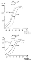
- Figures 2, 3 and 4 show the average luminance of the lamps tested, at different temperatures. Previously documented values for 20W, 40W and 65W lamps have also been shown, for comparison purposes.
- the inner surfaces of the outer glass tube or envelope of the inventive lamp may be coated with substances which will filter out undesired light.
- This technique enables critical ultraviolet lines to be further reduced with the aid of light-absorbing or fluorescent substances. The following substances have been found suitable in this respect.
- the substances are applied to the inner surface of the outer tube 8 in the form of a suspension having a dry solids content of between 0.3 and 0.5mg/cm2. These dyestuffs or pigmenting substances are burned onto the glass. Alternatively, organic dyestuffs may be used. When using organic dyestuff, however, burning, or stoving, cannot be effected at temperatures which lie above 500°C. In all events, a binder must be added when burning, baking,organic dyestuffs.
- One suitable binder in this regard is ammonium polymethyl acrylate.
Landscapes
- Vessels And Coating Films For Discharge Lamps (AREA)
- Gas Separation By Absorption (AREA)
- Secondary Cells (AREA)
- Crystals, And After-Treatments Of Crystals (AREA)
- Discharge Lamps And Accessories Thereof (AREA)
Claims (6)
- Niederdruckgasentladungslampe in Röhrenform zum Einsatz bei niedrigen Umgebungstemperaturen, welche eine innere Leuchtstoffröhre und eine äußere Glasröhre aufweist, welche die innere Röhre derart umgibt, daß ein rohrförmiger Zwischenraum dazwischen gebildet wird, wobei die äußere Röhre sich über die Elektroden der Lampe hinaus erstreckt und die Enden der Röhre mit den Enden der inneren Leuchtstoffröhre verbunden sind, und wobei die Enden der äußeren Glasröhre (8) in kreisförmigen Ausnehmungen aufgenommen sind, welche in Polymerringen (9) auf der inneren Leuchtstoffröhre (2) vorgesehen sind, dadurch gekennzeichnet, daß eine Siloxanverbindung in den Ausnehmungen und zwischen den Polymerringen (9) und der inneren Röhre (2) zur Herstellung einer hermetischen Verbindung zwischen der inneren und der äußeren Röhre und zur Erzielung einer trockenen Atmosphäre in dem rohrförmigen Raum (10) zwischen den Röhren vorgesehen ist, wobei sich die Siloxane beim Härten hydrolisieren und Polysiloxane bilden.
- Lampe nach Anspruch 1, dadurch gekennzeichnet, daß der rohrförmige Raum (10), welcher zwischen der inneren Leuchtstoffröhre (2) und der äußeren Glasröhre (8) gebildet wird, mit trockener, staubfreier Luft gefüllt ist.
- Lampe nach Anspruch 1 oder 2, dadurch gekennzeichnet, daß der rohrförmige Raum (10), welcher zwischen der inneren Leuchtstoffröhre (2) und der äußeren Glasröhre (8) gebildet wird, ein oder mehrere Edelgase enthält.
- Lampe nach Anspruch 3, dadurch gekennzeichnet, daß die innere Fläche der äußeren Glasröhre (8) ebenfalls mit einer Schicht aus einer fluoreszierenden Substanz überzogen ist.
- Lampe nach einem der vorangehenden Ansprüche, dadurch gekennzeichnet, daß die innere Fläche der äußeren Glasröhre (8) mit einer koherenten Schicht aus reflektierendem Material über einen Winkelbogen von bis zu 180° überzogen ist.
- Lampe nach einem der vorangehenden Ansprüche, dadurch gekennzeichnet, daß die gesamte innere Fläche der äußeren Glasröhre (8) oder ein Teil der Fläche mit einer oder mehreren Substanzen überzogen ist, welche die Farbe des durch die innere Leuchtstoffröhre (2) abgegebenen Lichts verändern.
Applications Claiming Priority (2)
| Application Number | Priority Date | Filing Date | Title |
|---|---|---|---|
| SE8800747 | 1988-03-02 | ||
| SE8800747A SE8800747D0 (sv) | 1988-03-02 | 1988-03-02 | Lagtrycks-gasurladdningslampa |
Publications (3)
| Publication Number | Publication Date |
|---|---|
| EP0331660A2 EP0331660A2 (de) | 1989-09-06 |
| EP0331660A3 EP0331660A3 (de) | 1991-01-23 |
| EP0331660B1 true EP0331660B1 (de) | 1995-06-28 |
Family
ID=20371561
Family Applications (2)
| Application Number | Title | Priority Date | Filing Date |
|---|---|---|---|
| EP88850215A Withdrawn EP0330808A1 (de) | 1988-03-02 | 1988-06-17 | Niederdruckgasentladungslampe |
| EP89850075A Expired - Lifetime EP0331660B1 (de) | 1988-03-02 | 1989-03-02 | Niederdruckgasentladungslampe |
Family Applications Before (1)
| Application Number | Title | Priority Date | Filing Date |
|---|---|---|---|
| EP88850215A Withdrawn EP0330808A1 (de) | 1988-03-02 | 1988-06-17 | Niederdruckgasentladungslampe |
Country Status (5)
| Country | Link |
|---|---|
| EP (2) | EP0330808A1 (de) |
| AT (1) | ATE124573T1 (de) |
| DE (1) | DE68923197T2 (de) |
| ES (1) | ES2073459T3 (de) |
| SE (2) | SE8800747D0 (de) |
Families Citing this family (13)
| Publication number | Priority date | Publication date | Assignee | Title |
|---|---|---|---|---|
| DE4215674A1 (de) * | 1992-05-13 | 1993-11-18 | Patent Treuhand Ges Fuer Elektrische Gluehlampen Mbh | Niederdruckentladungslampe |
| US5834889A (en) | 1995-09-22 | 1998-11-10 | Gl Displays, Inc. | Cold cathode fluorescent display |
| US6310436B1 (en) | 1995-09-22 | 2001-10-30 | Gl Displays, Inc. | Cold cathode fluorescent lamp and display |
| US6201352B1 (en) | 1995-09-22 | 2001-03-13 | Gl Displays, Inc. | Cold cathode fluorescent display |
| US6316872B1 (en) | 1995-09-22 | 2001-11-13 | Gl Displays, Inc. | Cold cathode fluorescent lamp |
| DE19737920A1 (de) * | 1997-08-27 | 1999-03-04 | Walter Dipl Chem Dr Rer N Tews | Niederdruck-Gasentladungslampe mit erhöhter Lebensdauer |
| JP2003520387A (ja) * | 1998-05-06 | 2003-07-02 | ジーエル ディスプレイズ インコーポレイテッド | 冷陰極螢光灯(ランプ)およびディスプレイ |
| DE19842795A1 (de) * | 1998-09-18 | 2000-03-23 | Patent Treuhand Ges Fuer Elektrische Gluehlampen Mbh | Leuchtstofflampe |
| AU7367100A (en) * | 1999-09-11 | 2001-04-17 | Gl Displays, Inc. | Gas discharge fluorescent device |
| US6515433B1 (en) | 1999-09-11 | 2003-02-04 | Coollite International Holding Limited | Gas discharge fluorescent device |
| SE0302595D0 (sv) * | 2003-09-30 | 2003-09-30 | Auralight Int Ab | Lysrör anpassat för kalla utrymmen |
| CN101375368B (zh) * | 2006-01-25 | 2010-11-03 | 皇家飞利浦电子股份有限公司 | Tld低压气体放电灯 |
| SE534541C2 (sv) * | 2009-09-16 | 2011-09-27 | Auralight Int Ab | Kompaktlysrör anpassat för kalla utrymmen försett med isolerande organ |
Family Cites Families (10)
| Publication number | Priority date | Publication date | Assignee | Title |
|---|---|---|---|---|
| US3179792A (en) * | 1962-09-06 | 1965-04-20 | Weiss Harry | Fluorescent lamp |
| US3358167A (en) * | 1965-10-18 | 1967-12-12 | Gen Electric | Jacketed discharge lamp |
| US3987331A (en) * | 1975-03-24 | 1976-10-19 | Gte Sylvania Incorporated | Ultraviolet emitting fluorescent lamp having internal reflector film |
| US4001628A (en) * | 1976-02-25 | 1977-01-04 | Westinghouse Electric Corporation | Low-pressure fluorescent discharge device which utilizes both inorganic and organic phosphors |
| US4131589A (en) * | 1976-12-13 | 1978-12-26 | General Electric Company | Low temperature transmission room temperature vulcanizable silicone compositions |
| NL7811350A (nl) * | 1978-11-17 | 1980-05-20 | Philips Nv | Lagedruknatriumdampontladingslamp. |
| US4221693A (en) * | 1979-03-02 | 1980-09-09 | Getson John C | Composition free of surface cure inhibition and method for preparing the same |
| JPS59128752A (ja) * | 1983-01-12 | 1984-07-24 | Karupu Kogyo Kk | 螢光灯エンドキヤツプ用樹脂組成物 |
| DD253702A1 (de) * | 1983-12-19 | 1988-01-27 | Adl Inst Gemueseproduktion | Gasentladungsstrahler fuer effektive strahlungsemission bei niedrigen umgebungstemperaturen |
| US4710679A (en) * | 1985-12-06 | 1987-12-01 | Gte Laboratories Incorporated | Fluorescent light source excited by excimer emission |
-
1988
- 1988-03-02 SE SE8800747A patent/SE8800747D0/xx unknown
- 1988-06-17 EP EP88850215A patent/EP0330808A1/de not_active Withdrawn
-
1989
- 1989-03-02 AT AT89850075T patent/ATE124573T1/de not_active IP Right Cessation
- 1989-03-02 ES ES89850075T patent/ES2073459T3/es not_active Expired - Lifetime
- 1989-03-02 EP EP89850075A patent/EP0331660B1/de not_active Expired - Lifetime
- 1989-03-02 DE DE68923197T patent/DE68923197T2/de not_active Expired - Lifetime
- 1989-03-02 SE SE8900728A patent/SE467279B/sv unknown
Also Published As
| Publication number | Publication date |
|---|---|
| ATE124573T1 (de) | 1995-07-15 |
| EP0330808A1 (de) | 1989-09-06 |
| SE8900728D0 (sv) | 1989-03-02 |
| DE68923197T2 (de) | 1995-11-09 |
| ES2073459T3 (es) | 1995-08-16 |
| SE8800747D0 (sv) | 1988-03-02 |
| SE467279B (sv) | 1992-06-22 |
| EP0331660A3 (de) | 1991-01-23 |
| DE68923197D1 (de) | 1995-08-03 |
| EP0331660A2 (de) | 1989-09-06 |
| SE8900728L (sv) | 1989-09-03 |
Similar Documents
| Publication | Publication Date | Title |
|---|---|---|
| EP0331660B1 (de) | Niederdruckgasentladungslampe | |
| JP2931819B2 (ja) | 硫黄又はセレンを有するランプ | |
| HUP9801470A2 (hu) | Kerámiabura, ezzel készült lámpa, valamint eljárás fémkerámia dugó előállítására | |
| CA2089543A1 (en) | Lighting apparatus | |
| KR960704340A (ko) | 포토광학용의 금속-할로겐화물 방전램프(metal-halide discharge lamp for photographic-lighting purposes) | |
| GB2067826A (en) | Metal vapour discharge lamp | |
| KR101445122B1 (ko) | 높은 색 온도를 가진 방전 램프 | |
| CA2179828A1 (en) | Incandescent halogen lamp | |
| WO1995019639A1 (en) | Metal halide lamp | |
| WO2003067628A3 (en) | Mercury-free high-pressure gas discharge lamp | |
| CA2196360A1 (en) | Electrodeless high intensity discharge lamp having a phosphorus fill | |
| CA2210591A1 (en) | Electrodeless high intensity discharge lamp with split lamp stem | |
| GB2054261A (en) | Metal halide high-intensity discharge lamps | |
| CA1181459A (en) | Metal vapor discharge lamp | |
| RU2028693C1 (ru) | Металлогалогенная лампа | |
| CN202282331U (zh) | 一种高强度节能气体放电灯 | |
| EP0204382B1 (de) | Hochdrucknatriumentladungslampe | |
| CN2319920Y (zh) | 应急灯用荧光灯管 | |
| RU169961U1 (ru) | Натриевая лампа | |
| SU760243A1 (en) | Method of sealling gas-discharge devices | |
| SU1737562A1 (ru) | Безртутна металлогалогенна лампа | |
| JPS57180064A (en) | Fluorescent lamp apparatus | |
| JPS63218145A (ja) | 高圧ナトリウムランプ | |
| EP1549113A4 (de) | Starter für eine fluoreszenzlampe und fluoreszenzlampe mit dem starter | |
| Van Vliet | Present-Day Light Sources |
Legal Events
| Date | Code | Title | Description |
|---|---|---|---|
| PUAI | Public reference made under article 153(3) epc to a published international application that has entered the european phase |
Free format text: ORIGINAL CODE: 0009012 |
|
| AK | Designated contracting states |
Kind code of ref document: A2 Designated state(s): AT BE DE ES FR GB IT NL SE |
|
| PUAL | Search report despatched |
Free format text: ORIGINAL CODE: 0009013 |
|
| AK | Designated contracting states |
Kind code of ref document: A3 Designated state(s): AT BE DE ES FR GB IT NL SE |
|
| 17P | Request for examination filed |
Effective date: 19910704 |
|
| 17Q | First examination report despatched |
Effective date: 19931111 |
|
| RAP1 | Party data changed (applicant data changed or rights of an application transferred) |
Owner name: AURALIGHT AKTIEBOLAG |
|
| GRAA | (expected) grant |
Free format text: ORIGINAL CODE: 0009210 |
|
| AK | Designated contracting states |
Kind code of ref document: B1 Designated state(s): AT BE DE ES FR GB IT NL SE |
|
| REF | Corresponds to: |
Ref document number: 124573 Country of ref document: AT Date of ref document: 19950715 Kind code of ref document: T |
|
| REF | Corresponds to: |
Ref document number: 68923197 Country of ref document: DE Date of ref document: 19950803 |
|
| ET | Fr: translation filed | ||
| REG | Reference to a national code |
Ref country code: ES Ref legal event code: FG2A Ref document number: 2073459 Country of ref document: ES Kind code of ref document: T3 |
|
| ITF | It: translation for a ep patent filed | ||
| PG25 | Lapsed in a contracting state [announced via postgrant information from national office to epo] |
Ref country code: SE Effective date: 19950928 |
|
| PLBE | No opposition filed within time limit |
Free format text: ORIGINAL CODE: 0009261 |
|
| STAA | Information on the status of an ep patent application or granted ep patent |
Free format text: STATUS: NO OPPOSITION FILED WITHIN TIME LIMIT |
|
| 26N | No opposition filed | ||
| REG | Reference to a national code |
Ref country code: GB Ref legal event code: IF02 |
|
| PG25 | Lapsed in a contracting state [announced via postgrant information from national office to epo] |
Ref country code: IT Free format text: LAPSE BECAUSE OF NON-PAYMENT OF DUE FEES Effective date: 20050302 |
|
| PGFP | Annual fee paid to national office [announced via postgrant information from national office to epo] |
Ref country code: ES Payment date: 20080328 Year of fee payment: 20 |
|
| PGRI | Patent reinstated in contracting state [announced from national office to epo] |
Ref country code: IT Effective date: 20080301 |
|
| PGFP | Annual fee paid to national office [announced via postgrant information from national office to epo] |
Ref country code: NL Payment date: 20080318 Year of fee payment: 20 Ref country code: GB Payment date: 20080320 Year of fee payment: 20 Ref country code: IT Payment date: 20080321 Year of fee payment: 20 |
|
| PGFP | Annual fee paid to national office [announced via postgrant information from national office to epo] |
Ref country code: AT Payment date: 20080314 Year of fee payment: 20 |
|
| PGFP | Annual fee paid to national office [announced via postgrant information from national office to epo] |
Ref country code: FR Payment date: 20080314 Year of fee payment: 20 Ref country code: DE Payment date: 20080321 Year of fee payment: 20 |
|
| PGFP | Annual fee paid to national office [announced via postgrant information from national office to epo] |
Ref country code: BE Payment date: 20080430 Year of fee payment: 20 |
|
| REG | Reference to a national code |
Ref country code: GB Ref legal event code: PE20 Expiry date: 20090301 |
|
| BE20 | Be: patent expired |
Owner name: *AURALIGHT A.B. Effective date: 20090302 |
|
| NLV7 | Nl: ceased due to reaching the maximum lifetime of a patent |
Effective date: 20090302 |
|
| REG | Reference to a national code |
Ref country code: ES Ref legal event code: FD2A Effective date: 20090303 |
|
| PG25 | Lapsed in a contracting state [announced via postgrant information from national office to epo] |
Ref country code: NL Free format text: LAPSE BECAUSE OF EXPIRATION OF PROTECTION Effective date: 20090302 |
|
| PG25 | Lapsed in a contracting state [announced via postgrant information from national office to epo] |
Ref country code: GB Free format text: LAPSE BECAUSE OF EXPIRATION OF PROTECTION Effective date: 20090301 |
|
| PG25 | Lapsed in a contracting state [announced via postgrant information from national office to epo] |
Ref country code: ES Free format text: LAPSE BECAUSE OF EXPIRATION OF PROTECTION Effective date: 20090303 |