EP0331602A2 - Tuyère pour capteur de vitesse angulaire - Google Patents
Tuyère pour capteur de vitesse angulaire Download PDFInfo
- Publication number
- EP0331602A2 EP0331602A2 EP89630021A EP89630021A EP0331602A2 EP 0331602 A2 EP0331602 A2 EP 0331602A2 EP 89630021 A EP89630021 A EP 89630021A EP 89630021 A EP89630021 A EP 89630021A EP 0331602 A2 EP0331602 A2 EP 0331602A2
- Authority
- EP
- European Patent Office
- Prior art keywords
- nozzle
- rate sensor
- sensor
- stream
- gas
- Prior art date
- Legal status (The legal status is an assumption and is not a legal conclusion. Google has not performed a legal analysis and makes no representation as to the accuracy of the status listed.)
- Granted
Links
- 230000035945 sensitivity Effects 0.000 claims abstract description 5
- 238000005086 pumping Methods 0.000 claims 1
- 239000012530 fluid Substances 0.000 description 14
- 239000007789 gas Substances 0.000 description 12
- 238000005259 measurement Methods 0.000 description 5
- 238000001816 cooling Methods 0.000 description 3
- 239000011324 bead Substances 0.000 description 2
- 230000010349 pulsation Effects 0.000 description 2
- 239000010935 stainless steel Substances 0.000 description 2
- 229910001220 stainless steel Inorganic materials 0.000 description 2
- 238000007792 addition Methods 0.000 description 1
- 238000005452 bending Methods 0.000 description 1
- 230000001419 dependent effect Effects 0.000 description 1
- 239000011521 glass Substances 0.000 description 1
- 239000011261 inert gas Substances 0.000 description 1
- 239000012212 insulator Substances 0.000 description 1
- 229910000833 kovar Inorganic materials 0.000 description 1
- 239000000463 material Substances 0.000 description 1
- 229910001092 metal group alloy Inorganic materials 0.000 description 1
- 230000010355 oscillation Effects 0.000 description 1
- 230000000087 stabilizing effect Effects 0.000 description 1
- WFKWXMTUELFFGS-UHFFFAOYSA-N tungsten Chemical compound [W] WFKWXMTUELFFGS-UHFFFAOYSA-N 0.000 description 1
- 229910052721 tungsten Inorganic materials 0.000 description 1
- 239000010937 tungsten Substances 0.000 description 1
Images

Classifications
-
- G—PHYSICS
- G01—MEASURING; TESTING
- G01C—MEASURING DISTANCES, LEVELS OR BEARINGS; SURVEYING; NAVIGATION; GYROSCOPIC INSTRUMENTS; PHOTOGRAMMETRY OR VIDEOGRAMMETRY
- G01C19/00—Gyroscopes; Turn-sensitive devices using vibrating masses; Turn-sensitive devices without moving masses; Measuring angular rate using gyroscopic effects
- G01C19/58—Turn-sensitive devices without moving masses
Definitions
- This invention relates to an angular rate sensor and more particularly to an angular rate sensor that incorporates a particularly shaped nozzle.
- fluidic angular rate sensors In fluidic angular rate sensors, a stream of a suitable fluid, such as an inert gas, is pressurized and passed through a nozzle. The stream of fluid is directed by the nozzle toward a pair of temperature sensitive resistive elements which are differentially cooled by the stream whenever the stream is diverted (such as by Coriolis forces that are encountered during angular rotation of the sensor). The differential cooling provides a measurable differential signal across the resistive elements which is proportional to the angular rate of turn of the sensor.
- Such fluidic rate sensors are generally accurate in a plane of sensitivity which is generally defined as being perpendicular to the plane in which the resistive elements lie. Fluidic angular rate sensors are typified by those disclosed in U.S. Patents 3,587,328, to Schuemann, 3,626,765 to Moore, and 4,020,700 to Lopiccolo et al.
- Such prior art angular rate sensors utilize a nozzle having a circular opening.
- the circular opening provides a laminar gas stream having a parabolic velocity profile.
- the shape of the velocity profile of the gas stream is defined as a function of the distance from the center of the opening.
- the gas stream moves more quickly at its center and moves more slowly near its sides thereby defining the parabolic shape of the profile.
- a portion of each leg of the profile is roughly linear. Each linear portion impinges upon one of the resistive elements throughout the normal operating range of the rate sensor. If the portions of the profile that impinge upon the resistive elements are nonlinear, measurement of the differential cooling of the elements may not provide an accurate measurement of the angular rate of turn of the sensor.
- an angular rate sensor having a nozzle which shapes the velocity profile of a gas stream passing therethrough so that a linear portion of the profile impinges upon the resistive elements of the sensor even when high angular rates of turn are encountered.
- the nozzle is generally rectangularly shaped having a pair of parallel sides arranged perpendicularly to the resistive elements of the sensor and a pair of connecting sides.
- the connecting sides are semi-circularly shaped.
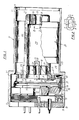
- the senor includes a cylindrically shaped nozzle block 20 having two overall diameters associated with two different internal diameters of the casing resulting from the shoulder 13.
- the nozzle block 20 has a major annular groove 23 which, with the case, forms a fluid manifold chamber 24 for receiving fluid under pressure from a feed port 25 formed in the wall of the groove 23.
- the nozzle block also includes; fluid feed tubes 26 which conduct the pressurized gas stream from the feed manifold chamber to an inlet manifold chamber 27 formed between the nozzle block and the end cover 16, and a nozzle 28 (as will be discussed infra) disposed in the end wall of the nozzle block to provide a fluid conduit from the manifold chamber 27 into a jet chamber 29 formed as a major axial bore within the block.
- the nozzle block also has a pump mounting flange 37 including an internal counter bore 38, a wire feed through hole 39, and a plurality of mill slots (such as the slot 40) which may be used either for wire passageways or as a key for aligning the nozzle block within the casing.
- the nozzle block is constructed of a nonmagnetic, anti-corrosive ,aterial, such as 300 series stainless steel.
- the nozzle block further includes a counter bore 45 for seating a sensor plug assembly 50 in alignment with the nozzle in the jet chamber 29.
- the plug assembly includes exhaust ports 51 to permit the fluid flow through the plug into an exhaust chamber 52 formed in the pump mounting flange 37.
- the sensing elements which are preferably tungsten wires 53, 54, are mounted to associated pairs of Kovar ⁇ metal alloy posts (56, 57 for the element 53). The posts are secured in the plug through glass insulators 60 and the sensor elements are connected through insulated wires 61 (and posts 62) which may be routed through the milled slot 40 to the access end of the casing.
- the impulse pump assembly 70 includes a piezoelectric diaphragm 71 with a pump orifice 72.
- the diaphragm is metallurgically bonded to a mounting rim 73 of a flexible, cylindrical support flexure 74.
- the flexure has an oppositely directed support rim 75 at the other end which seats in the counter bore 38 of the nozzle block.
- the application of AC voltage to the piezoelectric diaphragm causes the diaphragm to oscillate, producing fluid pressure pulsations in the pump chamber 76 formed internally of the flexure 74. These pulsations force fluid under pressure through the pump orifice 72, creating a fluid pressure concentration in the exhaust chamber 52.
- the exhaust chamber in turn forces the fluid through the feed port 25, the manifold 24, and the feed tubes 26 to the inlet manifold chamber 27 which supplies the nozzle 28.
- the flow rate of the fluid in cubic feet per minute (CFM) is dependent on the geometry of the pump chamber, the pump diaphragm, and the frequency of oscillation of the pump.
- the fluid pressure at the plenum chamber is typically about 0.0005 p.s.i. which will maintain a gas stream velocity of about 100 inches per second and a flow rate of less than 2 cubic feet per hour.
- the Reynolds number of the gas stream at the nozzle is between 400 and 1,000 to provide a laminar flow from the nozzle.
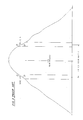
- the nozzle opening has a pair of parallel sides 77 being spaced a distance a apart of about 0.060 to 0.064 inches and a pair of connecting portions 79 being spaced a distance b apart of about 0.122 to 0.126 inches.
- the connecting portions may be semicircularly shaped to reduce turbulence around the sides of the bore thereby stabilizing the velocity profile of the gas flow.
- the input end 81 (see fig. 1) of the nozzle is faired along a radius 83 of about 0.065 to 0.075 inches to help achieve a laminar flow velocity profile of the gas stream exiting the nozzle.
- the output end of the nozzle is placed perpendicularly about 0.204 inches from the sensing elements. Each sensing element aligns with the end portions of the connecting portions (see phantom lines 85 which indicate the positions of the sensing elements 53,54).
- the shape of the nozzle creates a velocity profile (see Fig. 4) within the gas stream impinging upon the sensing elements.
- the velocity profile has a pair of relatively large, substantially linear (i.e. below 1% deviation from linearity) portions 87 along the sides of the profile. Each portion 87 is centered about one of the sensing elements.
- Fig. 3 shows the velocity profile provided by a prior art circular nozzle.
- the prior art profile has a pair of substantially linear portions 89 that are much smaller than the portions 87. Because of the larger areas of linearity provided by the roughly rectangularly shaped nozzle of this invention, larger bending moments of the gas stream caused by rapid angular motion (i.e.
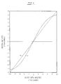
- Fig. 5 demonstrates the linearity of response relating to the linearity of the output of the sensing elements.
- a change in the angular rate of turn gives a demonstrably linear response of the cooling of the sensing elements (see curve a).
- the response of the standard circular nozzle is decidedly nonlinear (see curve b) and therefore subject to inaccurate differential velocity across the sensing elements which lead to inaccurate measurements of angular rate of turn.
Landscapes
- Physics & Mathematics (AREA)
- Engineering & Computer Science (AREA)
- General Physics & Mathematics (AREA)
- Radar, Positioning & Navigation (AREA)
- Remote Sensing (AREA)
- Measuring Volume Flow (AREA)
- Investigating Or Analyzing Materials By The Use Of Electric Means (AREA)
- Measuring Temperature Or Quantity Of Heat (AREA)
- Indicating Or Recording The Presence, Absence, Or Direction Of Movement (AREA)
Applications Claiming Priority (2)
| Application Number | Priority Date | Filing Date | Title |
|---|---|---|---|
| US07/151,762 US4856332A (en) | 1988-02-03 | 1988-02-03 | Angular rate sensor nozzle |
| US151762 | 1988-02-03 |
Publications (3)
| Publication Number | Publication Date |
|---|---|
| EP0331602A2 true EP0331602A2 (fr) | 1989-09-06 |
| EP0331602A3 EP0331602A3 (fr) | 1992-03-18 |
| EP0331602B1 EP0331602B1 (fr) | 1994-05-04 |
Family
ID=22540145
Family Applications (1)
| Application Number | Title | Priority Date | Filing Date |
|---|---|---|---|
| EP89630021A Expired - Lifetime EP0331602B1 (fr) | 1988-02-03 | 1989-02-02 | Tuyère pour capteur de vitesse angulaire |
Country Status (4)
| Country | Link |
|---|---|
| US (1) | US4856332A (fr) |
| EP (1) | EP0331602B1 (fr) |
| JP (1) | JPH01316665A (fr) |
| DE (2) | DE331602T1 (fr) |
Family Cites Families (4)
| Publication number | Priority date | Publication date | Assignee | Title |
|---|---|---|---|---|
| US3205715A (en) * | 1962-04-18 | 1965-09-14 | James M Meek | Angular rate sensor utilizing at least one fluid beam |
| NL297933A (fr) * | 1962-09-21 | |||
| US3626765A (en) * | 1969-06-05 | 1971-12-14 | Hercules Inc | Fluid jet deflection type instrument |
| US4594894A (en) * | 1984-09-04 | 1986-06-17 | United Technologies Corporation | Angular velocity sensor |
-
1988
- 1988-02-03 US US07/151,762 patent/US4856332A/en not_active Expired - Fee Related
-
1989
- 1989-02-02 DE DE198989630021T patent/DE331602T1/de active Pending
- 1989-02-02 DE DE68915036T patent/DE68915036T2/de not_active Expired - Fee Related
- 1989-02-02 EP EP89630021A patent/EP0331602B1/fr not_active Expired - Lifetime
- 1989-02-03 JP JP1026521A patent/JPH01316665A/ja active Pending
Also Published As
| Publication number | Publication date |
|---|---|
| DE331602T1 (de) | 1989-12-07 |
| US4856332A (en) | 1989-08-15 |
| DE68915036T2 (de) | 1994-08-18 |
| JPH01316665A (ja) | 1989-12-21 |
| EP0331602A3 (fr) | 1992-03-18 |
| DE68915036D1 (de) | 1994-06-09 |
| EP0331602B1 (fr) | 1994-05-04 |
Similar Documents
| Publication | Publication Date | Title |
|---|---|---|
| Liepmann et al. | Investigations of free turbulent mixing | |
| EP2372315B1 (fr) | Débitmètre à vortex doté d'une plaque de détection d'oscillations de vortex | |
| US5447073A (en) | Multimeasurement replaceable vortex sensor | |
| EP1735598B1 (fr) | Capteur de pression capacitif annulaire | |
| US4696194A (en) | Fluid flow measurement | |
| US4046010A (en) | Pressure transducer with welded tantalum diaphragm | |
| EP0255056A2 (fr) | Procédé de mesure de la vitesse d'écoulement d'un gaz | |
| US8590388B2 (en) | Ultra-miniature multi-hole probes having high frequency, high temperature responses | |
| JPH0789122B2 (ja) | 空間内の自由な流れの流速を測定する装置と方法 | |
| US4020700A (en) | Unitary fluidic angular rate sensor | |
| US6041659A (en) | Methods and apparatus for sensing differential and gauge static pressure in a fluid flow line | |
| JPH0863235A (ja) | 差圧式質量流量コントロール装置 | |
| EP0156855B1 (fr) | Dispositif de mesure a tourbillons de petite dimension de ligne | |
| JPS6141923A (ja) | 流量計 | |
| US3333468A (en) | Mass flow measuring system | |
| US6732596B2 (en) | Critical gas flow measurement apparatus and method | |
| US3326041A (en) | Apparatus for developing differential pressures in a conduit line | |
| US4856332A (en) | Angular rate sensor nozzle | |
| EP3974782B1 (fr) | Ensemble capteur pour mesurer la vitesse moyenne dans des conduites ou des canaux ouverts | |
| EP0037795A2 (fr) | Capteur de la vitesse angulaire comportant une pompe à impulsion à membrane symétrique | |
| US3319471A (en) | Pickoff means for fluid vortex rate sensor | |
| JPH01299416A (ja) | 流量変換装置 | |
| JP2929731B2 (ja) | カルマン渦流量計及びその製造方法 | |
| JPH05322619A (ja) | 流体搬送装置 | |
| JPH01207634A (ja) | 差圧形流量計 |
Legal Events
| Date | Code | Title | Description |
|---|---|---|---|
| PUAI | Public reference made under article 153(3) epc to a published international application that has entered the european phase |
Free format text: ORIGINAL CODE: 0009012 |
|
| AK | Designated contracting states |
Kind code of ref document: A2 Designated state(s): DE FR GB IT |
|
| ITCL | It: translation for ep claims filed |
Representative=s name: RICCARDI SERGIO & CO. |
|
| EL | Fr: translation of claims filed | ||
| DET | De: translation of patent claims | ||
| PUAL | Search report despatched |
Free format text: ORIGINAL CODE: 0009013 |
|
| AK | Designated contracting states |
Kind code of ref document: A3 Designated state(s): DE FR GB IT |
|
| 17P | Request for examination filed |
Effective date: 19920416 |
|
| 17Q | First examination report despatched |
Effective date: 19921214 |
|
| GRAA | (expected) grant |
Free format text: ORIGINAL CODE: 0009210 |
|
| AK | Designated contracting states |
Kind code of ref document: B1 Designated state(s): DE FR GB IT |
|
| ET | Fr: translation filed | ||
| REF | Corresponds to: |
Ref document number: 68915036 Country of ref document: DE Date of ref document: 19940609 |
|
| ITF | It: translation for a ep patent filed | ||
| PGFP | Annual fee paid to national office [announced via postgrant information from national office to epo] |
Ref country code: FR Payment date: 19950113 Year of fee payment: 7 |
|
| PGFP | Annual fee paid to national office [announced via postgrant information from national office to epo] |
Ref country code: GB Payment date: 19950119 Year of fee payment: 7 Ref country code: DE Payment date: 19950119 Year of fee payment: 7 |
|
| PLBE | No opposition filed within time limit |
Free format text: ORIGINAL CODE: 0009261 |
|
| STAA | Information on the status of an ep patent application or granted ep patent |
Free format text: STATUS: NO OPPOSITION FILED WITHIN TIME LIMIT |
|
| 26N | No opposition filed | ||
| PG25 | Lapsed in a contracting state [announced via postgrant information from national office to epo] |
Ref country code: GB Effective date: 19960202 |
|
| GBPC | Gb: european patent ceased through non-payment of renewal fee |
Effective date: 19960202 |
|
| PG25 | Lapsed in a contracting state [announced via postgrant information from national office to epo] |
Ref country code: FR Effective date: 19961031 |
|
| PG25 | Lapsed in a contracting state [announced via postgrant information from national office to epo] |
Ref country code: DE Effective date: 19961101 |
|
| REG | Reference to a national code |
Ref country code: FR Ref legal event code: ST |
|
| PG25 | Lapsed in a contracting state [announced via postgrant information from national office to epo] |
Ref country code: IT Free format text: LAPSE BECAUSE OF NON-PAYMENT OF DUE FEES;WARNING: LAPSES OF ITALIAN PATENTS WITH EFFECTIVE DATE BEFORE 2007 MAY HAVE OCCURRED AT ANY TIME BEFORE 2007. THE CORRECT EFFECTIVE DATE MAY BE DIFFERENT FROM THE ONE RECORDED. Effective date: 20050202 |