EP0331013A2 - Tool for removing the remaining plastic from the gate of an injection mold - Google Patents
Tool for removing the remaining plastic from the gate of an injection mold Download PDFInfo
- Publication number
- EP0331013A2 EP0331013A2 EP89103184A EP89103184A EP0331013A2 EP 0331013 A2 EP0331013 A2 EP 0331013A2 EP 89103184 A EP89103184 A EP 89103184A EP 89103184 A EP89103184 A EP 89103184A EP 0331013 A2 EP0331013 A2 EP 0331013A2
- Authority
- EP
- European Patent Office
- Prior art keywords
- tapered end
- injection mold
- shank
- gate
- worn
- Prior art date
- Legal status (The legal status is an assumption and is not a legal conclusion. Google has not performed a legal analysis and makes no representation as to the accuracy of the status listed.)
- Granted
Links
- 238000002347 injection Methods 0.000 title claims abstract description 28
- 239000007924 injection Substances 0.000 title claims abstract description 28
- XEEYBQQBJWHFJM-UHFFFAOYSA-N Iron Chemical compound [Fe] XEEYBQQBJWHFJM-UHFFFAOYSA-N 0.000 claims abstract description 16
- 239000002184 metal Substances 0.000 claims abstract description 9
- 229910052751 metal Inorganic materials 0.000 claims abstract description 9
- 229910052742 iron Inorganic materials 0.000 claims abstract description 8
- 229910001369 Brass Inorganic materials 0.000 claims description 8
- 239000010951 brass Substances 0.000 claims description 8
- RYGMFSIKBFXOCR-UHFFFAOYSA-N Copper Chemical compound [Cu] RYGMFSIKBFXOCR-UHFFFAOYSA-N 0.000 claims description 2
- 229910000831 Steel Inorganic materials 0.000 claims description 2
- 229910052802 copper Inorganic materials 0.000 claims description 2
- 239000010949 copper Substances 0.000 claims description 2
- 239000010959 steel Substances 0.000 claims description 2
- 238000000465 moulding Methods 0.000 abstract description 5
- 230000000694 effects Effects 0.000 abstract description 3
- 238000011109 contamination Methods 0.000 abstract description 2
- 238000004519 manufacturing process Methods 0.000 abstract description 2
- 239000000463 material Substances 0.000 description 4
- 230000002411 adverse Effects 0.000 description 1
- 229910052782 aluminium Inorganic materials 0.000 description 1
- XAGFODPZIPBFFR-UHFFFAOYSA-N aluminium Chemical compound [Al] XAGFODPZIPBFFR-UHFFFAOYSA-N 0.000 description 1
- 238000005452 bending Methods 0.000 description 1
- 230000004048 modification Effects 0.000 description 1
- 238000012986 modification Methods 0.000 description 1
- 238000010137 moulding (plastic) Methods 0.000 description 1
- 239000000843 powder Substances 0.000 description 1
- 238000005096 rolling process Methods 0.000 description 1
Images
Classifications
-
- B—PERFORMING OPERATIONS; TRANSPORTING
- B25—HAND TOOLS; PORTABLE POWER-DRIVEN TOOLS; MANIPULATORS
- B25D—PERCUSSIVE TOOLS
- B25D3/00—Hand chisels
-
- B—PERFORMING OPERATIONS; TRANSPORTING
- B29—WORKING OF PLASTICS; WORKING OF SUBSTANCES IN A PLASTIC STATE IN GENERAL
- B29C—SHAPING OR JOINING OF PLASTICS; SHAPING OF MATERIAL IN A PLASTIC STATE, NOT OTHERWISE PROVIDED FOR; AFTER-TREATMENT OF THE SHAPED PRODUCTS, e.g. REPAIRING
- B29C45/00—Injection moulding, i.e. forcing the required volume of moulding material through a nozzle into a closed mould; Apparatus therefor
- B29C45/17—Component parts, details or accessories; Auxiliary operations
- B29C45/1759—Removing sprues from sprue-channels
Definitions
- the present invention relates to a tool for removing the remaining plastic from the gate of an injection mold, which tool is called “injection mold gate cleaner” hereinafter and in the claims.
- a plastic material is poured into an injection mold, and then the material is left in the gate of the injection mold to close the gate when it becomes hard. The remaining hardened plastic must be removed from the gate of the injection mold before pouring the melted material. Then, an injection mold gate cleaner is used.
- a conventional injection mold gate cleaner is a brass rod having a conical tip.
- the conical tip of the rod is inserted in the gate of the injection mold, and the rear end of the rod is struck by a hammer to remove the remaining plastic from the gate of the injection mold.
- Brass is less harder than the material of the injection mold, and therefore there is no fear of causing damage to the gate of the injection mold.
- the tip end of the rod will be worn and rounded. As a result the tip end of the rod cannot be inserted deep in the gate of the injection mold, and therefore the remaining plastic cannot be removed completely.
- the tapered brass rod must be ground and sharpened every time its tip is worn and rounded. This, however, is tedious and time-consuming work. Still disadvantageously, brass powder is produced while the brass rod is ground, and sometimes such pulverized brass is put in a plastic molding machine. This causes an adverse effect on the quality of precision molds.
- One object of the present invention is to provide an injection mold gate cleaner requiring no grinding.
- Another object of the present invention is to provide an injection mold gate cleaner making it possible to improve the molding efficiency.
- an injection mold gate cleaner comprises a disposable tapered end of a metal which is less hard than iron, and a shank to which said disposable tapered end is detachably fixed.
- the tapered end may have a conical shape, and the shank may have a polygonal shape in cross section.
- the tapered end of the rod is inserted in the gate of the injection mold, and the rear end of the rod is struck by a hammer to remove the remaining plastic from the gate of the injection mold.
- the tip end of the rod is worn and rounded, it is removed from the shank, and a new tapered end is attached to the shank. Replacement of a worn tapered end by a new one makes it unnecessary to grind the worn tapered end.
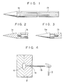
- Fig.1 shows an injection mold gate cleaner according to a first embodiment of the present invention as comprising a disposable tapered end 1a of a metal which is less hard than iron, such as brass, copper or aluminum, and an iron shank 1b to which the disposable tapered end 1a is detachably fixed.
- the injection mold is made of iron.
- the tapered end 1a and the shank 1b are detachably connected to each other by screwing the male-tapped projection of the shank (or the taperd end) to the female-tapped recess of the tapered end (or the shank).
- the shank and the portion of the tapered end excluding the conical tip are made in the form of polygon, thereby preventing the tool from rolling when put on a flat top.
- a worker holds the shank 1b of the tool in hand, and he puts the cylindrical tip of the tapered end 1a is inserted in the gate of the mold 2 to strike the rear end of the shank with a hammer 3, therby removing the remaining plastic from the gate of the mold (See Fig.4).
- the cavity of the mold 2 is indicated at 4.
- the tapered end 1a is worn, it is unscrewed and removed from the shank 1b, and then a new tapered end is screwed and fixed to the shank 1b.
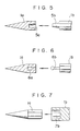
- Figs.5 to 7 show modifications of joint to integrally connect a tapered end to an associated shank.
- Fig.5 shows a joint comprising a tapered recess 5a formed on the rear end of the tapered end 1a and a tapered projection 5b integrally connected to the front end of the shank 1b.
- Fig 6 shows another joint comprising a long round-and- spherical recess 6a made on the rear end of the tapered end 1a and a long round-and-spherical projection 6b integrally connected to the front end of the shank 1b.
- Fig.7 shows still another joint comprising a polygonal recess 7b made on the front end of the shank 1b to permit the polygonal portion of the tapered end 1a to fit in the polygonal recess 7b of the shank lb.
- the shank 1b must be larger across than the tapered end 1a.
- Figs.5 and 7 are simple and easy to be made whereas the joint of Fig.6 permits rigid connection between the tapered end and the shank.
- the male and female joint portions of Figs.5 to 7 may be provided to the tapered end and the shank in the opposite way to what are shown in Figs.5 to 7.
- the replacement of a worn-out part by a new one makes it unnecessary to grind and reshape the worn-out part, accordingly improving the efficiency with which a series of moldings are carried out in succession.
- Production of no pulverized metal eliminates a cause for contamination of molding machines and ill effect on the quality of precision molds.
- the shank is made of a hard metal such as iron or steel, and. the tapered end is made of a soft metal. Therefore, a worker can hammer the tool with strong force without fear of bending the shank and damaging the mold.
Landscapes
- Engineering & Computer Science (AREA)
- Mechanical Engineering (AREA)
- Manufacturing & Machinery (AREA)
- Moulds For Moulding Plastics Or The Like (AREA)
- Injection Moulding Of Plastics Or The Like (AREA)
Abstract
Description
- The present invention relates to a tool for removing the remaining plastic from the gate of an injection mold, which tool is called "injection mold gate cleaner" hereinafter and in the claims.
- As is well known, a plastic material is poured into an injection mold, and then the material is left in the gate of the injection mold to close the gate when it becomes hard. The remaining hardened plastic must be removed from the gate of the injection mold before pouring the melted material. Then, an injection mold gate cleaner is used.
- A conventional injection mold gate cleaner is a brass rod having a conical tip. In use the conical tip of the rod is inserted in the gate of the injection mold, and the rear end of the rod is struck by a hammer to remove the remaining plastic from the gate of the injection mold. Brass is less harder than the material of the injection mold, and therefore there is no fear of causing damage to the gate of the injection mold. The tip end of the rod, however, will be worn and rounded. As a result the tip end of the rod cannot be inserted deep in the gate of the injection mold, and therefore the remaining plastic cannot be removed completely.
- The tapered brass rod must be ground and sharpened every time its tip is worn and rounded. This, however, is tedious and time-consuming work. Still disadvantageously, brass powder is produced while the brass rod is ground, and sometimes such pulverized brass is put in a plastic molding machine. This causes an adverse effect on the quality of precision molds.
- One object of the present invention is to provide an injection mold gate cleaner requiring no grinding.
- Another object of the present invention is to provide an injection mold gate cleaner making it possible to improve the molding efficiency.
- To attain these objects an injection mold gate cleaner according to the present invention comprises a disposable tapered end of a metal which is less hard than iron, and a shank to which said disposable tapered end is detachably fixed. The tapered end may have a conical shape, and the shank may have a polygonal shape in cross section. In use the tapered end of the rod is inserted in the gate of the injection mold, and the rear end of the rod is struck by a hammer to remove the remaining plastic from the gate of the injection mold. When the tip end of the rod is worn and rounded, it is removed from the shank, and a new tapered end is attached to the shank. Replacement of a worn tapered end by a new one makes it unnecessary to grind the worn tapered end.
- Other advantages of the present invention will be understood from the following description of injection mold gate cleaners according to preferred embodiments of the present invention, which are shown in the accompanying drawings:
- Fig.1 is a side view of an injection mold gate cleaner according to a first embodiment of the present invention;
- Figs.2 and 3 are longitudinal sections of different tapered ends;
- Fig.4 shows how the injection mold gate cleaner is used to remove the remaining plastic from the gate of the injection mold; and
- Figs.5 to 7 are longitudinal sections of different tapered end.
- Fig.1 shows an injection mold gate cleaner according to a first embodiment of the present invention as comprising a disposable tapered end 1a of a metal which is less hard than iron, such as brass, copper or aluminum, and an iron shank 1b to which the disposable tapered end 1a is detachably fixed. The injection mold is made of iron. As shown in Fig.2 or 3, the tapered end 1a and the shank 1b are detachably connected to each other by screwing the male-tapped projection of the shank (or the taperd end) to the female-tapped recess of the tapered end (or the shank). The shank and the portion of the tapered end excluding the conical tip are made in the form of polygon, thereby preventing the tool from rolling when put on a flat top. In use a worker holds the shank 1b of the tool in hand, and he puts the cylindrical tip of the tapered end 1a is inserted in the gate of the
mold 2 to strike the rear end of the shank with a hammer 3, therby removing the remaining plastic from the gate of the mold (See Fig.4). The cavity of themold 2 is indicated at 4. When the tapered end 1a is worn, it is unscrewed and removed from the shank 1b, and then a new tapered end is screwed and fixed to the shank 1b. Figs.5 to 7 show modifications of joint to integrally connect a tapered end to an associated shank. - Fig.5 shows a joint comprising a
tapered recess 5a formed on the rear end of the tapered end 1a and atapered projection 5b integrally connected to the front end of the shank 1b. Fig 6 shows another joint comprising a long round-and-spherical recess 6a made on the rear end of the tapered end 1a and a long round-and-spherical projection 6b integrally connected to the front end of the shank 1b. - Fig.7 shows still another joint comprising a
polygonal recess 7b made on the front end of the shank 1b to permit the polygonal portion of the tapered end 1a to fit in thepolygonal recess 7b of the shank lb. In this case the shank 1b must be larger across than the tapered end 1a. - The joints of Figs.5 and 7 are simple and easy to be made whereas the joint of Fig.6 permits rigid connection between the tapered end and the shank. As is the case with Figs.2 and 3, the male and female joint portions of Figs.5 to 7 may be provided to the tapered end and the shank in the opposite way to what are shown in Figs.5 to 7.
- As may be understood from the above, the replacement of a worn-out part by a new one makes it unnecessary to grind and reshape the worn-out part, accordingly improving the efficiency with which a series of moldings are carried out in succession. Production of no pulverized metal eliminates a cause for contamination of molding machines and ill effect on the quality of precision molds. The shank is made of a hard metal such as iron or steel, and. the tapered end is made of a soft metal. Therefore, a worker can hammer the tool with strong force without fear of bending the shank and damaging the mold.
Claims (3)
Applications Claiming Priority (2)
| Application Number | Priority Date | Filing Date | Title |
|---|---|---|---|
| JP2641188U JPH0536655Y2 (en) | 1988-02-29 | 1988-02-29 | |
| JP26411/88U | 1988-02-29 |
Publications (3)
| Publication Number | Publication Date |
|---|---|
| EP0331013A2 true EP0331013A2 (en) | 1989-09-06 |
| EP0331013A3 EP0331013A3 (en) | 1991-05-08 |
| EP0331013B1 EP0331013B1 (en) | 1994-01-05 |
Family
ID=12192809
Family Applications (1)
| Application Number | Title | Priority Date | Filing Date |
|---|---|---|---|
| EP19890103184 Expired - Lifetime EP0331013B1 (en) | 1988-02-29 | 1989-02-23 | Tool for removing the remaining plastic from the gate of an injection mold |
Country Status (3)
| Country | Link |
|---|---|
| EP (1) | EP0331013B1 (en) |
| JP (1) | JPH0536655Y2 (en) |
| DE (1) | DE68911956T2 (en) |
Cited By (2)
| Publication number | Priority date | Publication date | Assignee | Title |
|---|---|---|---|---|
| TWI399278B (en) * | 2008-08-08 | 2013-06-21 | Hon Hai Prec Ind Co Ltd | Removing device |
| CN112519123A (en) * | 2020-11-16 | 2021-03-19 | 湖南京能新能源科技有限公司 | Charging pile intelligent production line process flow and method |
Families Citing this family (1)
| Publication number | Priority date | Publication date | Assignee | Title |
|---|---|---|---|---|
| JP6087859B2 (en) * | 2014-03-27 | 2017-03-01 | Towa株式会社 | Resin molding apparatus and resin molding method |
Family Cites Families (4)
| Publication number | Priority date | Publication date | Assignee | Title |
|---|---|---|---|---|
| GB224046A (en) * | 1923-09-20 | 1924-11-06 | Gibson Stables | Improvements in or relating to chisels and like tools |
| FR1168010A (en) * | 1956-11-21 | 1958-12-03 | Improvement in automatic injection presses, of the barrel type | |
| CH428195A (en) * | 1965-07-05 | 1967-01-15 | Bucher Guyer Ag Masch | Injection unit for injection molding machines |
| FR2570014A1 (en) * | 1984-09-11 | 1986-03-14 | Stephanoises Forges | Mason's spike with a removable end |
-
1988
- 1988-02-29 JP JP2641188U patent/JPH0536655Y2/ja not_active Expired - Lifetime
-
1989
- 1989-02-23 DE DE1989611956 patent/DE68911956T2/en not_active Expired - Fee Related
- 1989-02-23 EP EP19890103184 patent/EP0331013B1/en not_active Expired - Lifetime
Cited By (3)
| Publication number | Priority date | Publication date | Assignee | Title |
|---|---|---|---|---|
| TWI399278B (en) * | 2008-08-08 | 2013-06-21 | Hon Hai Prec Ind Co Ltd | Removing device |
| CN112519123A (en) * | 2020-11-16 | 2021-03-19 | 湖南京能新能源科技有限公司 | Charging pile intelligent production line process flow and method |
| CN112519123B (en) * | 2020-11-16 | 2023-01-17 | 湖南京能新能源科技有限公司 | A charging pile intelligent production line process and method |
Also Published As
| Publication number | Publication date |
|---|---|
| EP0331013A3 (en) | 1991-05-08 |
| DE68911956D1 (en) | 1994-02-17 |
| JPH01132718U (en) | 1989-09-08 |
| JPH0536655Y2 (en) | 1993-09-16 |
| EP0331013B1 (en) | 1994-01-05 |
| DE68911956T2 (en) | 1994-07-21 |
Similar Documents
| Publication | Publication Date | Title |
|---|---|---|
| EP0010074B1 (en) | Cutting tool | |
| KR100563626B1 (en) | Screw and combination of it and screwdriver bits | |
| US5362185A (en) | Device for positioning components | |
| US4926537A (en) | Tie rod and ball joint separator | |
| JPH04294910A (en) | Inserting tip for peeling working and cutting tool | |
| EP0331013B1 (en) | Tool for removing the remaining plastic from the gate of an injection mold | |
| US6340274B1 (en) | Interference fit type cutting tool | |
| JPH06171294A (en) | Tool for engraving machine | |
| EP1203639B1 (en) | Hand tool for stripping material | |
| JPS5866613A (en) | Hand tool for cutting material of workpiece, particularly,for cutting or crushing corner of workpiece | |
| GB1586983A (en) | Chisel | |
| US2421926A (en) | Jewel carrying tool and method of making the same | |
| KR20000048027A (en) | Interference fit type cutting tool | |
| US2351250A (en) | Battery service tool | |
| JP2529997Y2 (en) | Replaceable blade type only | |
| GB2135625A (en) | Tool handle | |
| CN218542880U (en) | Precision part based on hot cutting processing | |
| KR200256578Y1 (en) | Handle structure of chisel type tools | |
| JPS597473Y2 (en) | Rebar joint tightening tool | |
| EP4008460A1 (en) | Precision thermal modular toolholder | |
| JPH0373280A (en) | Chisel and holder for fitting thereof | |
| KR950005320Y1 (en) | Improvement core of pipe coupler casting | |
| JPS5926760B2 (en) | drilling teeth | |
| JPH11197917A (en) | Replaceable soft jaw for chuck | |
| EP0055998A1 (en) | Tool element |
Legal Events
| Date | Code | Title | Description |
|---|---|---|---|
| PUAI | Public reference made under article 153(3) epc to a published international application that has entered the european phase |
Free format text: ORIGINAL CODE: 0009012 |
|
| AK | Designated contracting states |
Kind code of ref document: A2 Designated state(s): DE GB IT |
|
| PUAL | Search report despatched |
Free format text: ORIGINAL CODE: 0009013 |
|
| AK | Designated contracting states |
Kind code of ref document: A3 Designated state(s): DE GB IT |
|
| 17P | Request for examination filed |
Effective date: 19910618 |
|
| 17Q | First examination report despatched |
Effective date: 19930402 |
|
| GRAA | (expected) grant |
Free format text: ORIGINAL CODE: 0009210 |
|
| AK | Designated contracting states |
Kind code of ref document: B1 Designated state(s): DE GB IT |
|
| REF | Corresponds to: |
Ref document number: 68911956 Country of ref document: DE Date of ref document: 19940217 |
|
| ITF | It: translation for a ep patent filed | ||
| PLBE | No opposition filed within time limit |
Free format text: ORIGINAL CODE: 0009261 |
|
| STAA | Information on the status of an ep patent application or granted ep patent |
Free format text: STATUS: NO OPPOSITION FILED WITHIN TIME LIMIT |
|
| 26N | No opposition filed | ||
| PGFP | Annual fee paid to national office [announced via postgrant information from national office to epo] |
Ref country code: GB Payment date: 19980205 Year of fee payment: 10 |
|
| PGFP | Annual fee paid to national office [announced via postgrant information from national office to epo] |
Ref country code: DE Payment date: 19980223 Year of fee payment: 10 |
|
| PG25 | Lapsed in a contracting state [announced via postgrant information from national office to epo] |
Ref country code: GB Free format text: LAPSE BECAUSE OF NON-PAYMENT OF DUE FEES Effective date: 19990223 |
|
| GBPC | Gb: european patent ceased through non-payment of renewal fee |
Effective date: 19990223 |
|
| PG25 | Lapsed in a contracting state [announced via postgrant information from national office to epo] |
Ref country code: DE Free format text: LAPSE BECAUSE OF NON-PAYMENT OF DUE FEES Effective date: 19991201 |
|
| PG25 | Lapsed in a contracting state [announced via postgrant information from national office to epo] |
Ref country code: IT Free format text: LAPSE BECAUSE OF NON-PAYMENT OF DUE FEES Effective date: 20050223 |