EP0330931A2 - Assembled gear axle - Google Patents
Assembled gear axle Download PDFInfo
- Publication number
- EP0330931A2 EP0330931A2 EP89102734A EP89102734A EP0330931A2 EP 0330931 A2 EP0330931 A2 EP 0330931A2 EP 89102734 A EP89102734 A EP 89102734A EP 89102734 A EP89102734 A EP 89102734A EP 0330931 A2 EP0330931 A2 EP 0330931A2
- Authority
- EP
- European Patent Office
- Prior art keywords
- shaft
- sleeve
- hollow shaft
- toothed disks
- shaft according
- Prior art date
- Legal status (The legal status is an assumption and is not a legal conclusion. Google has not performed a legal analysis and makes no representation as to the accuracy of the status listed.)
- Granted
Links
Images

Classifications
-
- F—MECHANICAL ENGINEERING; LIGHTING; HEATING; WEAPONS; BLASTING
- F16—ENGINEERING ELEMENTS AND UNITS; GENERAL MEASURES FOR PRODUCING AND MAINTAINING EFFECTIVE FUNCTIONING OF MACHINES OR INSTALLATIONS; THERMAL INSULATION IN GENERAL
- F16H—GEARING
- F16H57/00—General details of gearing
- F16H57/02—Gearboxes; Mounting gearing therein
- F16H57/023—Mounting or installation of gears or shafts in the gearboxes, e.g. methods or means for assembly
-
- F—MECHANICAL ENGINEERING; LIGHTING; HEATING; WEAPONS; BLASTING
- F16—ENGINEERING ELEMENTS AND UNITS; GENERAL MEASURES FOR PRODUCING AND MAINTAINING EFFECTIVE FUNCTIONING OF MACHINES OR INSTALLATIONS; THERMAL INSULATION IN GENERAL
- F16H—GEARING
- F16H57/00—General details of gearing
- F16H57/0018—Shaft assemblies for gearings
- F16H57/0025—Shaft assemblies for gearings with gearing elements rigidly connected to a shaft, e.g. securing gears or pulleys by specially adapted splines, keys or methods
-
- Y—GENERAL TAGGING OF NEW TECHNOLOGICAL DEVELOPMENTS; GENERAL TAGGING OF CROSS-SECTIONAL TECHNOLOGIES SPANNING OVER SEVERAL SECTIONS OF THE IPC; TECHNICAL SUBJECTS COVERED BY FORMER USPC CROSS-REFERENCE ART COLLECTIONS [XRACs] AND DIGESTS
- Y10—TECHNICAL SUBJECTS COVERED BY FORMER USPC
- Y10T—TECHNICAL SUBJECTS COVERED BY FORMER US CLASSIFICATION
- Y10T403/00—Joints and connections
- Y10T403/10—Selectively engageable hub to shaft connection
-
- Y—GENERAL TAGGING OF NEW TECHNOLOGICAL DEVELOPMENTS; GENERAL TAGGING OF CROSS-SECTIONAL TECHNOLOGIES SPANNING OVER SEVERAL SECTIONS OF THE IPC; TECHNICAL SUBJECTS COVERED BY FORMER USPC CROSS-REFERENCE ART COLLECTIONS [XRACs] AND DIGESTS
- Y10—TECHNICAL SUBJECTS COVERED BY FORMER USPC
- Y10T—TECHNICAL SUBJECTS COVERED BY FORMER US CLASSIFICATION
- Y10T403/00—Joints and connections
- Y10T403/49—Member deformed in situ
- Y10T403/4966—Deformation occurs simultaneously with assembly
-
- Y—GENERAL TAGGING OF NEW TECHNOLOGICAL DEVELOPMENTS; GENERAL TAGGING OF CROSS-SECTIONAL TECHNOLOGIES SPANNING OVER SEVERAL SECTIONS OF THE IPC; TECHNICAL SUBJECTS COVERED BY FORMER USPC CROSS-REFERENCE ART COLLECTIONS [XRACs] AND DIGESTS
- Y10—TECHNICAL SUBJECTS COVERED BY FORMER USPC
- Y10T—TECHNICAL SUBJECTS COVERED BY FORMER US CLASSIFICATION
- Y10T403/00—Joints and connections
- Y10T403/51—Joints and connections including spaced, diverse connections
-
- Y—GENERAL TAGGING OF NEW TECHNOLOGICAL DEVELOPMENTS; GENERAL TAGGING OF CROSS-SECTIONAL TECHNOLOGIES SPANNING OVER SEVERAL SECTIONS OF THE IPC; TECHNICAL SUBJECTS COVERED BY FORMER USPC CROSS-REFERENCE ART COLLECTIONS [XRACs] AND DIGESTS
- Y10—TECHNICAL SUBJECTS COVERED BY FORMER USPC
- Y10T—TECHNICAL SUBJECTS COVERED BY FORMER US CLASSIFICATION
- Y10T403/00—Joints and connections
- Y10T403/57—Distinct end coupler
- Y10T403/5761—Interrupted periphery, e.g., split or segmental, etc.
-
- Y—GENERAL TAGGING OF NEW TECHNOLOGICAL DEVELOPMENTS; GENERAL TAGGING OF CROSS-SECTIONAL TECHNOLOGIES SPANNING OVER SEVERAL SECTIONS OF THE IPC; TECHNICAL SUBJECTS COVERED BY FORMER USPC CROSS-REFERENCE ART COLLECTIONS [XRACs] AND DIGESTS
- Y10—TECHNICAL SUBJECTS COVERED BY FORMER USPC
- Y10T—TECHNICAL SUBJECTS COVERED BY FORMER US CLASSIFICATION
- Y10T403/00—Joints and connections
- Y10T403/66—Interfitted members with external bridging piece
Definitions
- the invention relates to a built transmission shaft in which individual drive elements, in particular gears, are fixed in a rotationally fixed manner on a hollow shaft, the connection between the hollow shaft and drive elements being effected essentially by force or frictional engagement between the plastically widened hollow shaft and the elastically prestressed drive elements.
- a built gear shaft in which a hollow shaft is expanded in a die in such a way that a positive engagement occurs in the area of the gearwheels due to the polygonal cross section of the hollow shaft, is known from DE 34 25 600.
- Built gear shafts in which the connection between the hollow shaft and drive elements essentially takes place by frictional engagement between the plastically widened hollow shaft and the elastically prestressed drive elements, is described in DE 38 03 684. This shaft is composed in particular of individual sleeves and pipe sections.
- the object of the present invention is to improve the bending stiffness of shafts of the type mentioned while simplifying the production of the shaft.
- the solution for this is that at least one drive element with at least two through a sleeve connected toothed disks of different diameters is provided in one piece.
- the advantages from a manufacturing point of view are that the total number of components is reduced, for example by making two gear wheels as a single, relatively uncomplicated casting and connecting them to the shaft.
- the advantages with regard to the wave strength result from the double-walled design of the shaft designed according to the invention, through which both the bending strength and the torsional strength can be significantly improved.
- the sprockets are expediently combined to form a drive element which is connected via a sleeve and which lie in the region of the highest bending stresses and / or torsional stresses of the shaft.
- the combination of such gears is advantageous, which at the same time lie in the direct flow of force over the shaft.
- a sleeve which attaches to the hub and forms the frictional connection to the hollow shaft.
- a sleeve which is positioned in the vicinity of the toothings and has a radial distance from the hollow shaft can be formed between the at least two toothed disks.
- the inward-facing sleeve approaches advantageously shortening the component length.
- the strength of the connection with the hollow shaft can be increased in such a way that tube pieces are pushed on the outside again, which remain elastically prestressed with respect to the sleeve approaches after the plastic shaping of the hollow shaft.
- a radial clamping effect is hereby achieved, which is particularly advantageous when the drive element with the two wheel disks themselves is made of a less elastic one Material, namely cast material, whereby malleable cast iron, in particular GTS 65, is particularly suitable.
- the pipe sections pushed onto the sleeve attachments of the drive element can continue in an axially stepped manner and can additionally be connected directly to a base pipe of the hollow shaft in a frictionally engaged manner. On the outside, they can also serve as a tread for rolling bearings. This is supported in particular by the fact that a material with a higher yield strength than the hollow shaft and the drive element should be selected as the material for these pipe sections.
- a bearing material such as e.g. 100 CR 6 in question, while the material of the continuous hollow shaft e.g. can consist of ST 35.
- a transmission shaft which comprises a hollow shaft 1, into each of which pipe pieces 2, 3 are inserted at the end, and onto which a pipe piece 4 is pushed in register with the latter.
- a drive element 6 is mounted on the hollow shaft thus formed pushed and fixed by internal plastic deformation of the hollow shaft.
- the drive element 6 consists of two toothed disks 9, 10 which are connected to one another by a sleeve 11 attached to their hubs, the latter being seated directly on the hollow shaft 1.
- Reinforcement ribs 5 distributed around the circumference of the toothed disk 10 are indicated by way of example.
- On the hollow shaft 1 are still made of bearing material pipe sections 12, 13 which serve as a raceway for rolling bearings, the latter being inserted into the pipe section 4, which in turn clamps the end of the hollow shaft 1 together with the pipe section 3.
- An essentially continuous hollow shaft 21 can be seen in FIG. 2, into each of which pipe pieces 22, 23 are inserted at the end.
- a drive element 26 is pushed onto the hollow shaft, which comprises two toothed disks 29, 30, which are connected via a sleeve 31 which is positioned in the vicinity of the toothings.
- sleeve attachments 14, 15 each adjoin the toothed disks, which directly establish the non-positive or frictional connection to the hollow shaft 21.
- An annular reinforcing rib 7 lying in the circumferential direction is shown in the upper half of the figure; alternatively circumferentially extending longitudinal reinforcing ribs 8 are indicated in the lower half of the figure.
- Pipe pieces 32, 33 made of bearing material are pushed onto the sleeve lugs 14, 15, which continue in a stepped manner and have frictional contact with the hollow shaft 21 directly after the sleeve lugs.
Abstract
Der Gegenstand betrifft eine gebaute Getriebewelle, bei der einzelne Antriebselemente, insbesondere Zahnräder drehfest auf einer Hohlwelle festgelegt sind, wobei die Verbindung zwischen Hohlwelle und Antriebselementen im wesentlichen durch Kraft- bzw. Reibschluß zwischen der plastisch aufgeweiteten Hohlwelle und den elastisch vorgespannten Antriebselementen erfolgt. Zur Verbesserung der Biege- und Torsionssteifigkeit der Getriebewelle ist zumindest ein Antriebselement mit mindestens zwei durch eine Hülse verbundene Zahnscheiben unterschiedlichen Durchmessers in einstückiger Bauweise vorgesehen, wobei die Hülse wellennah als Basis der Verbindung oder wellenfern zwischen den Scheiben liegen kann.The subject relates to a built gear shaft, in which individual drive elements, in particular gears, are fixed in a rotationally fixed manner on a hollow shaft, the connection between the hollow shaft and drive elements being effected essentially by force or frictional engagement between the plastically expanded hollow shaft and the elastically prestressed drive elements. In order to improve the bending and torsional rigidity of the transmission shaft, at least one drive element with at least two toothed disks of different diameters connected by a sleeve is provided in a one-piece construction, the sleeve being able to lie near the shaft as the base of the connection or away from the shaft between the disks.
Description
Die Erfindung betrifft eine gebaute Getriebewelle, bei der einzelne Antriebselemente, insbesondere Zahnräder drehfest auf einer Hohlwelle festgelegt sind, wobei die Verbindung zwischen Hohlwelle und Antriebselementen im wesentlichen durch Kraft- bzw. Reibschluß zwischen der plastisch aufgeweiteten Hohlwelle und den elastisch vorgespannten Antriebselementen erfolgt.The invention relates to a built transmission shaft in which individual drive elements, in particular gears, are fixed in a rotationally fixed manner on a hollow shaft, the connection between the hollow shaft and drive elements being effected essentially by force or frictional engagement between the plastically widened hollow shaft and the elastically prestressed drive elements.
Eine gebaute Getriebewelle, bei der eine Hohlwelle in einem Gesenk in der Weise aufgeweitet wird, daß im Bereich der Zahnräder durch polygonförmigen Querschnitt der Hohlwelle ein formschlüssiger Eingriff entsteht, sind aus der DE 34 25 600 bekannt. Gebaute Getriebewellen, bei denen die Verbindung zwischen Hohlwelle und Antriebselementen im wesentlichen durch Reibschluß zwischen der plastisch aufgeweiteten Hohlwelle und den elastisch vorgespannten Antriebselementen erfolgt, ist in der DE 38 03 684 vorbeschrieben. Diese Welle ist insbesondere aus einzelnen Hülsen und Rohrabschnitten zusammengesetzt.A built gear shaft, in which a hollow shaft is expanded in a die in such a way that a positive engagement occurs in the area of the gearwheels due to the polygonal cross section of the hollow shaft, is known from DE 34 25 600. Built gear shafts, in which the connection between the hollow shaft and drive elements essentially takes place by frictional engagement between the plastically widened hollow shaft and the elastically prestressed drive elements, is described in DE 38 03 684. This shaft is composed in particular of individual sleeves and pipe sections.
Der vorliegenden Erfindung liegt die Aufgabe zugrunde, die Biegesteifigkeit von Wellen der genannten Art bei herstellungstechnischer Vereinfachung der Welle zu verbessern. Die Lösung dafür besteht darin, daß zumindest ein Antriebselement mit mindestens zwei durch eine Hülse verbundene Zahnscheiben unterschiedlichen Durchmessers in einstückiger Bauweise vorgesehen ist. Die Vorteile in fertigungstechnischer Hinsicht bestehen darin, daß die Gesamtzahl der Bauteile reduziert wird, in dem beispielsweise zwei Zahnräder als ein einziges relativ unkompliziertes Gußteil hergestellt werden können und gemeinsam mit der Welle verbindbar sind. Die Vorteile bezüglich der Wellenfestigkeit ergeben sich durch die Doppelwandigkeit der erfindungsgemäß gestalteten Welle, durch die sowohl die Biegefestigkeit als auch die Torsionsfestigkeit deutlich verbessert werden kann. Sinnvollerweise werden die Zahnkränze zu einem über eine Hülse verbundenen Antriebselement zusammengefaßt, die im Bereich höchster Biegebeanspruchungen und/oder Torsionsbeanspruchungen der Welle liegen. Insbesondere ist das Zusammenfassen von solchen Zahnrädern vorteilhaft, die gleichzeitig im unmittelbaren Kraftfluß über die Welle liegen.The object of the present invention is to improve the bending stiffness of shafts of the type mentioned while simplifying the production of the shaft. The solution for this is that at least one drive element with at least two through a sleeve connected toothed disks of different diameters is provided in one piece. The advantages from a manufacturing point of view are that the total number of components is reduced, for example by making two gear wheels as a single, relatively uncomplicated casting and connecting them to the shaft. The advantages with regard to the wave strength result from the double-walled design of the shaft designed according to the invention, through which both the bending strength and the torsional strength can be significantly improved. The sprockets are expediently combined to form a drive element which is connected via a sleeve and which lie in the region of the highest bending stresses and / or torsional stresses of the shaft. In particular, the combination of such gears is advantageous, which at the same time lie in the direct flow of force over the shaft.
Nach einer ersten günstigen Ausgestaltung kann vorgesehen werden, daß zwischen den zumindest zwei Zahnscheiben jeweils eine an deren Nabe ansetzende Hülse ausgebildet ist, die die reibschlüssige Verbindung zur Hohlwelle bildet. Hiermit kann ein weiteren fertigungstechnischer Vorteil gewonnen werden, der darin besteht, daß durch Aufweiten eines einzigen zusammenhängenden axialen Bereiches der Hohlwelle mehrere Antriebselemente, d.h. bevorzugt zwei Zahnräder gleichzeitig festgelegt werden können, wobei eine einfach konstruierte Sonde mit einem einzigen Abdichtbereich Verwendung finden kann. Je nach Werkstoffaufwahl kann dabei der überwiegende Teil der auf die Welle einwirkenden Biege- und Torsionskräfte von der die Zahnscheiben verbindenden Hülse aufgenommen werden.According to a first favorable embodiment, it can be provided that between the at least two toothed disks there is in each case a sleeve which attaches to the hub and forms the frictional connection to the hollow shaft. This allows a further advantage in terms of production technology to be obtained, which consists in the fact that by expanding a single coherent axial area of the hollow shaft, several drive elements, ie preferably two gear wheels, can be fixed at the same time, whereby a simply constructed probe with a single sealing area can be used. Depending on the choice of material, the major part of the bending and torsional forces acting on the shaft can be absorbed by the sleeve connecting the toothed lock washers.
Nach einer zweiten günstigen Ausführung kann zwischen den zumindest zwei Zahnscheiben jeweils eine in der Nähe der Verzahnungen ansetzende Hülse ausgebildet sein, die radialen Abstand zur Hohlwelle aufweist.According to a second advantageous embodiment, a sleeve which is positioned in the vicinity of the toothings and has a radial distance from the hollow shaft can be formed between the at least two toothed disks.
In diesem Fall ist die reibschlüssige Verbindung des Antriebselementes im Bereich der Naben der Zahnscheiben oder in unmittelbarem Anschluß daran herzustellen, wobei dann in axialer Richtung zwei einzelne Abschnitte der Hohlwelle plastisch aufzuweiten sind. Durch den wesentlich größeren Durchmesser der die Zahnscheiben verbindenden Hülse ist jedoch ein nochmals deutlich größerer Gewinn an Biegesteifigkeit und Torsionssteifigkeit, gegebenenfalls auch bei geringem Materialaufwand, möglich. Zur weiteren Erhöhung der Festigkeit können hierbei längsgerichtete, im Querschnitt radial zur Achse verlaufende Versteifungsrippen zwischen den Zahnscheiben eingezogen werden.In this case, the frictional connection of the drive element in the area of the hubs of the toothed disks or in direct connection therewith is to be established, with two individual sections of the hollow shaft then having to be plastically expanded in the axial direction. Due to the much larger diameter of the sleeve connecting the toothed lock washers, however, a significantly greater gain in bending stiffness and torsional stiffness is possible, possibly even with low material expenditure. To further increase the strength, longitudinal stiffening ribs running radially to the axis in cross section can be drawn in between the toothed disks.
Zur reibschlüssigen Verbindung der Antriebselemente in der letztgenannten Ausführung mit der Hohlwelle sind bezüglich der Radscheiben symmetrische oder einseitig nach innen oder nach außen gerichtete Hülsenansätze möglich, wobei die nach innen gerichteten Hülsenansätze in günstiger Weise die Bauteillänge verkürzen. Bei nach außen gerichteten Hülsenansätzen kann die Festigkeit der Verbindung mit der Hohlwelle in der Weise vergrößert werden, daß außen nochmals Rohrstücke aufgeschoben werden, die nach der plastischen Umformung der Hohlwelle gegenüber den Hülsenansätzen elastisch vorgespannt bleiben. Es wird hiermit ein radialer Einspanneffekt erreicht, der insbesondere dann günstig ist, wenn das Antriebselement mit den beiden Radscheiben selber aus einem weniger elastischen Material, nämlich Gußwerkstoff besteht, wobei grundsätzlich Temperguß, insbesondere GTS 65 besonders geeignet ist.For the frictional connection of the drive elements in the latter embodiment with the hollow shaft, symmetrical or one-sided inward or outward sleeve approaches are possible with respect to the wheel disks, the inward-facing sleeve approaches advantageously shortening the component length. In the case of outwardly directed sleeve approaches, the strength of the connection with the hollow shaft can be increased in such a way that tube pieces are pushed on the outside again, which remain elastically prestressed with respect to the sleeve approaches after the plastic shaping of the hollow shaft. A radial clamping effect is hereby achieved, which is particularly advantageous when the drive element with the two wheel disks themselves is made of a less elastic one Material, namely cast material, whereby malleable cast iron, in particular GTS 65, is particularly suitable.
Die auf die Hülsenansätze des Antriebselementes aufgeschobenen Rohrstücke können sich axial abgestuft fortsetzen und zusätzlich unmittelbar reibschlüssig mit einem Grundrohr der Hohlwelle verbunden sein. Auf ihrer Außenseite können sie im übrigen als Lauffläche für Wälzlager dienen. Hierfür spricht insbesondere, daß als Werkstoff für diese Rohrstücke ohnehin ein solcher mit einer gegenüber der Hohlwelle und dem Antriebselement höheren Streckgrenze auszuwählen ist. Es kommt hierfür insbesondere ein Lagerwerkstoff wie z.B. 100 CR 6 in Frage, während das Material der durchgehenden Hohlwelle z.B. aus ST 35 bestehen kann.The pipe sections pushed onto the sleeve attachments of the drive element can continue in an axially stepped manner and can additionally be connected directly to a base pipe of the hollow shaft in a frictionally engaged manner. On the outside, they can also serve as a tread for rolling bearings. This is supported in particular by the fact that a material with a higher yield strength than the hollow shaft and the drive element should be selected as the material for these pipe sections. A bearing material such as e.g. 100 CR 6 in question, while the material of the continuous hollow shaft e.g. can consist of ST 35.
Zwei bevorzugte Ausführungsbeispiele sind in den beigefügten Zeichnungen dargestellt und nachstehend beschrieben.
- Fig. 1 zeigt eine erfindungsgemäße Welle mit einem Antriebselement, das an der Nabe der Zahnscheiben ansetzt,
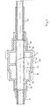
- Fig. 2 zeigt eine erfindungsgemäße Welle mit einem Antriebselement, das eine nahe den Verzahnungen ansetzende Hülse aufweist.
- 1 shows a shaft according to the invention with a drive element which attaches to the hub of the toothed disks,
- Fig. 2 shows a shaft according to the invention with a drive element which has a sleeve which starts close to the toothings.
In Fig. 1 ist eine Getriebewelle gezeigt, die eine Hohlwelle 1 umfaßt, in die jeweils am Ende Rohrstücke 2, 3 eingeschoben sind, und auf das ein Rohrstück 4 in Überdeckung mit dem letztgenannten aufgeschoben ist. Auf die so gebildete Hohlwelle ist ein Antriebselement 6 aufge schoben und durch inneres plastisches Verformen der Hohlwelle kraft- bzw. reibschlüssig festgelegt. Das Antriebselement 6 besteht aus zwei Zahnscheiben 9, 10, die durch eine an deren Naben ansetzende Hülse 11 miteinander verbunden sind, wobei letztere unmittelbar auf der Hohlwelle 1 aufsitzt. An der Zahnscheibe 10 sind beispielhaft umfangsverteilte Verstärkungsrippen 5 angedeutet. Auf die Hohlwelle 1 sind weiterhin noch aus Lagerwerkstoff bestehende Rohrstücke 12, 13 aufgeschoben, die als Laufbahn für Wälzlager dienen, wobei in das letztgenannte das Rohrstück 4 eingesteckt ist, das seinerseits zusammen mit dem Rohrstück 3 das Ende der Hohlwelle 1 einspannt.In Fig. 1, a transmission shaft is shown, which comprises a hollow shaft 1, into each of which
In Fig. 2 ist eine im wesentlichen durchgehende Hohlwelle 21 erkennbar, in die jeweils am Ende Rohrstücke 22, 23 eingesteckt sind. Auf die Hohlwelle ist ein Antriebselement 26 aufgeschoben, das zwei Zahnscheiben 29, 30 umfaßt, die über eine in der Nähe der Verzahnungen ansetzende Hülse 31 verbunden sind. Im Bereich der Naben schließen sich jeweils Hülsenansätze 14, 15 an die Zahnscheiben an, die unmittelbar die kraft- bzw. reibschlüssige Verbindung zur Hohlwelle 21 herstellen. In der oberen Bildhälfte ist eine in Umfangsrichtung liegende ringförmige Verstärkungsrippe 7 gezeigt, in der unteren Bildhälfte sind alternativ umfangsverteilte längsverlaufende Verstärkungsrippen 8 angedeutet. Auf die Hülsenansätze 14, 15 sind jeweils Rohrstücke 32, 33 aus Lagerwerkstoff aufgeschoben, die sich abgestuft fortsetzen und im Anschluß an die Hülsenansätze unmittelbar mit der Hohlwelle 21 reibschlüssigen Kontakt haben.An essentially continuous
- 1, 21 Rohrstück1, 21 pipe section
- 2, 22 Rohrstück2, 22 pipe section
- 3, 23 Rohrstück3, 23 pipe section
- 4 Rohrstück4 pipe section
- 5 Verstärkungsrippe5 reinforcement rib
- 6, 26 Antriebselement6, 26 drive element
- 7 Verstärkungsrippe7 reinforcement rib
- 8 Verstärkungsrippe8 reinforcement rib
- 9, 29 Zahnscheibe9, 29 tooth lock washer
- 10, 30 Zahnscheibe10, 30 tooth lock washer
- 11, 31 Verbindungshülse11, 31 connecting sleeve
- 12, 32 Lagerring12, 32 bearing ring
- 13, 33 Lagerring13, 33 bearing ring
- 14 Hülsenansatz14 sleeve approach
- 15 Hülsenansatz15 sleeve approach
Claims (12)
dadurch gekennzeichnet,
daß zumindest ein Antriebselement (6, 26) mit mindestens zwei durch eine Hülse (11, 31) verbundene Zahnscheiben (9, 10; 29, 30) unterschiedlichen Durchmessers in einstückiger Bauweise vorgesehen ist.1.Built transmission shaft, in which individual drive elements, in particular gearwheels, are fixed in a rotationally fixed manner on a hollow shaft, the connection between the hollow shaft and drive elements being effected essentially by force or frictional engagement between the plastically widened hollow shaft and the elastically prestressed drive elements,
characterized,
that at least one drive element (6, 26) with at least two toothed disks (9, 10; 29, 30) of different diameters connected by a sleeve (11, 31) is provided in a one-piece construction.
dadurch gekennzeichnet,
daß zwischen den zumindest zwei Zahnscheiben (9, 10) jeweils eine an deren Nabe ansetzende Hülse (11) ausgebildet ist, die in reibschlüssiger Verbindung auf der Hohlwelle (1) sitzt (Fig. 1).2. shaft according to claim 1,
characterized,
that between each of the at least two toothed disks (9, 10) is formed a sleeve (11) which attaches to their hub and which is seated in a frictional connection on the hollow shaft (1) (FIG. 1).
dadurch gekennzeichnet,
daß zwischen den zumindest zwei Zahnscheiben (29, 30) eine in der Nähe der Verzahnungen ansetzende Hülse (31) ausgebildet ist, die radialen Abstand zur Hohlwelle (21) aufweist (Fig. 2).3. shaft according to claim 1,
characterized,
that between the at least two toothed disks (29, 30) is formed a sleeve (31) which is positioned in the vicinity of the toothing and has a radial distance from the hollow shaft (21) (Fig. 2).
dadurch gekennzeichnet,
daß beidseitig an die Zahnscheiben (29, 30) anschliessend jeweils ein Hülsenansatz (14, 15) ausgebildet ist, der an der reibschlüssigen Verbindung mit der Hohlwelle (21) beteiligt ist.4. shaft according to claim 3,
characterized,
that on both sides of the toothed disks (29, 30), a sleeve extension (14, 15) is formed, which is involved in the frictional connection with the hollow shaft (21).
dadurch gekennzeichnet,
daß die Hülsenansätze (14, 15) sich jeweils axial nach außen an die Zahnscheiben (29, 30) anschließen.5. shaft according to claim 4,
characterized,
that the sleeve lugs (14, 15) each connect axially outwards to the toothed disks (29, 30).
dadurch gekennzeichnet,
daß die Hülsenansätze sich jeweils axial nach innen an die Zahnscheiben anschließen (ohne Fig.)6. shaft according to claim 4,
characterized,
that the sleeve attachments connect axially inwards to the toothed lock washers (without Fig.)
dadurch gekennzeichnet,
daß innerhalb der nahe den Verzahnungen ansetzenden Hülse (31) Umfangsrippen (7) oder längsgerichtete Rippen (8) zwischen den Zahnscheiben (29, 30) eingezogen sind.7. Shaft according to one of claims 3 to 6,
characterized,
that circumferential ribs (7) or longitudinal ribs (8) are drawn in between the toothed disks (29, 30) within the sleeve (31) which starts near the toothing.
dadurch gekennzeichnet,
daß die Hohlwelle aus mehreren ineinandergesteckten Rohrstücken (1, 2, 3, 4; 31, 22, 23) und/oder Hülsen (12, 13; 32, 33) zusammengesetzt ist, die im Bereich ihrer radialen Überdeckung zumindest abschnittsweise miteinander verbunden sind.8. Shaft according to one of claims 1 to 7,
characterized,
that the hollow shaft is composed of several nested pipe sections (1, 2, 3, 4; 31, 22, 23) and / or sleeves (12, 13; 32, 33), which are connected to one another at least in sections in the area of their radial overlap.
dadurch gekennzeichnet,
daß auf die auf einem inneren Teil (21) der Hohlwelle aufsitzenden Hülsenansätze (14, 15) Rohrstücke (32, 33) aufgeschoben sind, die nach dem plastischen Umformen der Hohlwelle (21) gegenüber den Hülsenansätzen (14, 15) elastisch vorgespannt sind.9. waves according to one of claims 3 to 8,
characterized,
that on the inner part (21) of the hollow shaft sleeve extensions (14, 15) tube pieces (32, 33) are pushed, which are elastically biased after the plastic deformation of the hollow shaft (21) relative to the sleeve extensions (14, 15).
dadurch gekennzeichnet,
daß die Rohrstücke (32, 33) als Lagerinnenringe von Wälzlagern dienen.10. shaft according to claim 9,
characterized,
that the pipe sections (32, 33) serve as inner bearing rings of rolling bearings.
dadurch gekennzeichnet,
daß die Antriebselemente (6, 26) mit mehreren Zahnscheiben aus Gußwerkstoff bestehen.11. Shaft according to one of claims 1 to 10,
characterized,
that the drive elements (6, 26) consist of a plurality of toothed disks made of cast material.
dadurch gekennzeichnet,
daß der Werkstoff der aufgeschobenen Rohrstücke (12, 13; 32, 33) eine höhere Streckgrenze hat als der jeweils dazu relativ radial innenliegende Teil der Hohlwelle (1, 2, 3, 4; 21, 22, 23).12. Shaft according to one of claims 3 to 11,
characterized,
that the material of the pushed-on pipe sections (12, 13; 32, 33) has a higher yield strength than the part of the hollow shaft (1, 2, 3, 4; 21, 22, 23) that is relatively radially inside.
Applications Claiming Priority (2)
| Application Number | Priority Date | Filing Date | Title |
|---|---|---|---|
| DE3805775 | 1988-02-24 | ||
| DE3805775A DE3805775A1 (en) | 1988-02-24 | 1988-02-24 | BUILT GEAR SHAFT |
Publications (3)
| Publication Number | Publication Date |
|---|---|
| EP0330931A2 true EP0330931A2 (en) | 1989-09-06 |
| EP0330931A3 EP0330931A3 (en) | 1990-06-13 |
| EP0330931B1 EP0330931B1 (en) | 1994-04-13 |
Family
ID=6348072
Family Applications (1)
| Application Number | Title | Priority Date | Filing Date |
|---|---|---|---|
| EP89102734A Expired - Lifetime EP0330931B1 (en) | 1988-02-24 | 1989-02-17 | Assembled gear axle |
Country Status (10)
| Country | Link |
|---|---|
| US (1) | US5000612A (en) |
| EP (1) | EP0330931B1 (en) |
| JP (1) | JP2805320B2 (en) |
| KR (2) | KR890013390A (en) |
| BR (1) | BR8900830A (en) |
| CA (2) | CA1300050C (en) |
| DE (2) | DE3805775A1 (en) |
| ES (1) | ES2054896T3 (en) |
| IN (1) | IN171473B (en) |
| MX (1) | MX172869B (en) |
Families Citing this family (8)
| Publication number | Priority date | Publication date | Assignee | Title |
|---|---|---|---|---|
| SE519042C2 (en) * | 1998-04-22 | 2002-12-23 | Winkvistbolagen Smidesprodukte | Clamping sleeve for absorbing axial forces in a mechanical joint, use of clamping sleeve and method for axially fixing drives stored on a shaft with such clamping sleeve |
| BRPI0520462A2 (en) * | 2005-08-04 | 2009-05-12 | Neumayer Tekfor Holding Gmbh | gearbox, especially for automobiles, and axle or axles for such and process for producing such axles |
| JP4395523B2 (en) * | 2007-04-18 | 2010-01-13 | 三菱重工業株式会社 | Blow mode door for vehicle air conditioner and vehicle air conditioner using the same |
| DE102011079992A1 (en) * | 2011-07-28 | 2013-01-31 | Schaeffler Technologies AG & Co. KG | Gear device for a gear train |
| EP2551539A1 (en) * | 2011-07-28 | 2013-01-30 | Schaeffler Technologies AG & Co. KG | Gear wheel device for a gear train |
| DE102013100527A1 (en) * | 2013-01-18 | 2014-07-24 | Rolls-Royce Deutschland Ltd & Co Kg | Gear wheel device installed in auxiliary gear box device of jet engine in aircraft, has toothed portion whose teeth sections are provided with rows of teeth that are interconnected in radial direction extending over gear wheel portion |
| US9759098B1 (en) | 2016-09-09 | 2017-09-12 | William Cullen Chapman, Jr. | Valvetrain conversion kit for an engine |
| CN112873182A (en) * | 2021-01-25 | 2021-06-01 | 中国科学院合肥物质科学研究院 | High-precision large-load output end |
Citations (6)
| Publication number | Priority date | Publication date | Assignee | Title |
|---|---|---|---|---|
| CH98614A (en) * | 1920-06-28 | 1923-04-02 | Deutsch Luxemburgische Bergwer | Sheet steel pulley. |
| FR744131A (en) * | 1933-04-12 | |||
| DE924666C (en) * | 1951-08-08 | 1955-03-07 | Porsche Kg | Double gears, especially sliding gears for speed change gears |
| DE3425600A1 (en) * | 1984-07-06 | 1986-01-16 | Zahnradwerk Neuenstein GmbH & Co., 7113 Neuenstein | HOLLOW WAVE |
| DE8713285U1 (en) * | 1987-10-02 | 1987-12-23 | Interatom | Drive shaft with drive elements attached in groups. |
| EP0328007A2 (en) * | 1988-02-07 | 1989-08-16 | Emitec Gesellschaft für Emissionstechnologie mbH | Assembled gear axle |
Family Cites Families (10)
| Publication number | Priority date | Publication date | Assignee | Title |
|---|---|---|---|---|
| CH9614A (en) * | 1895-01-16 | 1895-08-15 | Favre Louis Marius | New compensating balance for watches and chronometers |
| GB190015675A (en) * | 1900-09-04 | 1901-07-06 | John Forbes Scott | Improvements in the Speed Gear of Motor Cars and like Vehicles or Machines. |
| US1678582A (en) * | 1921-05-10 | 1928-07-24 | Westinghouse Gear And Dynamome | Gear structure |
| US3674292A (en) * | 1969-10-15 | 1972-07-04 | Amp Inc | Tubular connection devices |
| JPS5214860U (en) * | 1975-07-17 | 1977-02-02 | ||
| JPS5246141U (en) * | 1975-09-29 | 1977-04-01 | ||
| DE2546802C3 (en) * | 1975-10-18 | 1979-08-09 | Kloeckner-Humboldt-Deutz Ag, 5000 Koeln | Cam wager for reciprocating engines |
| JPS57113230U (en) * | 1980-12-29 | 1982-07-13 | ||
| JPS58133616U (en) * | 1982-03-03 | 1983-09-08 | 新中央工業株式会社 | Clutch part of transmission gear |
| DE3530600A1 (en) * | 1985-08-27 | 1987-03-05 | Interatom | METHOD FOR FIXING DRIVE ELEMENTS ON A HOLLOW SHAFT |
-
1988
- 1988-02-24 DE DE3805775A patent/DE3805775A1/en active Granted
-
1989
- 1989-02-06 IN IN108/CAL/89A patent/IN171473B/en unknown
- 1989-02-16 MX MX014958A patent/MX172869B/en unknown
- 1989-02-17 DE DE58907422T patent/DE58907422D1/en not_active Expired - Fee Related
- 1989-02-17 EP EP89102734A patent/EP0330931B1/en not_active Expired - Lifetime
- 1989-02-17 ES ES89102734T patent/ES2054896T3/en not_active Expired - Lifetime
- 1989-02-22 JP JP1040406A patent/JP2805320B2/en not_active Expired - Lifetime
- 1989-02-22 CA CA000591799A patent/CA1300050C/en not_active Expired - Lifetime
- 1989-02-23 BR BR898900830A patent/BR8900830A/en not_active IP Right Cessation
- 1989-02-23 CA CA000591774A patent/CA1322477C/en not_active Expired - Fee Related
- 1989-02-24 KR KR1019890002184A patent/KR890013390A/en not_active IP Right Cessation
- 1989-02-24 KR KR1019890002184A patent/KR910009755B1/en active
- 1989-02-24 US US07/315,521 patent/US5000612A/en not_active Expired - Fee Related
Patent Citations (8)
| Publication number | Priority date | Publication date | Assignee | Title |
|---|---|---|---|---|
| FR744131A (en) * | 1933-04-12 | |||
| CH98614A (en) * | 1920-06-28 | 1923-04-02 | Deutsch Luxemburgische Bergwer | Sheet steel pulley. |
| DE924666C (en) * | 1951-08-08 | 1955-03-07 | Porsche Kg | Double gears, especially sliding gears for speed change gears |
| DE3425600A1 (en) * | 1984-07-06 | 1986-01-16 | Zahnradwerk Neuenstein GmbH & Co., 7113 Neuenstein | HOLLOW WAVE |
| DE8713285U1 (en) * | 1987-10-02 | 1987-12-23 | Interatom | Drive shaft with drive elements attached in groups. |
| EP0309899A1 (en) * | 1987-10-02 | 1989-04-05 | Emitec Gesellschaft für Emissionstechnologie mbH | Motor shaft with mounted groups of drive units |
| EP0328007A2 (en) * | 1988-02-07 | 1989-08-16 | Emitec Gesellschaft für Emissionstechnologie mbH | Assembled gear axle |
| DE3803684A1 (en) * | 1988-02-07 | 1989-08-17 | Emitec Emissionstechnologie | BUILT GEAR SHAFT |
Also Published As
| Publication number | Publication date |
|---|---|
| JPH01250609A (en) | 1989-10-05 |
| US5000612A (en) | 1991-03-19 |
| DE3805775C2 (en) | 1991-09-19 |
| JP2805320B2 (en) | 1998-09-30 |
| DE58907422D1 (en) | 1994-05-19 |
| CA1300050C (en) | 1992-05-05 |
| ES2054896T3 (en) | 1994-08-16 |
| EP0330931A3 (en) | 1990-06-13 |
| IN171473B (en) | 1992-10-24 |
| KR890013390A (en) | 1989-09-22 |
| DE3805775A1 (en) | 1989-09-07 |
| CA1322477C (en) | 1993-09-28 |
| MX172869B (en) | 1994-01-18 |
| EP0330931B1 (en) | 1994-04-13 |
| KR910009755B1 (en) | 1991-11-29 |
| BR8900830A (en) | 1989-10-17 |
Similar Documents
| Publication | Publication Date | Title |
|---|---|---|
| EP0683333B1 (en) | Axle drive differential for motor vehicles | |
| EP1649197B1 (en) | Planet carrier for a gearbox | |
| DE3126192C2 (en) | ||
| DE2657306A1 (en) | VIBRATION DAMPER | |
| DE3150800A1 (en) | RADIAL DEFORMABLE BEARING AND TORSION DAMPING DEVICE, ESPECIALLY FRICTION COUPLING FOR MOTOR VEHICLES WITH SUCH A BEARING | |
| DE10333879A1 (en) | Planet carrier for transmission | |
| DE2850099A1 (en) | PLANETARY GEAR GEAR AND ITS ARRANGEMENT | |
| DE4020998C2 (en) | ||
| DE2848355C2 (en) | Shaft-hub connection | |
| EP0330931A2 (en) | Assembled gear axle | |
| DE2906627C2 (en) | ||
| WO2009095056A2 (en) | Differential cage made of half shells and method for producing a differential cage | |
| DE1625051C3 (en) | Three-part hydrodynamic torque converter | |
| EP0864779B1 (en) | Differential,particularly for the axle drive of a motor vehicle | |
| DE19904134A1 (en) | Clutch boss for supporting friction pads in multi-disk clutches has sheet metal strip fitted around circumference to match profile | |
| EP0406922B1 (en) | Wheel unit | |
| DE3805777C2 (en) | ||
| DE3101162A1 (en) | "EXHAUST TURBOCHARGER" | |
| DE3412169C1 (en) | Tensioner pulley unit | |
| DE19912719A1 (en) | Planetary gear for an automotive automatic gearbox able to accommodate and transmit higher torque values | |
| DE19931760A1 (en) | Housing and friction surface unit for hydrodynamic coupling esp. torque converter has housing and friction surface element with friction surface areas and structured surfaces | |
| DE3621188C2 (en) | ||
| DE19853802C2 (en) | Stress wave gear | |
| DE3539704A1 (en) | POWER TRANSMISSION ARRANGEMENT, ESPECIALLY FOR MOTOR VEHICLES, HYDRAULIC CLUTCH ORGAN WITH SUCH A POWER TRANSMISSION ARRANGEMENT AND APPARATUS APPARATUS FOR MEASURING THE MOVEMENT AND METHOD THEREOF | |
| EP0087071A1 (en) | Brake disc, in particular for disc brakes of rail vehicles |
Legal Events
| Date | Code | Title | Description |
|---|---|---|---|
| PUAI | Public reference made under article 153(3) epc to a published international application that has entered the european phase |
Free format text: ORIGINAL CODE: 0009012 |
|
| 17P | Request for examination filed |
Effective date: 19890217 |
|
| AK | Designated contracting states |
Kind code of ref document: A2 Designated state(s): BE CH DE ES FR GB IT LI NL SE |
|
| PUAL | Search report despatched |
Free format text: ORIGINAL CODE: 0009013 |
|
| AK | Designated contracting states |
Kind code of ref document: A3 Designated state(s): BE CH DE ES FR GB IT LI NL SE |
|
| 17Q | First examination report despatched |
Effective date: 19910808 |
|
| GRAA | (expected) grant |
Free format text: ORIGINAL CODE: 0009210 |
|
| AK | Designated contracting states |
Kind code of ref document: B1 Designated state(s): BE CH DE ES FR GB IT LI NL SE |
|
| PG25 | Lapsed in a contracting state [announced via postgrant information from national office to epo] |
Ref country code: NL Effective date: 19940413 Ref country code: BE Effective date: 19940413 |
|
| REF | Corresponds to: |
Ref document number: 58907422 Country of ref document: DE Date of ref document: 19940519 |
|
| ITF | It: translation for a ep patent filed |
Owner name: SOCIETA' ITALIANA BREVETTI S.P.A. |
|
| GBT | Gb: translation of ep patent filed (gb section 77(6)(a)/1977) |
Effective date: 19940708 |
|
| REG | Reference to a national code |
Ref country code: ES Ref legal event code: FG2A Ref document number: 2054896 Country of ref document: ES Kind code of ref document: T3 |
|
| ET | Fr: translation filed | ||
| NLV1 | Nl: lapsed or annulled due to failure to fulfill the requirements of art. 29p and 29m of the patents act | ||
| EAL | Se: european patent in force in sweden |
Ref document number: 89102734.4 |
|
| PLBE | No opposition filed within time limit |
Free format text: ORIGINAL CODE: 0009261 |
|
| STAA | Information on the status of an ep patent application or granted ep patent |
Free format text: STATUS: NO OPPOSITION FILED WITHIN TIME LIMIT |
|
| PG25 | Lapsed in a contracting state [announced via postgrant information from national office to epo] |
Ref country code: LI Effective date: 19950228 Ref country code: CH Effective date: 19950228 |
|
| 26N | No opposition filed | ||
| PGFP | Annual fee paid to national office [announced via postgrant information from national office to epo] |
Ref country code: GB Payment date: 20010112 Year of fee payment: 13 |
|
| PGFP | Annual fee paid to national office [announced via postgrant information from national office to epo] |
Ref country code: SE Payment date: 20010205 Year of fee payment: 13 Ref country code: FR Payment date: 20010205 Year of fee payment: 13 Ref country code: DE Payment date: 20010205 Year of fee payment: 13 |
|
| PGFP | Annual fee paid to national office [announced via postgrant information from national office to epo] |
Ref country code: ES Payment date: 20010220 Year of fee payment: 13 |
|
| REG | Reference to a national code |
Ref country code: GB Ref legal event code: IF02 |
|
| PG25 | Lapsed in a contracting state [announced via postgrant information from national office to epo] |
Ref country code: GB Free format text: LAPSE BECAUSE OF NON-PAYMENT OF DUE FEES Effective date: 20020217 |
|
| PG25 | Lapsed in a contracting state [announced via postgrant information from national office to epo] |
Ref country code: SE Free format text: LAPSE BECAUSE OF NON-PAYMENT OF DUE FEES Effective date: 20020218 Ref country code: ES Free format text: LAPSE BECAUSE OF NON-PAYMENT OF DUE FEES Effective date: 20020218 |
|
| PG25 | Lapsed in a contracting state [announced via postgrant information from national office to epo] |
Ref country code: DE Free format text: LAPSE BECAUSE OF NON-PAYMENT OF DUE FEES Effective date: 20020903 |
|
| EUG | Se: european patent has lapsed |
Ref document number: 89102734.4 |
|
| GBPC | Gb: european patent ceased through non-payment of renewal fee |
Effective date: 20020217 |
|
| PG25 | Lapsed in a contracting state [announced via postgrant information from national office to epo] |
Ref country code: FR Free format text: LAPSE BECAUSE OF NON-PAYMENT OF DUE FEES Effective date: 20021031 |
|
| REG | Reference to a national code |
Ref country code: FR Ref legal event code: ST |
|
| REG | Reference to a national code |
Ref country code: ES Ref legal event code: FD2A Effective date: 20030922 |
|
| PG25 | Lapsed in a contracting state [announced via postgrant information from national office to epo] |
Ref country code: IT Free format text: LAPSE BECAUSE OF NON-PAYMENT OF DUE FEES;WARNING: LAPSES OF ITALIAN PATENTS WITH EFFECTIVE DATE BEFORE 2007 MAY HAVE OCCURRED AT ANY TIME BEFORE 2007. THE CORRECT EFFECTIVE DATE MAY BE DIFFERENT FROM THE ONE RECORDED. Effective date: 20050217 |