EP0330465B1 - Device for indicating bearings in azimuth and inclination - Google Patents
Device for indicating bearings in azimuth and inclination Download PDFInfo
- Publication number
- EP0330465B1 EP0330465B1 EP89301769A EP89301769A EP0330465B1 EP 0330465 B1 EP0330465 B1 EP 0330465B1 EP 89301769 A EP89301769 A EP 89301769A EP 89301769 A EP89301769 A EP 89301769A EP 0330465 B1 EP0330465 B1 EP 0330465B1
- Authority
- EP
- European Patent Office
- Prior art keywords
- sextant
- azimuth
- indicator
- visual
- setting
- Prior art date
- Legal status (The legal status is an assumption and is not a legal conclusion. Google has not performed a legal analysis and makes no representation as to the accuracy of the status listed.)
- Expired - Lifetime
Links
- 230000000007 visual effect Effects 0.000 claims abstract description 14
- 230000005236 sound signal Effects 0.000 claims abstract description 11
- 229910052753 mercury Inorganic materials 0.000 description 5
- QSHDDOUJBYECFT-UHFFFAOYSA-N mercury Chemical compound [Hg] QSHDDOUJBYECFT-UHFFFAOYSA-N 0.000 description 4
- 238000005286 illumination Methods 0.000 description 2
- 230000004075 alteration Effects 0.000 description 1
- 238000010586 diagram Methods 0.000 description 1
- 230000000694 effects Effects 0.000 description 1
- 150000002730 mercury Chemical class 0.000 description 1
- 230000001960 triggered effect Effects 0.000 description 1
Images

Classifications
-
- G—PHYSICS
- G01—MEASURING; TESTING
- G01C—MEASURING DISTANCES, LEVELS OR BEARINGS; SURVEYING; NAVIGATION; GYROSCOPIC INSTRUMENTS; PHOTOGRAMMETRY OR VIDEOGRAMMETRY
- G01C1/00—Measuring angles
- G01C1/08—Sextants
-
- H—ELECTRICITY
- H01—ELECTRIC ELEMENTS
- H01Q—ANTENNAS, i.e. RADIO AERIALS
- H01Q1/00—Details of, or arrangements associated with, antennas
- H01Q1/12—Supports; Mounting means
- H01Q1/125—Means for positioning
Definitions
- This invention relates to a device for indicating bearings in azimuth and inclination and which, in one aspect, can be used as a sextant and in another as a device to assist in setting up apparatus for receiving and/or transmitting electromagnetic wave signals, for example radio, television and telecommunications signals.
- DE-A-3 150 959 discloses a sextant which can be used for reading angles of inclination, there is also provision of visual indicator means for showing when the sextant parts are horizontal and vertical. There is however no provision for reading or indicating angles of azimuth.
- a sextant device includes a mirror located on a first part and an index mirror location on a second part, which is movable over an index scale, means for setting a predetermined angle of the second part on the index scale and means for producing a visual and/or audio signal when said first part is horizontal characterised by means for setting a predetermined angle of azimuth for said first part, said means acting on a second indicator means for producing a visual and/or audio signal when said present angle of azimuth is achieved by manipulating the altitude of the device.
- Third indicator means may also be included for producing a visual and/or audio signal when said first part is vertically upright.
- the device may also include means for visually observing the angle of azimuth and thus, means for visually setting and observing the angle of azimuth may include a magnetic compass with visual readout.
- One or more of the indicator signals can be indicated on the device and/or by means remote therefrom.
- the indicator means are electrically operated, for example, by an electrical battery which can be carried on the device itself.
- the device can include means for attaching it to apparatus for receiving and/or transmitting electromagnetic wave signals, for example radio, television and telecommunication signals and thus, the attachment means may be arranged to enable the device to be secured to the front of a television satellite dish receiver.
- apparatus for receiving and/or transmitting electromagnetic wave signals for example radio, television and telecommunication signals
- the attachment means may be arranged to enable the device to be secured to the front of a television satellite dish receiver.
- the attachment means may include a number of legs for connection to the rim of the dish of the receiver and, if desired, these car be adjustable to accommodate dishes of different dimensions.
- the device is generally in the form of the well known type of nautical sextant and comprises a first part in the form of a quadrant 1 which carries a scale 3 to indicate elevation angles and which is pivotally connected to a second part which is in the form of an elevation setting arm 2.
- the outer end of the arm 2 is provided with a pointer 4 which moves over the scale 3 and this indicates the relative angle between the two parts.
- the quadrant 1 is provided with a viewing eye piece 5 and a first reflecting mirror 6.
- the inner pivoted end 7 of the arm 2 is provided with a second mirror 8 to provide the well known type of nautical sextant.
- the outer end of the arm 2 is provided with an adjustment wheel 9 so that accurate movement of the arm 2 can be achieved, the wheel 9 acting through a worm and quadrant gear (not shown) in well known manner.
- the quadrant 1 is provide with a battery box 10 which carries a first mercury tilt switch 11. This switch is connected to first indicator means provided by a first light source 12 carried in the eye piece 5 which is illuminated when the quadrant 1 is horizontal.
- a compass 13 is also carried on the battery box 10 so that it is directly behind the horizon mirror 6 so that it can be read through the eye piece 5.
- means are provided for electrically reading the compass by mounting a sensor within the compass bowl which is triggered by a light source below the card and which passes through a hole in the card or a reflecting spot on the card when the sensor is mounted on one side of the card. This signal is passed to a second indicator means in the form of a second light source 14 which is also carried in the eye piece 5.
- a second mercury tilt switch 15 is mounted on the battery box 10 and is connected to a third indicator means in the form of a third light source 16, again carried in the eye piece 5.
- This mercury switch 15 is arranged so that the third light source 16 is illuminated when the quadrant 1 is vertically upright.
- a jack plug point 17 is provided on the battery box to enable suitable wire connections to be made to the illumination circuits and so that remote reading lights can be provided.
- the apparatus provided according to the invention enables it to be levelled for taking sights when away from a sea horizon.
- Land navigation is usually carried out at night by taking star sights, from tables it is possible to calculate the expected azimuth of any star. This azimuth is then set on the compass 13 and when the second light source 14 is illuminated the sextant is pointing directly at the star.
- the mercury tilt switches 11 and 15 ensure that when the first and third light sources 12 and 16 are illuminated the sextant is horizontal and vertical.
- the expected altitude of the star having previously been set on the arm 2 it is then easier to identify the star and take its present altitude using the sextant in the usual way with the mirror 8 acting as an index mirror and the mirror 6 acting as the horizon mirror.
- the device described above can also be used to assist in setting up apparatus for receiving and/or transmitting electro-magnetic wave signals.
- Such devices require a clear line of sight from a point on the ground where the receiver or transmitter is situation to, for example, a satellite in geo-static orbit. Unlike the stars such a satellite stays in a fixed direction relative to a point on the ground. From tables it is possible to calculate the azimuth and elevation from any given point.
- an aerial such as a satellite dish must have an uninterrupted line of sight to be able to receive a signal from the satellite and if the sextant is used to establish this line of sight, provided nothing appears in the index mirror 8 of the sextant at given settings the line of sight is clear.
- the arm 2 of the device is provided with a suitable mounting bracket 18 which is secured to attachment means 19 which carries three adjustable mounting legs 20.
- the mounting legs 20 are secured to the attachment means 19 by pivots 21 at one end and are provided with clamps 22 at their other ends so that they can be secured to the aerial dish receiver indicated by reference numeral 23. If desired the legs 20 can be adjustable in length to enable the device to be attached to satellite dishes of different dimensions.
- the satellite dish 23 is provided with mounting means of well known type (not shown) to enable it to be securely mounted and to enable it to be tilted in any desired direction.
- the device In order to set up the dish 23 the device is mounted on its legs 20 on the dish so that it is central at the front of the dish. With the required settings already on the device the remote reading lights (not shown) are attached in the jack plug 17 on the battery box and located behind the dish and adjacent to the mounting means. The dish is now adjusted to a suitable tilt by reading the remote reading display, and provided all lights are illuminated the dish will be pointed at the satellite. The line of sight having previously been cleared the dish is now either accurately lined up on the satellite or very close to such alignment which can be finely adjusted by making minor alterations to the setting whilst tuning into the received signal.
- the mounting bracket 18 can be omitted and the sextant can be used for taking accurate star sights even if a horizon is not available, again, the sextant type device can be used for establishing a line of sight for a receiving and/or transmitting device for electro-magnetic wave signals. With the bracket 18 attached it can, as described above, be used for accurately setting up receiving and/or transmitting apparatus.
- the light sources 12, 14, 16 can be replaced by means for producing an audio signal such as a buzzer or bell or again, such audio signal apparatus could be included along with the visual illumination means. Yet again the signals could be transmitted to some other form of electrical apparatus, especially for distant reading.
- the compass 13 which, in the arrangement described can provided a visual reading, can be replaced by a device which merely provides an illuminated and/or audio signal.
- the compass is of the face reading type but this could be replaced by a ribbon type compass or, for example, a non-magnetized electronic bearing indicator. If the compass is to be relied upon for visual signals however it is of course desirable that the compass reading should be visible through the horizon mirror 6.
- the compass 13 is mounted on the battery box 10 but if desired the battery box could be located on the other side of the quadrant 1 closer to the eye piece to facilitate the electrical connections.
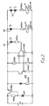
- Figure 2 shows an electronic circuit suitable for for with the apparatus and the same reference numerals are used to indicate similar parts to that shown in Figure 1.
- the two mercury tilt switches are identified by reference numerals 11 and 15 and the first and third light sources 12 and 16 are provided by light emitting diodes.
- the horizontal light source could be in the form of two diodes 12 to more easily distinguish it from the light source 16 indicating the vertical position.
- the means for reading the compass include a photo transistor indicated generally by reference numeral 24 which sends a signal to second light source 14 which is again in the form of a light emitting diode.
Landscapes
- Physics & Mathematics (AREA)
- Engineering & Computer Science (AREA)
- General Physics & Mathematics (AREA)
- Radar, Positioning & Navigation (AREA)
- Remote Sensing (AREA)
- Navigation (AREA)
- Devices For Indicating Variable Information By Combining Individual Elements (AREA)
- Testing, Inspecting, Measuring Of Stereoscopic Televisions And Televisions (AREA)
- Measuring Magnetic Variables (AREA)
- Audible And Visible Signals (AREA)
- Toys (AREA)
Priority Applications (1)
| Application Number | Priority Date | Filing Date | Title |
|---|---|---|---|
| AT89301769T ATE84874T1 (de) | 1988-02-23 | 1989-02-23 | Einrichtung zur anzeige von azimut- und neigungsrichtungen. |
Applications Claiming Priority (2)
| Application Number | Priority Date | Filing Date | Title |
|---|---|---|---|
| GB888804167A GB8804167D0 (en) | 1988-02-23 | 1988-02-23 | Device for indicating bearings in azimuth & inclination |
| GB8804167 | 1988-02-23 |
Publications (2)
| Publication Number | Publication Date |
|---|---|
| EP0330465A1 EP0330465A1 (en) | 1989-08-30 |
| EP0330465B1 true EP0330465B1 (en) | 1993-01-20 |
Family
ID=10632196
Family Applications (1)
| Application Number | Title | Priority Date | Filing Date |
|---|---|---|---|
| EP89301769A Expired - Lifetime EP0330465B1 (en) | 1988-02-23 | 1989-02-23 | Device for indicating bearings in azimuth and inclination |
Country Status (6)
| Country | Link |
|---|---|
| EP (1) | EP0330465B1 (show.php) |
| AT (1) | ATE84874T1 (show.php) |
| DE (1) | DE68904439T2 (show.php) |
| ES (1) | ES2037413T3 (show.php) |
| GB (1) | GB8804167D0 (show.php) |
| GR (1) | GR3007045T3 (show.php) |
Families Citing this family (1)
| Publication number | Priority date | Publication date | Assignee | Title |
|---|---|---|---|---|
| KR101038846B1 (ko) | 2009-02-23 | 2011-06-02 | 주식회사 케이티 | 안테나 설치 보조 장치 |
Family Cites Families (5)
| Publication number | Priority date | Publication date | Assignee | Title |
|---|---|---|---|---|
| FR1359336A (fr) * | 1963-03-15 | 1964-04-24 | Pinnule de site pour instruments d'optique à relever des gisements ou azimuts | |
| DE3150959A1 (de) * | 1981-12-23 | 1983-06-30 | Rainer H. 2850 Bremerhaven Aßkamp | Nautisches winkelmessgeraet mit schraeglagenanzeige |
| US4495706A (en) * | 1982-07-19 | 1985-01-29 | The Stolle Corporation | Alignment gage for dish antenna |
| FR2544486B1 (fr) * | 1983-04-12 | 1985-06-14 | Thomson Brandt | Outil de mesure de l'angle de site d'une antenne volumique |
| DE3540293A1 (de) * | 1985-11-13 | 1987-05-14 | Dieter Zeilinger | Optisches verfahren zur suche und eignungspruefung von standorten fuer satelliten-empfangsantennen |
-
1988
- 1988-02-23 GB GB888804167A patent/GB8804167D0/en active Pending
-
1989
- 1989-02-23 DE DE8989301769T patent/DE68904439T2/de not_active Expired - Fee Related
- 1989-02-23 EP EP89301769A patent/EP0330465B1/en not_active Expired - Lifetime
- 1989-02-23 AT AT89301769T patent/ATE84874T1/de active
- 1989-02-23 ES ES198989301769T patent/ES2037413T3/es not_active Expired - Lifetime
-
1993
- 1993-02-11 GR GR930400277T patent/GR3007045T3/el unknown
Also Published As
| Publication number | Publication date |
|---|---|
| DE68904439D1 (de) | 1993-03-04 |
| ATE84874T1 (de) | 1993-02-15 |
| DE68904439T2 (de) | 1993-05-13 |
| GR3007045T3 (show.php) | 1993-07-30 |
| ES2037413T3 (es) | 1993-06-16 |
| GB8804167D0 (en) | 1988-03-23 |
| EP0330465A1 (en) | 1989-08-30 |
Similar Documents
| Publication | Publication Date | Title |
|---|---|---|
| JPH03500334A (ja) | 衛星を用いた位置測定系の受信器を有する測量器及びそれの使用方法 | |
| US5949529A (en) | Modularized laser-based survey system | |
| US4495706A (en) | Alignment gage for dish antenna | |
| US2131952A (en) | Nocturnal antiaircraft fire control system | |
| CN108037501A (zh) | 一种能获取目标俯仰向角度的区域警戒雷达系统及方法 | |
| US6686889B1 (en) | Method and apparatus for antenna orientation and antenna with the same | |
| EP0330465B1 (en) | Device for indicating bearings in azimuth and inclination | |
| US4454658A (en) | Device to locate communication satellites | |
| US4650989A (en) | Alignment apparatus for photoelectric intrusion detector system | |
| US6292147B1 (en) | Self-positioning GPS antenna | |
| US7095378B1 (en) | Satellite dish sighting apparatus and alignment system | |
| US4225867A (en) | Orientation system | |
| US2475975A (en) | Apparatus for direction finding | |
| US4866849A (en) | Surveying target with high intensity discharge lamp | |
| US4352556A (en) | Reflector for electrooptical distance measurement | |
| US2462077A (en) | Navigational system | |
| US2608001A (en) | Indicating instrument | |
| US4674873A (en) | Satellite locator apparatus | |
| US2547310A (en) | Photoelectric, liquid-level inclinometer | |
| US2027528A (en) | Navigational guide system | |
| US3864015A (en) | Visual bearing instrument | |
| US2208209A (en) | Radio direction finder | |
| GB2211609A (en) | Alignment device | |
| CN207965139U (zh) | 一种能获取目标俯仰角度的区域警戒雷达系统 | |
| US20050241165A1 (en) | Device for faciltating the aiming of an antenna enabling signals transmitted by one or several satelites to be picked up |
Legal Events
| Date | Code | Title | Description |
|---|---|---|---|
| PUAI | Public reference made under article 153(3) epc to a published international application that has entered the european phase |
Free format text: ORIGINAL CODE: 0009012 |
|
| AK | Designated contracting states |
Kind code of ref document: A1 Designated state(s): AT BE CH DE ES FR GB GR IT LI LU NL SE |
|
| 17P | Request for examination filed |
Effective date: 19891109 |
|
| 17Q | First examination report despatched |
Effective date: 19910122 |
|
| GRAA | (expected) grant |
Free format text: ORIGINAL CODE: 0009210 |
|
| AK | Designated contracting states |
Kind code of ref document: B1 Designated state(s): AT BE CH DE ES FR GB GR IT LI LU NL SE |
|
| REF | Corresponds to: |
Ref document number: 84874 Country of ref document: AT Date of ref document: 19930215 Kind code of ref document: T |
|
| ITF | It: translation for a ep patent filed | ||
| PGFP | Annual fee paid to national office [announced via postgrant information from national office to epo] |
Ref country code: SE Payment date: 19930219 Year of fee payment: 5 |
|
| PGFP | Annual fee paid to national office [announced via postgrant information from national office to epo] |
Ref country code: LU Payment date: 19930224 Year of fee payment: 5 |
|
| PGFP | Annual fee paid to national office [announced via postgrant information from national office to epo] |
Ref country code: GR Payment date: 19930225 Year of fee payment: 5 Ref country code: CH Payment date: 19930225 Year of fee payment: 5 |
|
| PGFP | Annual fee paid to national office [announced via postgrant information from national office to epo] |
Ref country code: AT Payment date: 19930226 Year of fee payment: 5 |
|
| PGFP | Annual fee paid to national office [announced via postgrant information from national office to epo] |
Ref country code: NL Payment date: 19930228 Year of fee payment: 5 |
|
| REF | Corresponds to: |
Ref document number: 68904439 Country of ref document: DE Date of ref document: 19930304 |
|
| ET | Fr: translation filed | ||
| PGFP | Annual fee paid to national office [announced via postgrant information from national office to epo] |
Ref country code: BE Payment date: 19930318 Year of fee payment: 5 |
|
| EPTA | Lu: last paid annual fee | ||
| REG | Reference to a national code |
Ref country code: ES Ref legal event code: FG2A Ref document number: 2037413 Country of ref document: ES Kind code of ref document: T3 |
|
| REG | Reference to a national code |
Ref country code: GR Ref legal event code: FG4A Free format text: 3007045 |
|
| PLBE | No opposition filed within time limit |
Free format text: ORIGINAL CODE: 0009261 |
|
| STAA | Information on the status of an ep patent application or granted ep patent |
Free format text: STATUS: NO OPPOSITION FILED WITHIN TIME LIMIT |
|
| 26N | No opposition filed | ||
| PG25 | Lapsed in a contracting state [announced via postgrant information from national office to epo] |
Ref country code: LU Free format text: LAPSE BECAUSE OF NON-PAYMENT OF DUE FEES Effective date: 19940223 Ref country code: AT Effective date: 19940223 |
|
| PG25 | Lapsed in a contracting state [announced via postgrant information from national office to epo] |
Ref country code: SE Effective date: 19940224 |
|
| PG25 | Lapsed in a contracting state [announced via postgrant information from national office to epo] |
Ref country code: LI Effective date: 19940228 Ref country code: CH Effective date: 19940228 Ref country code: BE Effective date: 19940228 |
|
| BERE | Be: lapsed |
Owner name: WEATHERLAKE JOHN GEORGE PAX Effective date: 19940228 |
|
| PG25 | Lapsed in a contracting state [announced via postgrant information from national office to epo] |
Ref country code: GR Free format text: THE PATENT HAS BEEN ANNULLED BY A DECISION OF A NATIONAL AUTHORITY Effective date: 19940831 |
|
| PG25 | Lapsed in a contracting state [announced via postgrant information from national office to epo] |
Ref country code: NL Effective date: 19940901 |
|
| NLV4 | Nl: lapsed or anulled due to non-payment of the annual fee | ||
| REG | Reference to a national code |
Ref country code: CH Ref legal event code: PL |
|
| REG | Reference to a national code |
Ref country code: GR Ref legal event code: MM2A Free format text: 3007045 |
|
| EUG | Se: european patent has lapsed |
Ref document number: 89301769.9 Effective date: 19940910 |
|
| PGFP | Annual fee paid to national office [announced via postgrant information from national office to epo] |
Ref country code: FR Payment date: 19960802 Year of fee payment: 8 |
|
| PGFP | Annual fee paid to national office [announced via postgrant information from national office to epo] |
Ref country code: DE Payment date: 19960803 Year of fee payment: 8 |
|
| PGFP | Annual fee paid to national office [announced via postgrant information from national office to epo] |
Ref country code: ES Payment date: 19960813 Year of fee payment: 8 |
|
| PG25 | Lapsed in a contracting state [announced via postgrant information from national office to epo] |
Ref country code: ES Free format text: LAPSE BECAUSE OF NON-PAYMENT OF DUE FEES Effective date: 19970224 |
|
| PG25 | Lapsed in a contracting state [announced via postgrant information from national office to epo] |
Ref country code: FR Effective date: 19971030 |
|
| PG25 | Lapsed in a contracting state [announced via postgrant information from national office to epo] |
Ref country code: DE Effective date: 19971101 |
|
| REG | Reference to a national code |
Ref country code: FR Ref legal event code: ST |
|
| REG | Reference to a national code |
Ref country code: ES Ref legal event code: FD2A Effective date: 19990405 |
|
| PGFP | Annual fee paid to national office [announced via postgrant information from national office to epo] |
Ref country code: GB Payment date: 20000307 Year of fee payment: 12 |
|
| PG25 | Lapsed in a contracting state [announced via postgrant information from national office to epo] |
Ref country code: GB Free format text: LAPSE BECAUSE OF NON-PAYMENT OF DUE FEES Effective date: 20010223 |
|
| GBPC | Gb: european patent ceased through non-payment of renewal fee |
Effective date: 20010223 |
|
| PG25 | Lapsed in a contracting state [announced via postgrant information from national office to epo] |
Ref country code: IT Free format text: LAPSE BECAUSE OF NON-PAYMENT OF DUE FEES;WARNING: LAPSES OF ITALIAN PATENTS WITH EFFECTIVE DATE BEFORE 2007 MAY HAVE OCCURRED AT ANY TIME BEFORE 2007. THE CORRECT EFFECTIVE DATE MAY BE DIFFERENT FROM THE ONE RECORDED. Effective date: 20050223 |