EP0330409A2 - An engine brake control device for an automatic transmission - Google Patents
An engine brake control device for an automatic transmission Download PDFInfo
- Publication number
- EP0330409A2 EP0330409A2 EP89301634A EP89301634A EP0330409A2 EP 0330409 A2 EP0330409 A2 EP 0330409A2 EP 89301634 A EP89301634 A EP 89301634A EP 89301634 A EP89301634 A EP 89301634A EP 0330409 A2 EP0330409 A2 EP 0330409A2
- Authority
- EP
- European Patent Office
- Prior art keywords
- brake
- valve
- pressure
- engine
- hydraulic
- Prior art date
- Legal status (The legal status is an assumption and is not a legal conclusion. Google has not performed a legal analysis and makes no representation as to the accuracy of the status listed.)
- Granted
Links
Images


Classifications
-
- F—MECHANICAL ENGINEERING; LIGHTING; HEATING; WEAPONS; BLASTING
- F16—ENGINEERING ELEMENTS AND UNITS; GENERAL MEASURES FOR PRODUCING AND MAINTAINING EFFECTIVE FUNCTIONING OF MACHINES OR INSTALLATIONS; THERMAL INSULATION IN GENERAL
- F16H—GEARING
- F16H61/00—Control functions within control units of change-speed- or reversing-gearings for conveying rotary motion ; Control of exclusively fluid gearing, friction gearing, gearings with endless flexible members or other particular types of gearing
- F16H61/21—Providing engine brake control
-
- F—MECHANICAL ENGINEERING; LIGHTING; HEATING; WEAPONS; BLASTING
- F16—ENGINEERING ELEMENTS AND UNITS; GENERAL MEASURES FOR PRODUCING AND MAINTAINING EFFECTIVE FUNCTIONING OF MACHINES OR INSTALLATIONS; THERMAL INSULATION IN GENERAL
- F16H—GEARING
- F16H61/00—Control functions within control units of change-speed- or reversing-gearings for conveying rotary motion ; Control of exclusively fluid gearing, friction gearing, gearings with endless flexible members or other particular types of gearing
- F16H61/04—Smoothing ratio shift
- F16H61/06—Smoothing ratio shift by controlling rate of change of fluid pressure
- F16H61/061—Smoothing ratio shift by controlling rate of change of fluid pressure using electric control means
-
- F—MECHANICAL ENGINEERING; LIGHTING; HEATING; WEAPONS; BLASTING
- F16—ENGINEERING ELEMENTS AND UNITS; GENERAL MEASURES FOR PRODUCING AND MAINTAINING EFFECTIVE FUNCTIONING OF MACHINES OR INSTALLATIONS; THERMAL INSULATION IN GENERAL
- F16H—GEARING
- F16H59/00—Control inputs to control units of change-speed-, or reversing-gearings for conveying rotary motion
- F16H59/50—Inputs being a function of the status of the machine, e.g. position of doors or safety belts
- F16H2059/506—Wheel slip
-
- F—MECHANICAL ENGINEERING; LIGHTING; HEATING; WEAPONS; BLASTING
- F16—ENGINEERING ELEMENTS AND UNITS; GENERAL MEASURES FOR PRODUCING AND MAINTAINING EFFECTIVE FUNCTIONING OF MACHINES OR INSTALLATIONS; THERMAL INSULATION IN GENERAL
- F16H—GEARING
- F16H61/00—Control functions within control units of change-speed- or reversing-gearings for conveying rotary motion ; Control of exclusively fluid gearing, friction gearing, gearings with endless flexible members or other particular types of gearing
- F16H61/02—Control functions within control units of change-speed- or reversing-gearings for conveying rotary motion ; Control of exclusively fluid gearing, friction gearing, gearings with endless flexible members or other particular types of gearing characterised by the signals used
- F16H61/0202—Control functions within control units of change-speed- or reversing-gearings for conveying rotary motion ; Control of exclusively fluid gearing, friction gearing, gearings with endless flexible members or other particular types of gearing characterised by the signals used the signals being electric
- F16H61/0251—Elements specially adapted for electric control units, e.g. valves for converting electrical signals to fluid signals
- F16H2061/0258—Proportional solenoid valve
-
- F—MECHANICAL ENGINEERING; LIGHTING; HEATING; WEAPONS; BLASTING
- F16—ENGINEERING ELEMENTS AND UNITS; GENERAL MEASURES FOR PRODUCING AND MAINTAINING EFFECTIVE FUNCTIONING OF MACHINES OR INSTALLATIONS; THERMAL INSULATION IN GENERAL
- F16H—GEARING
- F16H61/00—Control functions within control units of change-speed- or reversing-gearings for conveying rotary motion ; Control of exclusively fluid gearing, friction gearing, gearings with endless flexible members or other particular types of gearing
- F16H61/04—Smoothing ratio shift
- F16H2061/0466—Smoothing shift shock by apply or release of band brake servos, e.g. overlap control of band brake and a clutch or vice versa
-
- F—MECHANICAL ENGINEERING; LIGHTING; HEATING; WEAPONS; BLASTING
- F16—ENGINEERING ELEMENTS AND UNITS; GENERAL MEASURES FOR PRODUCING AND MAINTAINING EFFECTIVE FUNCTIONING OF MACHINES OR INSTALLATIONS; THERMAL INSULATION IN GENERAL
- F16H—GEARING
- F16H61/00—Control functions within control units of change-speed- or reversing-gearings for conveying rotary motion ; Control of exclusively fluid gearing, friction gearing, gearings with endless flexible members or other particular types of gearing
- F16H61/04—Smoothing ratio shift
- F16H2061/0485—Smoothing ratio shift during range shift from neutral (N) to reverse (R)
-
- F—MECHANICAL ENGINEERING; LIGHTING; HEATING; WEAPONS; BLASTING
- F16—ENGINEERING ELEMENTS AND UNITS; GENERAL MEASURES FOR PRODUCING AND MAINTAINING EFFECTIVE FUNCTIONING OF MACHINES OR INSTALLATIONS; THERMAL INSULATION IN GENERAL
- F16H—GEARING
- F16H61/00—Control functions within control units of change-speed- or reversing-gearings for conveying rotary motion ; Control of exclusively fluid gearing, friction gearing, gearings with endless flexible members or other particular types of gearing
- F16H61/04—Smoothing ratio shift
- F16H2061/0488—Smoothing ratio shift during range shift from neutral (N) to drive (D)
-
- F—MECHANICAL ENGINEERING; LIGHTING; HEATING; WEAPONS; BLASTING
- F16—ENGINEERING ELEMENTS AND UNITS; GENERAL MEASURES FOR PRODUCING AND MAINTAINING EFFECTIVE FUNCTIONING OF MACHINES OR INSTALLATIONS; THERMAL INSULATION IN GENERAL
- F16H—GEARING
- F16H61/00—Control functions within control units of change-speed- or reversing-gearings for conveying rotary motion ; Control of exclusively fluid gearing, friction gearing, gearings with endless flexible members or other particular types of gearing
- F16H61/04—Smoothing ratio shift
- F16H61/06—Smoothing ratio shift by controlling rate of change of fluid pressure
- F16H61/065—Smoothing ratio shift by controlling rate of change of fluid pressure using fluid control means
- F16H61/067—Smoothing ratio shift by controlling rate of change of fluid pressure using fluid control means using an accumulator
-
- F—MECHANICAL ENGINEERING; LIGHTING; HEATING; WEAPONS; BLASTING
- F16—ENGINEERING ELEMENTS AND UNITS; GENERAL MEASURES FOR PRODUCING AND MAINTAINING EFFECTIVE FUNCTIONING OF MACHINES OR INSTALLATIONS; THERMAL INSULATION IN GENERAL
- F16H—GEARING
- F16H63/00—Control outputs from the control unit to change-speed- or reversing-gearings for conveying rotary motion or to other devices than the final output mechanism
- F16H63/02—Final output mechanisms therefor; Actuating means for the final output mechanisms
- F16H63/30—Constructional features of the final output mechanisms
- F16H63/3003—Band brake actuating mechanisms
Definitions
- the present invention relates to a hydraulic control device for an automatic transmission used with engine, in particular to a hydraulic control device for an automatic transmission mounted on an automobile, in detail relates to an engine-brake control device to control hydraulic pressure of a brake hydraulic servo which is used for a brake directly restraining certain element of a shift gear mechanism.
- an automatic transmission works an engine-brake, at a second range (or S range) or a L range, by actuating a second coast brake (at 2nd speed) restraining front and rear sun gear, or by actuating a first & reverse brake (at 1st speed).
- hydraulic servos for the second-coast brake and the first & reverse brake are applied with a modulator pressure from a second-coast modulator valve or a low-coast modulator valve.
- the above mentioned modulator valve reduces the line pressure and supplies it to the hydraulic servos of the second-coast brake and the first & reverse brake so that shift shock is reduced, however, the modulator valve, as shown in Fig.6 by dotted lines, the pressure is constantly reduced regardless of vehicle speed.
- a brake torque capacity X based on the governor valve is designed to be small at middle speed area Q because of a centrifugal force working on a governor weight, while the torque capacity is designed to be large at high speed area R. Subsequently, the brake torque capacity against necessary engine-brake torque capacity Y is not enough, so that a slip occurs. At the high speed area R, the brake torque capacity is too large against the necessary engine-brake torque capacity Y, so that sharp shift shock occurs.
- the present invention is purposed to solve the above mentioned disadvantages by controlling hydraulic pressure to a brake hydraulic servo through a pressure control valve (linear solenoid valve).
- a hydraulic control device for an automatic transmission including a brake directly restraining certain element of a shift gear mechanism, a hydraulic servo (B1) or (B3) to control the brake, shift valves (60), (61) to supply or drain the hydraulic pressure of the brake servo; modulator valves (66), (65) are situated in oil passages connected to the hydraulic servo (B1) or (B3), these modulator valves are controlled by a pressure control valve (S4) which is controlled by signals from a control unit (C) where the signals are produced based on a vehicle running conditions.
- a speed sensor (46) sends signals to the control unit (C), the unit (C) dispatches signals to the pressure control valve (S4) so that the hydraulic pressure of the hydraulic servo (B1) or (B3) is kept low when a vehicle speed is low while the hydraulic pressure of the servo is kept high when a vehicle speed is high.
- the control unit (C) receives signals from a brake sensor (47) which detects operation of a foot brake in addition to the signals from the sensor (46) so that when the foot brake is applied the pressure control valve (S4) is controlled to reduce the hydraulic pressure of the servo, which is varied according to a vehicle speed.
- the control unit (C) receives signals from a front wheel rotation detecting sensor (48) and a rear wheel rotation detecting sensor (49) and calculates the difference of rotation so that the pressure control valve (S4) keeps the hydraulic pressure of the servo low when rotation difference between the front and the rear wheel is large while the valve (S4) keeps the pressure of the servo high when rotation difference of the wheels is small.
- the brakes are a second-coast brake (B1) which is actuated at the second speed of other than D range, and a first & reverse brake (B3) which is actuated at the first speed.
- a line pressure (p) is applied from a port (b) from which the line pressure is applied at the second range and L range of a manual valve (51) through ports (b1), (f) of a 2-3 shift valve (61); ports (f1), (g) of a 1-2 shift valve (60); ports (g1), l(h) of a second-coast modulator valve (66).
- Draining pressure form the servo (B1) is drained from a check ball (91) without passing through the modulator valve (66).
- a line pressure (p) is applied from a port (c) from which the line pressure is applied at the L range of the manual valve (51) through ports (c1), (i) of the 2-3 shift valve (61); ports (i1), (j) of the low-coast modulator valve (65); ports (j1), (k) of the 1-2 shift valve (60); and a check ball (90).
- the second-coast modulator valve (66) has a control chamber (m2) where control hydraulic pressure from a port (m) of an accumulator control valve (72) is applied, and the low-coast modulator valve (65) has a control chamber (m3) where control hydraulic pressure from a port (m) of the accumulator control valve (72) is applied.
- the accumulator control valve (72) has a port (n1) where hydraulic pressure from ports (n), (n) of the pressure control valve (S4) which is controlled by electric signals of the control unit (C) which receives the signals from the speed sensor (46), the brake sensor (47), the front and rear wheel rotation sensors (48), (49) is applied.
- regulated pressure is applied to the port (n1) so that the line pressure applied to a port (p2) is regulated and such regulated pressure is taken out from port (m) of the accumulator control valve (72).
- a port (o) of the pressure control valve (S4) is applied with reduced pressure from a solenoid modulator valve(73).
- the following provisions are also possible: due to the signal of the brake sensor (47), the hydraulic pressure according to a vehicle speed is kept low when the foot brake is applied. And due to the signals of the front and rear wheel rotation sensors, the control unit (C) calculates rotation difference, and the engine-brake force is kept low when the rotation difference between the front and rear wheels is large.
- the line pressure from the port (b) of the manual valve (51) is applied to the port (g1) of the second-coast modulator valve (66) through the ports (b1), (f) of the 2-3 shift valve (61); the ports (f1), (g) of the 1-2 shift valve (60).
- the hydraulic pressure is regulated based on the con trol pressure of the control chamber (m2), then the regulated pressure is applied to the second-coast brake hydraulic servo B1).
- the pressure control valve (S4) is controlled by the signals from the control unit (C) where signal of each sensor (46), (47), (48), (49) are sent.
- the engine-brake hydraulic pressure is generated, as shown in Fig.6, having three areas: (D) - high constant pressure for high speed condition which is more than certain speed; (E) - hydraulic pressure is reduced proportional to a vehicle speed; (F) - low constant pressure for low speed condition. Or the engine-brake hydraulic pressure (G) which is proportional to a vehicle speed is generated.
- the line pressure is applied from the port (c) of the manual valve (51) to the port (i1) of the low-coast modulator valve (65) through the ports (c1), j) of the 2-3 shift valve (65).
- the line pressure is regulated based on the control pressure of the control chamber (m3) and applied to the first & reverse brake hydraulic servo (B3).
- the control pressure is generated by the pressure control valve (S4) and the accumulator control valve (72), then the engine-brake hydraulic pressure is also generated as shown in Fig.6 by continuous line and dotted lines.
- the means to control the modulator valve is not limited to the above accumulator control valve (72). It is of course possible to connect a regulated pressure generating means such as a linear solenoid valve directly to a control chamber of the modulator valve.
- An automatic transmission 1 as shown in Fig.2 and 3, has a torque converter 2, a planetary transmission gear mechanismn3 and a hydraulic control device 5 which are housed in a converter housing 6, a transmission case 7, an extension housing 9, a valve body 10 and an oil pan 11.
- the torque converter 2 has a lock-up clutch 12, so that rotation of an input member 13 is transmitted to an input shaft 15 of the transmission gear mechanism 3 through hydraulic flow of the torque converter 2 or the lock-up clutch 12.
- the shift gear mechanism 3 comprises a main transmission unit 21 including an over-drive planetary gear unit 17, a front planetary gear unit 19 and a rear planetary gear unit 20.
- the over-drive planetary gear unit 17 comprises a planetary pinion 22, a carrier 24 which is directly connected to the input shaft 15 and supports the pinion 22, a sun gear 23 which encloses the input shaft 15, and a ring gear 25 which is connected to an input shaft 26 of the main transmission mechanism 21.
- An over-drive direct clutch C0 and a one-way clutch F0 are situated between the carrier 24 and the sun gear 23, and an over- drive brake B0 is situated between the sun gear 23 and the case 7.
- the front planetary gear unit 19 comprises a planetary pinion 28, a carrier 29 which is directly connected to an output shaft 27 and supports the pinion 28, a sun gear 30a which encloses the output shaft 27 and is constituted integrally with a sun gear 30b of the rear planetary gear unit 20, and a ring gear 31 which is connected to the input shaft 26 through a forward clutch C1.
- a direct clutch C2 is situated between the input shaft 26 and the sun gear 30, a second-coast brake B1 composed of a band brake is situated between the sun gear 30 and the case 7, a one-way cltuch F1 and a second brake B2 are radially situated between the sun gear 30 and the case 7.
- the rear planetary gear unit 20 comprises a planetary pinion 32, a carrier 33 which supports the pinion 32, a sun gear 30b, and a ring gear 35 which directly connects to the output shaft 27.
- a first & reverse brake B3 and a one-way clutch F2 are situated radially between the carrier 33 and the case 7.
- Incidentally 36 in Fig.2 is an oil pump.
- the one-way clutch F0 is situated between a boss 23a of the sun gear 23 and a sleeve 24a of the carrier 24.
- a flange member 40 which constitutes a cylinder is extended from the bass 23a.
- the flange member 40 encloses a piston member 41 to form an hydraulic actuator of the clutch C0, the over-drive direct clutch C0 is situated between the sleeve 24a and an inner surface of the flange 40.
- the over-drive brake B0 is situated between an outer surface of the flange 40 and the case 7.
- a brim 42 is fixed on a peripheral part of the flange 40.
- a non-contacting type sensor 45 such as employing light or magnetic and the like is situated on the case 7 so that the sensor 45 faces plural through holes or slits which are formed on the brim 42.
- the sensor 45 is situated to detect rotation speed of the clutch C0, in other words, to detect rotation speed of the brim 42 which rotates together with the input member 15 at the first, second and third speeds.
- a speed sensor 46 which detects vehicle speed is situated in the extension case 9. Electric signals of the sensor 45, 46 and other sensors are sent to a control unit C to control solenoid valves S1, S2, S3 and S4 which are explained later.
- C0, C1 and C2 are hydraulic servos for each clutch
- B0, B1, B2 and B3 are hydraulic servos for each brake
- 2 is a torque converter
- 36 is an oil pump.
- 51 is a manual valve where a line pressure port p is connected to ports a, b, c and d which corresponds to ranges of R, P, N, D, S and L, as shown in the table in Fig.4.
- 52 is a primary regulator valve
- 53 is a throttle valve
- 55 is a secondary regulator valve
- 56 is a lock-up control valve
- 57 is a lock-up relay valve
- 58 is a solenoid relay valve
- 59 is a cutback valve.
- 60 is a 1-2 shift valve
- 61 is a 2-3 shift valve
- 62 is a 3-4 shift valve
- 63 is a reverse inhibit valve
- 65 is a low-coast modulator valve
- 66 is a second-coast modulator valve.
- 67 is an accumulator for the clutch C0
- 70 is an accumulator for the clutch C2
- 71 is an accumulator for the brake B2.
- 72 is an accumulator control valve which regulates hydraulic pressure applied to back pressure chamber 69a, 70a and 71a of the accumulator 69, 70 and 71, and controls the low-coast modulator valve 65 and the second-coast modulator valve 66.
- S1, S2 and S3 are solenoid valves to control the shift valves 60, 61 and 62.
- S4 is a linear solenoid valve, the S4 regulates hydraulic pressure from a solenoid regulator valve 73, and the regulated pressure is sent applied to the accumulator control valve 72.
- the engine-brake control device is to control a supply hydraulic pressure to the second-coast brake hydraulic servo B1 which operates at the second speed of the second range and the L range, and to the first & reverse brake hydraulic servo B3 which operates at the first speed of the L range.
- this engine-brake control device has; the second-coast modulator valve 66 and the low-coast modulator valve 65 which are situated in oil passages to the servos; the accumulator control valve 72 controlling these modulator valves; the linear solenoid valve S4 and the solenoid modulator valve 73.
- the port b, in the manual valve 51, where the line pressure is applied at the second range of the manual valve 51 is connecte to the port b1 of the 2-3 shift valve 61.
- the 2-3 shift valve 61 is in an upper-half position (which means the position of spool depicted in the right side of the spool in Fig.1) at the second speed, so that the port b1 and the port f are through.
- the port f is connected to the port f1 of the 1-2 shift valve 60.
- the 1-2 shift valve 60 is in a left-half position which means the position of spool depicted in the left side of the spool in Fig.1) at the second speed, so that the port f1 and the port g are through.
- the port g is connected to the port g1 of the second modulator valve 66.
- the hydraulic pressure at the port g1 is regulated by control pressure in a control chamber m2, and the regulated pressure is taken from the port h to the second-coast brake hydraulic servo B1.
- the drain pressure from the servo B1 is led to the port g of the 1-2 shift valve 60 through the check ball 91, and drained from the drain port EX.
- the port c, in the manual valve 51, where the line pressure p is applied at the L range of the manual valve 51 is connected to the port c1 of the 2-3 shift valve 61.
- the line pressure from the port c is applied to the lower chamber c2, so that the valve 61 is in the right-half position, thus the port c1 and the i are through.
- the port i is connected to the port i1 of the low-coast modulator valve 65.
- the pressure at the port i1 is regulated by control pressure of a control chamber m3, and this regulated pressure is taken from the port j to the port j1 of the 1-2 shift valve 60.
- the valve 60 At the first speed, the valve 60 is in the right-half position, so that the port j1 and the port k are through.
- the hydraulic pressure from the port k is applied to the first & reverse brake hydraulic servo B3 through a check ball 90.
- the check ball 90 has a port d1 which is connected to the port d of the manual valve 51, which the line pressure is applied at the reverse range, and a port k1 which is connected to the port k.
- a ball 90b in a sleeve 90a is moved so that the pressure is applied to the servo B3 from the port q.
- the accumulator control valve 72 has; a port p2 which the line pressure is applied; a first control chamber p1 by which the line pressure is applied on the top of spool; a second control chamber n1 which the control pressure from the linear solenoid valve S4 is applied; a regulating port m which regulates the line pressure of the port p2, and connects the control chamber m2, m3 of the second-coast modulator valve 66 and the low-coast modulator valve 66 respectively; a feedback chamber m1 whose hydraulic pressure works together with the pressure of the control chamber n1 and pressing force of the spring 72a against the line pressure off the control chamber p1.
- the linear solenoid valve S4 is controlled by electric signals of the control unit C which is based on the signals of speed sensor 46, brake sensor 47, front wheel rotation sensor 48 and rear wheel rotation sensor 49.
- the port o of the valve S4 is applied with pressure which is a reduced line pressure by the solenoid modulator valve 73, then the reduced line pressure is regulated in the valve S4 and is output to the ports n, n.
- the hydraulic pressure from the ports n, n is applied to the control chamber n1 of the accumulator control valve 72.
- the pressure from the port m of the accumulator control valve 72 is applied to the back pressure chamber 69a, 70a and 71a of the B0 accumulator, C2 accumulator and B2 accumulator as well as the control chamber m2, m3 of the modulator valves 66, 65.
- An oil passage through to the second-coast brake hydraulic servo B1 is connected to an upper control chamber r of the cutback valve 59 so that cutback operation by the cutback valve 59 is stopped when the second-coast brake B1 is actuated.
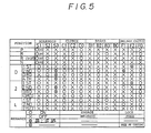
- the solenoid valves S1, S2 and S3; the clutches C0, C1 and C2; the brakes B0, B1, B2 and B3; the one-way clutches F0, F1 and F2; are operated at the positions of P, R, R(speed is more than 7 km/h), N, D, 2 and L ranges, as shown in Fig.5.
- the solenoid valve S1 is ON, so that the over-drive direct clutch C0, the one-way clutch F0, F2 and the forward clutch C1 are engaged, other elements are all released. Accordingly, all elements of the over-drive planetary gear unit 17 rotates together through the clutch C0 and the one-way clutch F0, thus rotation of the input shaft 15 is transmitted the input shaft 26 of the main transmission unit 21 without reducing rotation speed.
- rotation of the input shaft 26 is transmitted to the ring gear 31 of the front planetary gear unit 19, and transmitted to the carrier 29 and the output shaft 27 which is integrally connected with the carrier 29.
- the solenoid valve S2 is ON in addition to the solenoid valve S1.
- the over-drive direct clutch C0, the one-way clutch F0, the forward clutch C1, the one-way clutch F1 and the second brake B2 are engaged, and other elements are all released. Accordingly, the over-drive planetary gear 17 is still kept under the direct operating condition, the rotation of the input shaft 15 is transmitted to the input shaft 26 without reducing rotation speed.
- rotation of the input shaft 26 is transmitted to the ring gear 31 through the forward clutch C1, and the sun gear 30 is provided with torque in the left rotational direction through the pinion 28.
- the sun gear 30 is restrained in the left rotational direction by the operation of the one-way clutch F1 because of engagement of the brake B2, consequently, the planetary pinion 28 rotates and the carrier 29 rotates. Then the rotation of the carrier 29 is directly transmitted to the output shaft 27, namely the rotation is transmitted only through the front gear unit 19 to the output shaft 27.
- the control valve 72 is under the right-half position (Fig.1) by hydraulic pressure being applied to the first control chamber p1 through an orifice, and the line pressure applied from the port p2 is taken out from the port m to apply to the back pressure chamber 71a of the accumulator 71, from the above state of the control valve 72, the control pressure from the port m works to a bulged section of the spool, and the pressure, with the pressing force of the spring 72a, moves the spool against the line pressure of the first control chamber p1. Consequently the line pressure of the port p2 is reduced in accordance with the control pressure and taken out from the port m.
- the reduced pressure works from the feedback port m1 to a lower part of the spool 72, at the same time the reduced pressure is applied to the back pressure chamber 71b of the accumulator 71. Because of these motions, the accumulator back pressure is reduced by certain volume and certain duration of time. Furthermore, after certain time, the accumulator back pressure is gradually reduced based on the control pressure of from the linear solenoid valve S4, the output torque is smoothly varies. Thus, when shifting from the first speed to the second, shift-shock caused by engaging the second brake B2 is reduced, so that shift-up operation is conducted smoothly.
- the solenoid valve S1 is OFF, the over-drive direct clutch C0, the one-way clutch F0, the forward clutch C1, the direct clutch C2 and the second brake B2 are engaged, and other elements are all released.
- the over-drive planetary gear unit 17 is under the direct operating condition, and in the maim transmission mechanism 21, the elements of the front planetary gear unit 19 rotate together because the clutch C1 and C2 are engaged, thus rotation of the input shaft 26 is transmitted to the output shaft 27 without reducing rotation speed.
- the 2-3 shift valve 61 is switched due to the solenoid valve S4 being OFF, the direct clutch C2 is engaged, at this moment, as same as the B2 accumulator 71, certain hydraulic pressure is applied to the back pressure chamber 70a of the C2 accumulator 70, so that shift shock is reduced when shifting from the second to the third speed as same as the shifting from the first to the second speed.
- the solenoid valve S2 is also OFF, the forward clutch C1, the direct clutch C2, and the second brake B2 are engaged.
- the main transmission mechanism 21, as same as the third speed, is under the direct operating condition, while at the over-drive planetary gear unit 17, the direct clutch C0 is released and the over-drive brake B0 is engaged. Accordingly, the sun gear 23 is locked by the brake B0, the planetary pinion 22 rotates with the carrier 24 which also rotates, then rotation is transmitted to the ring gear 25 as an over-drive rotation, the over-drive rotation is transmitted to the input shaft 26 of the main transmission mechanism 21 which is under the direct operating condition.
- the over-drive direct clutch C0 When down shifting from the fourth to the third speed; the over-drive direct clutch C0 is engaged and the over-drive brake B0 is released.
- the direct clutch C2 When down shifting from the third to the second speed, the direct clutch C2 is released, furthermore when shifting down from the second to the first speed, the second brake B2 is released.
- the linear solenoid valve S4 is controlled by the electric signals from the control unit C based on the speed sensor 45, thus the accumulator back pressure working on the back pressure chambers 69a of the B0 accumulator 69, 70a of the C2 accumulator and 71a of the B2 accumulator 71 are reduced by certain timing and certain time. Due to these motions, shift shock is reduced when down shifting as same as up-shifting, so that shifting operation is performed smoothly.
- the first and third speeds are as same as those of the D range.
- the second-coast brake B1 is engaged in addition to the forward clutch C1, the over-drive direct clutch C0 and the second brake B2, so that the sun gear 30 of the main transmission mechanism 21 is restrained to actuate the engine-brake.
- the line pressure from the port b which applies the line pressure at the second range of the manual valve 51 is applied to the port b1 of the 2-3 shift valve 61, the port b1 and f are through based on the right-half position of the shift valve 61, and from the port f, the line pressure is applied to the port g1 of the second-coast modulator valve 66 through the ports f1, g of the 1-2 shift valve 60.
- the control unit C based on the speed sensor 46 sends signals to the linear solenoid valve S4, the valve S4 regulates the hydraulic pressure at the port o to be a pressure corresponding to a vehicle speed.
- the regulated pressure is taken out from the ports n, n to the second control chamber n1 of the accumulator control valve 72. Due to the application of hydraulic pressure to the chamber n1, from the condition that the valve 72 is under the right-half position and the line pressure at the port p2 is through to the port m; the control pressure of the second control chamber n1, pressing force of the spring 72a situated at lower part of the spool, and the feedback pressure of the third control chamber m1 work together against the line pressure of the first control chamber p1, so that the line pressure of the port p2 is reduced by certain volume and is taken out from the port m.
- the hydraulic pressure of the port m is applied to the control chamber m2 of the second-coast valve 66, and the hydraulic pressure from the port h is regulated, for example as shown in Fig.6 of chain line or full line, and is applied to the second-coast hydraulic servo B1.
- high hydraulic pressure such as the line pressure and the like is applied to the control chamber m2 of the modulator valve 66, so that the valve is at the right-half position, thus high and constant pressure works (refer to the area D of Fig.6) and the second brake B1 actuates the engine-brake with large torque capacity.
- the first & reverse brake B3 is engaged in addition to the forward clutch C1 and the over-drive direct clutch C0, so that the carrier 33 of the rear planetary gear unit 20 is restrained, thus, the engine-brake is acutated.
- the line pressure at the port c which the line pressure is applied at the L range of the manual valve is applied to the port c1 of the 2-3 shift valve 61.
- the valve 61 is under the right-half position by the line pressure of the chamber c2 at the first speed, so that the port c1 and i are through, from the port i, the line pressure is applied to the port i1 of the low-coast modulator valve 65.
- the modulator valve 65 is regulated by the linear solenoid valve S4 and the control pressure from the port m of the accumulator control valve 72.
- the regulated pressure from the port j of the valve 65 is applied to the port k1 of the check ball 90 through the ports j1 and k of the 1-2 shift valve 60 which is under the right-half position. Furthermore, the pressure is applied from the port q to the first & reverse brake hydraulic servo B3.
- the control pressure based on the speed sensor 46 the regulated pressure from the port j of the modulator valve 65 is applied to the servo B3, for example as shown in the full line or chain line of Fig.6
- the brake B3 actuates the engine-brake with large torque capacity when running at high speed, while, the brake B3 actuates the engine-brake with gradually reducing torque capacity corresponding to reduction of inertial force which is reduced according to the slow down of vehicle speed.
- the over-drive clutch C0, the one-way clutch F0, the direct clutch C2 and the first & reverse brake B3 are engaged, and other elements are all released. Accordingly the over-drive planetary gear unit 17 is under the direct operating condition, and in the main transmission mechanism 21, rotation of the input shaft 26 is directly transmitted to the sun gear 30 through the clutch C2, and as the carrier 33 is restrained by the brake B3, the rotation of the sun gear 30 is transmitted to the ring gear 35 as reverse rotation through the pinion 32 which rotates, thus the output shaft 27 rotates reversely.
- regulated hydraulic pressure from the linear solenoid valve S4 is invariably applied without an accumulator control valve.
- Certain hydraulic pressure is invariably applied to the control chambers m2, m3 of the modulator valves from the port n, n of the linear solenoid valve S4.
- the solenoid valve S4 is controlled to regulate the control pressure, and the regulated hydraulic pressure which is reduced by certain volume is applied to the control chamber m2 of the second-coast modulator valve 66 and the control chamber m3 of the low-coast modulator valve 65.
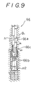
- Fig.9 shows an embodiment which the second modulator valve is modified.
- a plug 66b not as a part of a spool 66a, is provided, spring 66c is compressedly situated between the spool 66a and plug 66b.
- a traveling distance of the plug 66b is limited so that one end of the plug 66b contacts the valve body.
- the engine-brake control device is also applicable to the Ravigneaux type transmission unit.
- the modulator valves (65), (66) are hydraulically connected to the hydraulic servos (B1), or (B3) of brake which directly restrain certain element of the transmission gear mechanism (3), these modulator valves are controlled by the pressure control valve (linear solenoid valve) (S4), further, the pressure control valve (S4) is controlled by the control unit (C) which sends signals based on a vehicle running conditions. Because of this arrangement, the engine-brake is adequately actuated by the presice control of the pressure control valve (S4), so that the operation is easy and riding comfort is enhanced.
- modulator valves (66), (65) are controlled by the accumulator control valve (72) which is controlled by the pressure control valve (S4); accumulator back pressure control also functions without adding other control means.
Abstract
Description
- The present invention relates to a hydraulic control device for an automatic transmission used with engine, in particular to a hydraulic control device for an automatic transmission mounted on an automobile, in detail relates to an engine-brake control device to control hydraulic pressure of a brake hydraulic servo which is used for a brake directly restraining certain element of a shift gear mechanism.
- Conventionally, an automatic transmission works an engine-brake, at a second range (or S range) or a L range, by actuating a second coast brake (at 2nd speed) restraining front and rear sun gear, or by actuating a first & reverse brake (at 1st speed).
- Generally, hydraulic servos for the second-coast brake and the first & reverse brake are applied with a modulator pressure from a second-coast modulator valve or a low-coast modulator valve.
- As shown in the Japanese Laid Open Patent No. Sho-62-77245, with reference to an exhaust brake attached automatic transmission, an engine-brake control device which a line pressure is led to a low-coast modulator valve through a governor valve to vary a hydraulic pressure for the engine-brake according to a vehicle speed has been proposed.
- The above mentioned modulator valve reduces the line pressure and supplies it to the hydraulic servos of the second-coast brake and the first & reverse brake so that shift shock is reduced, however, the modulator valve, as shown in Fig.6 by dotted lines, the pressure is constantly reduced regardless of vehicle speed.
- Consequently, even if a manual valve is shifted to the second range or the L range at high speed, the engine-brake is not enoughly actuated because the second-coast brake or the first & reverse brake are not provided with enough torque capacities, on the contrary, when a vehicle is running at low speed, the brake torque is too large for a vehicle inertia force based on the low speed running, so that the engine-brake is too much actuated. Due to these motions, shifting operation is quite laborious, and a riding comfort is worse because operation of engine-brake delayed at high speed running which requires the operation of the engine-brake and works strongly at low speed running.
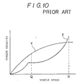
- With reference to the above mentioned device which varies the hydaulic pressure for the brake servo according to vehicle speed by the governor valve, as shown in Fig.10, a brake torque capacity X based on the governor valve is designed to be small at middle speed area Q because of a centrifugal force working on a governor weight, while the torque capacity is designed to be large at high speed area R. Subsequently, the brake torque capacity against necessary engine-brake torque capacity Y is not enough, so that a slip occurs. At the high speed area R, the brake torque capacity is too large against the necessary engine-brake torque capacity Y, so that sharp shift shock occurs.
- When a foot brake is applied with the engine-brake, in particualr, if the hydraulic pressure of engine-brake hydraulic servo is designed to be varied by a vehicle speed, driving wheels may be locked. Furthermore, when a vehicle runs on roads having low coeficient of friction such as snow roads, driving wheels may be slipped because the engine-brake torque capacity is too large.
- The present invention is purposed to solve the above mentioned disadvantages by controlling hydraulic pressure to a brake hydraulic servo through a pressure control valve (linear solenoid valve).
- The present invention, taking the above mentioned situation into consideration, provides, for example, as shown in Fig.1, the following provision: In a hydraulic control device for an automatic transmission including a brake directly restraining certain element of a shift gear mechanism, a hydraulic servo (B1) or (B3) to control the brake, shift valves (60), (61) to supply or drain the hydraulic pressure of the brake servo; modulator valves (66), (65) are situated in oil passages connected to the hydraulic servo (B1) or (B3), these modulator valves are controlled by a pressure control valve (S4) which is controlled by signals from a control unit (C) where the signals are produced based on a vehicle running conditions.
- More concretely, as shown in Fig.1 of the left side, a speed sensor (46) sends signals to the control unit (C), the unit (C) dispatches signals to the pressure control valve (S4) so that the hydraulic pressure of the hydraulic servo (B1) or (B3) is kept low when a vehicle speed is low while the hydraulic pressure of the servo is kept high when a vehicle speed is high.
- The control unit (C) receives signals from a brake sensor (47) which detects operation of a foot brake in addition to the signals from the sensor (46) so that when the foot brake is applied the pressure control valve (S4) is controlled to reduce the hydraulic pressure of the servo, which is varied according to a vehicle speed.
- The control unit (C) receives signals from a front wheel rotation detecting sensor (48) and a rear wheel rotation detecting sensor (49) and calculates the difference of rotation so that the pressure control valve (S4) keeps the hydraulic pressure of the servo low when rotation difference between the front and the rear wheel is large while the valve (S4) keeps the pressure of the servo high when rotation difference of the wheels is small.
- Furthermore, for example, the brakes are a second-coast brake (B1) which is actuated at the second speed of other than D range, and a first & reverse brake (B3) which is actuated at the first speed. To the second-coast brake hydraulic servo (B1), a line pressure (p) is applied from a port (b) from which the line pressure is applied at the second range and L range of a manual valve (51) through ports (b1), (f) of a 2-3 shift valve (61); ports (f1), (g) of a 1-2 shift valve (60); ports (g1), l(h) of a second-coast modulator valve (66). Draining pressure form the servo (B1) is drained from a check ball (91) without passing through the modulator valve (66). On the other hand, to the first & reverse brake hydraulic servo (B3), a line pressure (p) is applied from a port (c) from which the line pressure is applied at the L range of the manual valve (51) through ports (c1), (i) of the 2-3 shift valve (61); ports (i1), (j) of the low-coast modulator valve (65); ports (j1), (k) of the 1-2 shift valve (60); and a check ball (90).
- The second-coast modulator valve (66) has a control chamber (m2) where control hydraulic pressure from a port (m) of an accumulator control valve (72) is applied, and the low-coast modulator valve (65) has a control chamber (m3) where control hydraulic pressure from a port (m) of the accumulator control valve (72) is applied. The accumulator control valve (72) has a port (n1) where hydraulic pressure from ports (n), (n) of the pressure control valve (S4) which is controlled by electric signals of the control unit (C) which receives the signals from the speed sensor (46), the brake sensor (47), the front and rear wheel rotation sensors (48), (49) is applied. Consequently, regulated pressure is applied to the port (n1) so that the line pressure applied to a port (p2) is regulated and such regulated pressure is taken out from port (m) of the accumulator control valve (72). A port (o) of the pressure control valve (S4) is applied with reduced pressure from a solenoid modulator valve(73).
- Based on the above structure, when engine-brake is actuated by the brake (B1) or (B3), the regulated hydraulic pressure through the modulator valve (66) or (65) which is controlled by the pressure control valve (S4) is applied to the brake hydraulic servo. At this time, the solenoid valve (S4) is controlled by signals based on a vehicle running condition such as the speed sensor (46), accordingly high hydraulic pressure is applied when a vehicle runs at high speed, while low hydraulic pressure is applied when a vehicle rung at low speed. Because of this procedure, the engine-brake force is adequately controlled according to a vehicle speed. Furthermore, for example, the following provisions are also possible: due to the signal of the brake sensor (47), the hydraulic pressure according to a vehicle speed is kept low when the foot brake is applied. And due to the signals of the front and rear wheel rotation sensors, the control unit (C) calculates rotation difference, and the engine-brake force is kept low when the rotation difference between the front and rear wheels is large.
- More concretely, when the engine-brake is applied at the second speed condition by shifting the manual valve (51) to the second range, the line pressure from the port (b) of the manual valve (51) is applied to the port (g1) of the second-coast modulator valve (66) through the ports (b1), (f) of the 2-3 shift valve (61); the ports (f1), (g) of the 1-2 shift valve (60). Moreover, the hydraulic pressure is regulated based on the con trol pressure of the control chamber (m2), then the regulated pressure is applied to the second-coast brake hydraulic servo B1). At this time, the pressure control valve (S4) is controlled by the signals from the control unit (C) where signal of each sensor (46), (47), (48), (49) are sent. Then hydraulic pressure applied to the port (o) is regulated and taken out from the ports (n), (n). Subsequently, the pressure from the ports (n), (n) is applied to the port (n1) of the accumulator control valve (72) where the line pressure of the port (p2) is regulated by the line pressure (p1) and the hydraulic pressure at the port (n1), thus the regulated hydraulic pressure is applied from the port (m) of the accumulator control valve (72) to the control chamber (m2) of the second-coast modulator valve (66). Due to the above operations, the engine-brake hydraulic pressure is generated, as shown in Fig.6, having three areas: (D) - high constant pressure for high speed condition which is more than certain speed; (E) - hydraulic pressure is reduced proportional to a vehicle speed; (F) - low constant pressure for low speed condition. Or the engine-brake hydraulic pressure (G) which is proportional to a vehicle speed is generated.
- When the engine-brake is applied at the first speed by shifting the manual valve (51) to the L range, the line pressure is applied from the port (c) of the manual valve (51) to the port (i1) of the low-coast modulator valve (65) through the ports (c1), j) of the 2-3 shift valve (65). In the valve (65), the line pressure is regulated based on the control pressure of the control chamber (m3) and applied to the first & reverse brake hydraulic servo (B3). At this time, as stated before, the control pressure is generated by the pressure control valve (S4) and the accumulator control valve (72), then the engine-brake hydraulic pressure is also generated as shown in Fig.6 by continuous line and dotted lines.
- The means to control the modulator valve is not limited to the above accumulator control valve (72). It is of course possible to connect a regulated pressure generating means such as a linear solenoid valve directly to a control chamber of the modulator valve.
- Incidentally, the reference numerals in the prentheses are used only for reference with the drawings and do not define the invention. The same number may be named differently in the following description and in the previous descriptrion in which broader concepts are adopted.
- In the drawings:
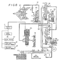
- Fig.1 is a hydraulic circuit diagram of a main part of a engine-brake control device for an automatic transmission, which relates to the present invention;
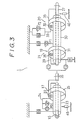
- Fig.2 is a total cross sectional view of the automatic transmission to which the present invention is applied;
- Fig.3 is a schematic representation of the automatic transmission;
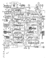
- Fig.4 is a hydraulic circuit diagram of the automatic transmission;
- Fig.5 is a table of operation of solenoid valves, clutches, brakes and one-way clutches at each shifting position;
- Fig.6 is a graphical representation showing an engine-brake hydraulic pressure vs. vehicle speed;
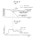
- Fig.7 is a graphical representation of engine-brake skid control;
- Fig.7 (a) is a graphical representation showing time vs. front and rear wheels rotation speed;
- Fig.7 (b) is a graphical representation showing time vs. hydraulic pressure of a hydraulic servo;
- Fig.8 is a hydraulic circuit diagram which is partially modified from the original embodiment;
- Fig.9 is a cross sectional view of a second-coast modulator valve which is partially modified;
- Fig.10 is a graphical representation of engine-brake characteristic by a governor valve.
- The present invention will now be explained along with the drawings.
- An
automatic transmission 1, as shown in Fig.2 and 3, has atorque converter 2, a planetary transmission gear mechanismn3 and ahydraulic control device 5 which are housed in aconverter housing 6, a transmission case 7, anextension housing 9, avalve body 10 and anoil pan 11. Thetorque converter 2 has a lock-up clutch 12, so that rotation of aninput member 13 is transmitted to aninput shaft 15 of thetransmission gear mechanism 3 through hydraulic flow of thetorque converter 2 or the lock-up clutch 12. Theshift gear mechanism 3 comprises amain transmission unit 21 including an over-driveplanetary gear unit 17, a frontplanetary gear unit 19 and a rearplanetary gear unit 20. The over-driveplanetary gear unit 17 comprises aplanetary pinion 22, acarrier 24 which is directly connected to theinput shaft 15 and supports thepinion 22, asun gear 23 which encloses theinput shaft 15, and aring gear 25 which is connected to aninput shaft 26 of themain transmission mechanism 21. An over-drive direct clutch C0 and a one-way clutch F0 are situated between thecarrier 24 and thesun gear 23, and an over- drive brake B0 is situated between thesun gear 23 and the case 7. The frontplanetary gear unit 19 comprises aplanetary pinion 28, acarrier 29 which is directly connected to anoutput shaft 27 and supports thepinion 28, asun gear 30a which encloses theoutput shaft 27 and is constituted integrally with asun gear 30b of the rearplanetary gear unit 20, and aring gear 31 which is connected to theinput shaft 26 through a forward clutch C1. A direct clutch C2 is situated between theinput shaft 26 and thesun gear 30, a second-coast brake B1 composed of a band brake is situated between thesun gear 30 and the case 7, a one-way cltuch F1 and a second brake B2 are radially situated between thesun gear 30 and the case 7. The rearplanetary gear unit 20 comprises aplanetary pinion 32, acarrier 33 which supports thepinion 32, asun gear 30b, and aring gear 35 which directly connects to theoutput shaft 27. A first & reverse brake B3 and a one-way clutch F2 are situated radially between thecarrier 33 and the case 7. Incidentally 36 in Fig.2 is an oil pump. - And, as shown in Fig.2, with regard to the over-drive
planetary gear unit 17, the one-way clutch F0 is situated between a boss 23a of thesun gear 23 and asleeve 24a of thecarrier 24. A flange member 40 which constitutes a cylinder is extended from the bass 23a. The flange member 40 encloses a piston member 41 to form an hydraulic actuator of the clutch C0, the over-drive direct clutch C0 is situated between thesleeve 24a and an inner surface of the flange 40. The over-drive brake B0 is situated between an outer surface of the flange 40 and the case 7. Furthermore, abrim 42 is fixed on a peripheral part of the flange 40. Anon-contacting type sensor 45 such as employing light or magnetic and the like is situated on the case 7 so that thesensor 45 faces plural through holes or slits which are formed on thebrim 42. Thesensor 45 is situated to detect rotation speed of the clutch C0, in other words, to detect rotation speed of thebrim 42 which rotates together with theinput member 15 at the first, second and third speeds. - While, a
speed sensor 46 which detects vehicle speed is situated in theextension case 9. Electric signals of thesensor - Next, a
hydraulic control device 5 is explained along with Fig.4. - C0, C1 and C2 are hydraulic servos for each clutch, B0, B1, B2 and B3 are hydraulic servos for each brake, and 2 is a torque converter, 36 is an oil pump. 51 is a manual valve where a line pressure port p is connected to ports a, b, c and d which corresponds to ranges of R, P, N, D, S and L, as shown in the table in Fig.4. 52 is a primary regulator valve, 53 is a throttle valve, 55 is a secondary regulator valve, 56 is a lock-up control valve, 57 is a lock-up relay valve, 58 is a solenoid relay valve, 59 is a cutback valve. 60 is a 1-2 shift valve, 61 is a 2-3 shift valve, 62 is a 3-4 shift valve, 63 is a reverse inhibit valve, 65 is a low-coast modulator valve, 66 is a second-coast modulator valve. 67 is an accumulator for the clutch C0, 70 is an accumulator for the clutch C2, 71 is an accumulator for the brake B2. 72 is an accumulator control valve which regulates hydraulic pressure applied to back
pressure chamber accumulator 69, 70 and 71, and controls the low-coast modulator valve 65 and the second-coast modulator valve 66. S1, S2 and S3 are solenoid valves to control theshift valves solenoid regulator valve 73, and the regulated pressure is sent applied to theaccumulator control valve 72. - Next, an engine-brake control device which is a main part of the present invention is explained along with Fig.1.
- The engine-brake control device is to control a supply hydraulic pressure to the second-coast brake hydraulic servo B1 which operates at the second speed of the second range and the L range, and to the first & reverse brake hydraulic servo B3 which operates at the first speed of the L range. And this engine-brake control device has; the second-
coast modulator valve 66 and the low-coast modulator valve 65 which are situated in oil passages to the servos; theaccumulator control valve 72 controlling these modulator valves; the linear solenoid valve S4 and thesolenoid modulator valve 73. - The port b, in the
manual valve 51, where the line pressure is applied at the second range of themanual valve 51 is connecte to the port b1 of the 2-3shift valve 61. The 2-3shift valve 61 is in an upper-half position (which means the position of spool depicted in the right side of the spool in Fig.1) at the second speed, so that the port b1 and the port f are through. Furthermore, the port f is connected to the port f1 of the 1-2shift valve 60. The 1-2shift valve 60 is in a left-half position which means the position of spool depicted in the left side of the spool in Fig.1) at the second speed, so that the port f1 and the port g are through. The port g is connected to the port g1 of thesecond modulator valve 66. The hydraulic pressure at the port g1 is regulated by control pressure in a control chamber m2, and the regulated pressure is taken from the port h to the second-coast brake hydraulic servo B1. The drain pressure from the servo B1 is led to the port g of the 1-2shift valve 60 through thecheck ball 91, and drained from the drain port EX. - The port c, in the
manual valve 51, where the line pressure p is applied at the L range of themanual valve 51 is connected to the port c1 of the 2-3shift valve 61. At the first speed, the line pressure from the port c is applied to the lower chamber c2, so that thevalve 61 is in the right-half position, thus the port c1 and the i are through. The port i is connected to the port i1 of the low-coast modulator valve 65. The pressure at the port i1 is regulated by control pressure of a control chamber m3, and this regulated pressure is taken from the port j to the port j1 of the 1-2shift valve 60. At the first speed, thevalve 60 is in the right-half position, so that the port j1 and the port k are through. The hydraulic pressure from the port k is applied to the first & reverse brake hydraulic servo B3 through acheck ball 90. Incidentally thecheck ball 90 has a port d1 which is connected to the port d of themanual valve 51, which the line pressure is applied at the reverse range, and a port k1 which is connected to the port k. By the hydraulic pressure applied at one of these ports d1, k1, aball 90b in asleeve 90a is moved so that the pressure is applied to the servo B3 from the port q. - On the other hand, the
accumulator control valve 72 has; a port p2 which the line pressure is applied; a first control chamber p1 by which the line pressure is applied on the top of spool; a second control chamber n1 which the control pressure from the linear solenoid valve S4 is applied; a regulating port m which regulates the line pressure of the port p2, and connects the control chamber m2, m3 of the second-coast modulator valve 66 and the low-coast modulator valve 66 respectively; a feedback chamber m1 whose hydraulic pressure works together with the pressure of the control chamber n1 and pressing force of the spring 72a against the line pressure off the control chamber p1. The linear solenoid valve S4 is controlled by electric signals of the control unit C which is based on the signals ofspeed sensor 46,brake sensor 47, frontwheel rotation sensor 48 and rearwheel rotation sensor 49. The port o of the valve S4 is applied with pressure which is a reduced line pressure by thesolenoid modulator valve 73, then the reduced line pressure is regulated in the valve S4 and is output to the ports n, n. The hydraulic pressure from the ports n, n is applied to the control chamber n1 of theaccumulator control valve 72. - In addition to the above, as shown in Fig.4, the pressure from the port m of the
accumulator control valve 72 is applied to theback pressure chamber modulator valves cutback valve 59 so that cutback operation by thecutback valve 59 is stopped when the second-coast brake B1 is actuated. - The operation of embodiment will now be explained.
- The solenoid valves S1, S2 and S3; the clutches C0, C1 and C2; the brakes B0, B1, B2 and B3; the one-way clutches F0, F1 and F2; are operated at the positions of P, R, R(speed is more than 7 km/h), N, D, 2 and L ranges, as shown in Fig.5.
- In other words, at the first speed of the D or 2 range; the solenoid valve S1 is ON, so that the over-drive direct clutch C0, the one-way clutch F0, F2 and the forward clutch C1 are engaged, other elements are all released. Accordingly, all elements of the over-drive
planetary gear unit 17 rotates together through the clutch C0 and the one-way clutch F0, thus rotation of theinput shaft 15 is transmitted theinput shaft 26 of themain transmission unit 21 without reducing rotation speed. At themain transmission unit 21, rotation of theinput shaft 26 is transmitted to thering gear 31 of the frontplanetary gear unit 19, and transmitted to thecarrier 29 and theoutput shaft 27 which is integrally connected with thecarrier 29. At the same time, the rotation is transmitted to thecarrier 33 of the rearplanetary gear unit 20, and thecarrier 33 is provided with torque in the left rotational direction, however thecarrier 33 is restrained by the one-way clutch F2, thus theplanetary pinion 32 rotates, and this rotation is transmitted to thering gear 35 which is integrally connected with theoutput shaft 27. - At the second speed of the D range; the solenoid valve S2 is ON in addition to the solenoid valve S1. The over-drive direct clutch C0, the one-way clutch F0, the forward clutch C1, the one-way clutch F1 and the second brake B2 are engaged, and other elements are all released. Accordingly, the over-drive
planetary gear 17 is still kept under the direct operating condition, the rotation of theinput shaft 15 is transmitted to theinput shaft 26 without reducing rotation speed. At themain transmission unit 21, rotation of theinput shaft 26 is transmitted to thering gear 31 through the forward clutch C1, and thesun gear 30 is provided with torque in the left rotational direction through thepinion 28. However, thesun gear 30 is restrained in the left rotational direction by the operation of the one-way clutch F1 because of engagement of the brake B2, consequently, theplanetary pinion 28 rotates and thecarrier 29 rotates. Then the rotation of thecarrier 29 is directly transmitted to theoutput shaft 27, namely the rotation is transmitted only through thefront gear unit 19 to theoutput shaft 27. - At this moment, when friction plates of the second brake B2 start to contact by application of hydraulic pressure to the B2 hydraulic servo, the output torque varies, as a result, rotation speed of the flange 40 which rotates together with the
input shaft 15 also varies. The varied rotation is detected by thesensor 45, then the solenoid valve S4 is controlled by the electric signals of the control unit C based on the signals of thesensor 45. Consequently, hydraulic pressure applied from thesolenoid modulator valve 73 is regulated in the solenoid valve S4 and such regulated pressure is taken from the ports n, n as a certain control hydraulic pressure the certain control pressure is applied to the port n1 of theaccumulator control valve 72. Thecontrol valve 72 is under the right-half position (Fig.1) by hydraulic pressure being applied to the first control chamber p1 through an orifice, and the line pressure applied from the port p2 is taken out from the port m to apply to theback pressure chamber 71a of the accumulator 71, from the above state of thecontrol valve 72, the control pressure from the port m works to a bulged section of the spool, and the pressure, with the pressing force of the spring 72a, moves the spool against the line pressure of the first control chamber p1. Consequently the line pressure of the port p2 is reduced in accordance with the control pressure and taken out from the port m. The reduced pressure works from the feedback port m1 to a lower part of thespool 72, at the same time the reduced pressure is applied to the back pressure chamber 71b of the accumulator 71. Because of these motions, the accumulator back pressure is reduced by certain volume and certain duration of time. Furthermore, after certain time, the accumulator back pressure is gradually reduced based on the control pressure of from the linear solenoid valve S4, the output torque is smoothly varies. Thus, when shifting from the first speed to the second, shift-shock caused by engaging the second brake B2 is reduced, so that shift-up operation is conducted smoothly. - At the third speed of the D or second range; the solenoid valve S1 is OFF, the over-drive direct clutch C0, the one-way clutch F0, the forward clutch C1, the direct clutch C2 and the second brake B2 are engaged, and other elements are all released. As a result, the over-drive
planetary gear unit 17 is under the direct operating condition, and in themaim transmission mechanism 21, the elements of the frontplanetary gear unit 19 rotate together because the clutch C1 and C2 are engaged, thus rotation of theinput shaft 26 is transmitted to theoutput shaft 27 without reducing rotation speed. - The 2-3
shift valve 61 is switched due to the solenoid valve S4 being OFF, the direct clutch C2 is engaged, at this moment, as same as the B2 accumulator 71, certain hydraulic pressure is applied to the back pressure chamber 70a of the C2 accumulator 70, so that shift shock is reduced when shifting from the second to the third speed as same as the shifting from the first to the second speed. - At the fourth speed of the D range, or the highest shift stage; the solenoid valve S2 is also OFF, the forward clutch C1, the direct clutch C2, and the second brake B2 are engaged. The
main transmission mechanism 21, as same as the third speed, is under the direct operating condition, while at the over-driveplanetary gear unit 17, the direct clutch C0 is released and the over-drive brake B0 is engaged. Accordingly, thesun gear 23 is locked by the brake B0, theplanetary pinion 22 rotates with thecarrier 24 which also rotates, then rotation is transmitted to thering gear 25 as an over-drive rotation, the over-drive rotation is transmitted to theinput shaft 26 of themain transmission mechanism 21 which is under the direct operating condition. - At this time, because of the release of the direct clutch C0 and the engagement of the brake B0, rotation of the
brim 42 which is integrally connected to the flange 40 connected to thesun gear 23 is restrained, this state is detected by thesensor 45. Certain hydraulic pressure is applied to theback pressure chamber 69a of theB0 accumulator 69, so that hydraulic pressure for the brake B0 is controlled. On the other hand, in the direct clutch hydraulic servo C0, pressure rises comparatively quick because of theaccumulator 67 without back pressure control, so that the clutch C0 is released eariler than the brake B0, however thecarrier 24 is still under the control of the one-way clutch F0 regardless of the release of the clutch C0. As a result, The shifting operation from the third speed to the fourth is performed by the engagement of the brake B0 and the release of the clutch C0, shift shock is reduced by the control of theB0 accumulator 69. - When down shifting from the fourth to the third speed; the over-drive direct clutch C0 is engaged and the over-drive brake B0 is released. When down shifting from the third to the second speed, the direct clutch C2 is released, furthermore when shifting down from the second to the first speed, the second brake B2 is released.
- Under the above situation, the linear solenoid valve S4 is controlled by the electric signals from the control unit C based on the
speed sensor 45, thus the accumulator back pressure working on theback pressure chambers 69a of theB0 accumulator 69, 70a of the C2 accumulator and 71a of the B2 accumulator 71 are reduced by certain timing and certain time. Due to these motions, shift shock is reduced when down shifting as same as up-shifting, so that shifting operation is performed smoothly. - When the
manual valve 51 is shifted to the second range; the first and third speeds are as same as those of the D range. When the second speed, the second-coast brake B1 is engaged in addition to the forward clutch C1, the over-drive direct clutch C0 and the second brake B2, so that thesun gear 30 of themain transmission mechanism 21 is restrained to actuate the engine-brake. In other words, the line pressure from the port b which applies the line pressure at the second range of themanual valve 51 is applied to the port b1 of the 2-3shift valve 61, the port b1 and f are through based on the right-half position of theshift valve 61, and from the port f, the line pressure is applied to the port g1 of the second-coast modulator valve 66 through the ports f1, g of the 1-2shift valve 60. The control unit C based on thespeed sensor 46 sends signals to the linear solenoid valve S4, the valve S4 regulates the hydraulic pressure at the port o to be a pressure corresponding to a vehicle speed. The regulated pressure is taken out from the ports n, n to the second control chamber n1 of theaccumulator control valve 72. Due to the application of hydraulic pressure to the chamber n1, from the condition that thevalve 72 is under the right-half position and the line pressure at the port p2 is through to the port m; the control pressure of the second control chamber n1, pressing force of the spring 72a situated at lower part of the spool, and the feedback pressure of the third control chamber m1 work together against the line pressure of the first control chamber p1, so that the line pressure of the port p2 is reduced by certain volume and is taken out from the port m. The hydraulic pressure of the port m is applied to the control chamber m2 of the second-coast valve 66, and the hydraulic pressure from the port h is regulated, for example as shown in Fig.6 of chain line or full line, and is applied to the second-coast hydraulic servo B1. In the case that characteristic indicated by chain line is employed; when a vehicle runs at comparatively high speed, high hydraulic pressure such as the line pressure and the like is applied to the control chamber m2 of themodulator valve 66, so that the valve is at the right-half position, thus high and constant pressure works (refer to the area D of Fig.6) and the second brake B1 actuates the engine-brake with large torque capacity. When a vehicle slows down its speed below certain level, application of hydraulic pressure to thehydraulic servo B 1 is also reduced in proportional to the slow down of vehicle speed (refer to the area E of Fig.6), the second coast brake B2 actuates the engine-brake with reducing torque capacity according to a vehicle speed. When a vehicle further slows down its speed below another certain level, application of hydraulic pressure to the servo B1 is low and constant (refer to the area F of Fig.6), the brake B1 actuates the engine-brake smoothly with small torque capacity. - Incidentally, by the operation of the
accumulator control valve 72 when the engine-brake is actuated, certain hydraulic pressure is applied to theback pressure chamber 71a of the B2 accumulator 71, however, the application of pressure provides no significant effects against shift shocks. - At the second speed of the L range; it is same as the second range of the second range. At the first speed; the first & reverse brake B3 is engaged in addition to the forward clutch C1 and the over-drive direct clutch C0, so that the
carrier 33 of the rearplanetary gear unit 20 is restrained, thus, the engine-brake is acutated. Namely, the line pressure at the port c which the line pressure is applied at the L range of the manual valve is applied to the port c1 of the 2-3shift valve 61. And thevalve 61 is under the right-half position by the line pressure of the chamber c2 at the first speed, so that the port c1 and i are through, from the port i, the line pressure is applied to the port i1 of the low-coast modulator valve 65. Themodulator valve 65, as stated before, is regulated by the linear solenoid valve S4 and the control pressure from the port m of theaccumulator control valve 72. The regulated pressure from the port j of thevalve 65 is applied to the port k1 of thecheck ball 90 through the ports j1 and k of the 1-2shift valve 60 which is under the right-half position. Furthermore, the pressure is applied from the port q to the first & reverse brake hydraulic servo B3. At this time, by the control pressure based on thespeed sensor 46, the regulated pressure from the port j of themodulator valve 65 is applied to the servo B3, for example as shown in the full line or chain line of Fig.6 In the case that the characteristic shown by the full line, the pressure which is proportional to the slow down of vehicle speed is applied to the servo B3, then, the brake B3 actuates the engine-brake with large torque capacity when running at high speed, while, the brake B3 actuates the engine-brake with gradually reducing torque capacity corresponding to reduction of inertial force which is reduced according to the slow down of vehicle speed. - It is possible to add the signals of the
brake sensor 47 to that of thespeed sensor 46 by input signals of thesensor 47 to the control unit C. Namely, as shown by G′, E′ and D′ in Fig.6, in the case that the foot brake is actuated, the engine-brake pressure is designed to be low to prevent locking of wheels. - It is also possible to control the engine-brake pressure based on rotation difference of the front and rear wheels by calculating the difference in the control unit C to which the signals from the front
wheel rotation sensor 48 and the rearwheel rotation sensor 49 are designed to be input. Namely, as shown in (a), (b) of Fig.7, in the case that the engine-brake is actuated on a road having low coeficient of friction such as snow road, conventionally, though driving wheel slips, skid state occurs due to a constant servo pressure, on the other hand, in the present embodiment, when driving wheel slips and caused rotational difference Δ N between the driving wheel and the following wheels, then servo pressure is reduced by certain volume to reduce the engine-brake torque working to the driving wheels, thus occurrence of slip of the driving wheels is prevented. - At the reverse range; the over-drive clutch C0, the one-way clutch F0, the direct clutch C2 and the first & reverse brake B3 are engaged, and other elements are all released. Accordingly the over-drive
planetary gear unit 17 is under the direct operating condition, and in themain transmission mechanism 21, rotation of theinput shaft 26 is directly transmitted to thesun gear 30 through the clutch C2, and as thecarrier 33 is restrained by the brake B3, the rotation of thesun gear 30 is transmitted to thering gear 35 as reverse rotation through thepinion 32 which rotates, thus theoutput shaft 27 rotates reversely. - When the
manual valve 51 is shifted to the R range, if a vehicle speed is over a certain level for example 7 km/h, the solenoid valve S2 is ON, so the direct clutch C2 is released, as a result, no reverse running condition occurs. - Next, an embodiment which is partially modified from the above stated embodiment is explained along with Fig.8.
- In this embodiment, regulated hydraulic pressure from the linear solenoid valve S4 is invariably applied without an accumulator control valve. Certain hydraulic pressure is invariably applied to the control chambers m2, m3 of the modulator valves from the port n, n of the linear solenoid valve S4. Based on the
speed sensor 46 which detects speed change, the solenoid valve S4 is controlled to regulate the control pressure, and the regulated hydraulic pressure which is reduced by certain volume is applied to the control chamber m2 of the second-coast modulator valve 66 and the control chamber m3 of the low-coast modulator valve 65. - Furthermore, Fig.9 shows an embodiment which the second modulator valve is modified.
- On the
second modulator valve 66 shown in Fig.9, aplug 66b, not as a part of aspool 66a, is provided,spring 66c is compressedly situated between thespool 66a and plug 66b. A traveling distance of theplug 66b is limited so that one end of theplug 66b contacts the valve body. - Consequently, even if the control pressure led to the control chamber m2 becomes high, the end of the
plug 66b contacts thevalve body 10, so that the regulated pressure from the port h, or the hydraulic pressure applied to the second-coast brake hydraulic pressure servo B1 is not reduced any more. By this operation, the reduced and constant brake pressure (F) shown in Fig.6 is easily obtained. - In the above embodiments, explanation is stated about an automatic transmission having the over-drive
planetary gear unit 17, or sub transmission unit, in addition to this arrangement, the engine-brake control device is also applicable to an automatic transmission without the above sub transmission unit. - In the above embodiment, explanation is stated about the Simpson type transmission unit, and not limited to this type, the engine-brake control device is also applicable to the Ravigneaux type transmission unit.
- As explained, the modulator valves (65), (66) are hydraulically connected to the hydraulic servos (B1), or (B3) of brake which directly restrain certain element of the transmission gear mechanism (3), these modulator valves are controlled by the pressure control valve (linear solenoid valve) (S4), further, the pressure control valve (S4) is controlled by the control unit (C) which sends signals based on a vehicle running conditions. Because of this arrangement, the engine-brake is adequately actuated by the presice control of the pressure control valve (S4), so that the operation is easy and riding comfort is enhanced.
- In the case that the hydraulic pressure of servos (B1), (B3) are controlled in accordance with vehicle speed based on the speed sensor (46) (refer to the lines E, G in Fig.6); an adequate engine-brake force is provided when vehicle inertia force is reduced with slow down of vehicle speed, so that the engine-brake force is not changed sharply.
- Furthermore, under the provision that signal is sent from the foot brake sensor (47) to the control unit (C), when the engine-brake is acutated, the hydraulic servo pressure which varies in accordance with vehicle speed is set to be low, even when the foot brake and the engine-brake are actuated at the same time, locking of wheels is prevented.
- In the case that the signals of the front and rear wheel rotation sensors (48), (49) are sent to the control unit (C) to control the solenoid valve (S4), occurrence of slip is prevented when the engine-brake is actuated. In particular, in the case hydraulic pressure of servos are set to be low when rotational difference between front and rear wheels is small, while hydraulic pressure of servos are set to be high when rotational difference is large; skid is prevented when the engine-brake is actuated on the roads having low coeficient of friction.
- Furthermore, in the case that the modulator valves (66), (65) are controlled by the accumulator control valve (72) which is controlled by the pressure control valve (S4); accumulator back pressure control also functions without adding other control means.
Claims (12)
a modulator valve which is situated in an oil passage to said hydraulic servo,
a pressure control valve controlled by a signal which is in response to vehicle running conditions, from a control unit,
whereby said modulator valve is controlled by a hydraulic pressure which is controlled by said pressure control valve.
Applications Claiming Priority (4)
| Application Number | Priority Date | Filing Date | Title |
|---|---|---|---|
| JP37882/88 | 1988-02-20 | ||
| JP63037882A JP2911120B2 (en) | 1988-02-20 | 1988-02-20 | Hydraulic control device for automatic transmission |
| JP70157/88 | 1988-03-23 | ||
| JP07015788A JP3287560B2 (en) | 1988-03-23 | 1988-03-23 | Engine brake control device for automatic transmission |
Publications (3)
| Publication Number | Publication Date |
|---|---|
| EP0330409A2 true EP0330409A2 (en) | 1989-08-30 |
| EP0330409A3 EP0330409A3 (en) | 1990-09-05 |
| EP0330409B1 EP0330409B1 (en) | 1995-04-26 |
Family
ID=26377039
Family Applications (1)
| Application Number | Title | Priority Date | Filing Date |
|---|---|---|---|
| EP89301634A Expired - Lifetime EP0330409B1 (en) | 1988-02-20 | 1989-02-20 | An engine brake control device for an automatic transmission |
Country Status (3)
| Country | Link |
|---|---|
| US (1) | US4991464A (en) |
| EP (1) | EP0330409B1 (en) |
| DE (1) | DE68922329T2 (en) |
Cited By (5)
| Publication number | Priority date | Publication date | Assignee | Title |
|---|---|---|---|---|
| EP0707164A2 (en) * | 1994-10-14 | 1996-04-17 | Ford Motor Company Limited | Shift control system for a multiple ratio automatic transmission |
| EP0811794A2 (en) * | 1996-06-06 | 1997-12-10 | Aisin Aw Co., Ltd. | Control mechanism for automatic transmission |
| EP0813004A2 (en) * | 1996-06-11 | 1997-12-17 | Aisin Aw Co., Ltd. | Speed change control system for automatic transmission |
| EP0715100A3 (en) * | 1994-12-02 | 1998-04-01 | Aisin Aw Co., Ltd. | Oil pressure controller of automatic transmission |
| EP0825366A3 (en) * | 1996-08-23 | 1998-07-22 | Ford Motor Company Limited | Swap-shift control system for a multiple ratio transmission |
Families Citing this family (4)
| Publication number | Priority date | Publication date | Assignee | Title |
|---|---|---|---|---|
| DE4235866A1 (en) * | 1991-10-24 | 1993-07-01 | Aisin Aw Co | Hydraulic control system for automatic vehicle transmission - has split hydraulic servo systems for rapid response gear changing, two servos operating one gear, and third operating second gear |
| JP2878964B2 (en) * | 1994-05-02 | 1999-04-05 | アイシン・エィ・ダブリュ株式会社 | Control method and control device for automatic transmission |
| JP3374168B2 (en) * | 1994-12-01 | 2003-02-04 | ジヤトコ株式会社 | Transmission control device for automatic transmission |
| JP3688250B2 (en) * | 2002-04-17 | 2005-08-24 | トヨタ自動車株式会社 | Control device and control method for automatic transmission |
Citations (3)
| Publication number | Priority date | Publication date | Assignee | Title |
|---|---|---|---|---|
| EP0214467A2 (en) * | 1985-08-05 | 1987-03-18 | Nissan Motor Co., Ltd. | Downshift timing and engine brake control for automatic transmission |
| JPH06217452A (en) * | 1993-01-13 | 1994-08-05 | Nec Corp | Protective circuit for communication |
| JPH06277245A (en) * | 1993-01-14 | 1994-10-04 | E R Squibb & Sons Inc | Artificial anus bag with multi-stage filter |
Family Cites Families (8)
| Publication number | Priority date | Publication date | Assignee | Title |
|---|---|---|---|---|
| JPS5112777B1 (en) * | 1970-04-04 | 1976-04-22 | ||
| JPS534194B1 (en) * | 1971-04-10 | 1978-02-15 | ||
| JPS4926929A (en) * | 1972-07-12 | 1974-03-09 | ||
| US4350234A (en) * | 1979-02-02 | 1982-09-21 | Nissan Motor Co., Ltd. | Automatic transmission system provided with a function of engine brake |
| US4262783A (en) * | 1979-07-31 | 1981-04-21 | Scarrott Gordon G | Vehicle propulsion control systems |
| US4690017A (en) * | 1985-07-01 | 1987-09-01 | Toyota Jidosha Kabushiki Kaisha | Shift control system of automatic transmission |
| JPS6217452A (en) * | 1985-07-15 | 1987-01-26 | Nissan Motor Co Ltd | Device for controlling engine brake for automatic transmission |
| JPH0717166B2 (en) * | 1985-09-30 | 1995-03-01 | アイシン精機株式会社 | Automatic transmission |
-
1989
- 1989-02-20 DE DE68922329T patent/DE68922329T2/en not_active Expired - Lifetime
- 1989-02-20 EP EP89301634A patent/EP0330409B1/en not_active Expired - Lifetime
- 1989-02-21 US US07/313,234 patent/US4991464A/en not_active Expired - Lifetime
Patent Citations (3)
| Publication number | Priority date | Publication date | Assignee | Title |
|---|---|---|---|---|
| EP0214467A2 (en) * | 1985-08-05 | 1987-03-18 | Nissan Motor Co., Ltd. | Downshift timing and engine brake control for automatic transmission |
| JPH06217452A (en) * | 1993-01-13 | 1994-08-05 | Nec Corp | Protective circuit for communication |
| JPH06277245A (en) * | 1993-01-14 | 1994-10-04 | E R Squibb & Sons Inc | Artificial anus bag with multi-stage filter |
Cited By (9)
| Publication number | Priority date | Publication date | Assignee | Title |
|---|---|---|---|---|
| EP0707164A2 (en) * | 1994-10-14 | 1996-04-17 | Ford Motor Company Limited | Shift control system for a multiple ratio automatic transmission |
| EP0707164A3 (en) * | 1994-10-14 | 1997-09-17 | Ford Motor Co | Shift control system for a multiple ratio automatic transmission |
| EP0715100A3 (en) * | 1994-12-02 | 1998-04-01 | Aisin Aw Co., Ltd. | Oil pressure controller of automatic transmission |
| EP0811794A2 (en) * | 1996-06-06 | 1997-12-10 | Aisin Aw Co., Ltd. | Control mechanism for automatic transmission |
| EP0811794A3 (en) * | 1996-06-06 | 1998-09-02 | Aisin Aw Co., Ltd. | Control mechanism for automatic transmission |
| EP0813004A2 (en) * | 1996-06-11 | 1997-12-17 | Aisin Aw Co., Ltd. | Speed change control system for automatic transmission |
| EP0813004A3 (en) * | 1996-06-11 | 1998-06-24 | Aisin Aw Co., Ltd. | Speed change control system for automatic transmission |
| US5833573A (en) * | 1996-06-11 | 1998-11-10 | Aisin Aw Co., Ltd. | Speed change control system for automatic transmission |
| EP0825366A3 (en) * | 1996-08-23 | 1998-07-22 | Ford Motor Company Limited | Swap-shift control system for a multiple ratio transmission |
Also Published As
| Publication number | Publication date |
|---|---|
| DE68922329T2 (en) | 1995-09-28 |
| EP0330409A3 (en) | 1990-09-05 |
| DE68922329D1 (en) | 1995-06-01 |
| EP0330409B1 (en) | 1995-04-26 |
| US4991464A (en) | 1991-02-12 |
Similar Documents
| Publication | Publication Date | Title |
|---|---|---|
| US5873802A (en) | Vehicle control apparatus having means for preventing interference between transmission controls by running stability control means and manual shift control means | |
| US4513639A (en) | Creeping preventing apparatus in automatic transmission for vehicle | |
| US4519273A (en) | Automatic transmission for vehicles | |
| US4476747A (en) | Timing control valve in automatic transmission control apparatus | |
| US3688607A (en) | Transmission and control | |
| US5875680A (en) | Automatic forward/reverse gear change system having a main clutch disengaged and main vehicle brake engaged during a shuttle shift | |
| US4561328A (en) | Creeping preventing apparatus in automatic transmission for vehicle | |
| US4722251A (en) | Hydraulic circuit for controlling an automatic transmission | |
| EP0330408B1 (en) | Hydraulic control device for an automatic transmission | |
| US5078028A (en) | Hydraulic control device with cutback valve for an automatic transmission | |
| JPH0280857A (en) | Lock-up clutch control device of torque converter | |
| EP0330409A2 (en) | An engine brake control device for an automatic transmission | |
| JPS6346302B2 (en) | ||
| JPS6346303B2 (en) | ||
| US4930375A (en) | Hydraulic control system for automatic transmission | |
| JPH0379853A (en) | Vehicle travel controller | |
| US5042329A (en) | Control system for automatic transmission featuring improved downshifting characteristics with overdrive inhibitor | |
| JPH07113408B2 (en) | Hydraulic control device for automatic transmission | |
| JP3287560B2 (en) | Engine brake control device for automatic transmission | |
| US6159128A (en) | Automatic transmission control system | |
| JP2918175B2 (en) | Transmission control device for automatic transmission | |
| JP2742267B2 (en) | Transmission control device for automatic transmission | |
| JPS62188843A (en) | Control device for automatic transmission | |
| JP2820416B2 (en) | Transmission control device for automatic transmission | |
| JPH03213766A (en) | Variable speed control device for automatic transmission |
Legal Events
| Date | Code | Title | Description |
|---|---|---|---|
| PUAI | Public reference made under article 153(3) epc to a published international application that has entered the european phase |
Free format text: ORIGINAL CODE: 0009012 |
|
| AK | Designated contracting states |
Kind code of ref document: A2 Designated state(s): DE FR GB |
|
| PUAL | Search report despatched |
Free format text: ORIGINAL CODE: 0009013 |
|
| AK | Designated contracting states |
Kind code of ref document: A3 Designated state(s): DE FR GB |
|
| 17P | Request for examination filed |
Effective date: 19910301 |
|
| 17Q | First examination report despatched |
Effective date: 19920924 |
|
| GRAA | (expected) grant |
Free format text: ORIGINAL CODE: 0009210 |
|
| AK | Designated contracting states |
Kind code of ref document: B1 Designated state(s): DE FR GB |
|
| REF | Corresponds to: |
Ref document number: 68922329 Country of ref document: DE Date of ref document: 19950601 |
|
| ET | Fr: translation filed | ||
| PLBE | No opposition filed within time limit |
Free format text: ORIGINAL CODE: 0009261 |
|
| STAA | Information on the status of an ep patent application or granted ep patent |
Free format text: STATUS: NO OPPOSITION FILED WITHIN TIME LIMIT |
|
| 26N | No opposition filed | ||
| REG | Reference to a national code |
Ref country code: FR Ref legal event code: D6 |
|
| REG | Reference to a national code |
Ref country code: GB Ref legal event code: 746 Effective date: 19990218 |
|
| REG | Reference to a national code |
Ref country code: GB Ref legal event code: IF02 |
|
| PGFP | Annual fee paid to national office [announced via postgrant information from national office to epo] |
Ref country code: DE Payment date: 20080214 Year of fee payment: 20 Ref country code: GB Payment date: 20080220 Year of fee payment: 20 |
|
| PGFP | Annual fee paid to national office [announced via postgrant information from national office to epo] |
Ref country code: FR Payment date: 20080208 Year of fee payment: 20 |
|
| REG | Reference to a national code |
Ref country code: GB Ref legal event code: PE20 Expiry date: 20090219 |
|
| PG25 | Lapsed in a contracting state [announced via postgrant information from national office to epo] |
Ref country code: GB Free format text: LAPSE BECAUSE OF EXPIRATION OF PROTECTION Effective date: 20090219 |