EP0330384B1 - Hands-free telephone - Google Patents
Hands-free telephone Download PDFInfo
- Publication number
- EP0330384B1 EP0330384B1 EP89301554A EP89301554A EP0330384B1 EP 0330384 B1 EP0330384 B1 EP 0330384B1 EP 89301554 A EP89301554 A EP 89301554A EP 89301554 A EP89301554 A EP 89301554A EP 0330384 B1 EP0330384 B1 EP 0330384B1
- Authority
- EP
- European Patent Office
- Prior art keywords
- signal
- transmit
- receive
- control
- hands
- Prior art date
- Legal status (The legal status is an assumption and is not a legal conclusion. Google has not performed a legal analysis and makes no representation as to the accuracy of the status listed.)
- Expired - Lifetime
Links
Images

Classifications
-
- H—ELECTRICITY
- H04—ELECTRIC COMMUNICATION TECHNIQUE
- H04M—TELEPHONIC COMMUNICATION
- H04M9/00—Arrangements for interconnection not involving centralised switching
- H04M9/08—Two-way loud-speaking telephone systems with means for conditioning the signal, e.g. for suppressing echoes for one or both directions of traffic
- H04M9/10—Two-way loud-speaking telephone systems with means for conditioning the signal, e.g. for suppressing echoes for one or both directions of traffic with switching of direction of transmission by voice frequency
Definitions
- the present invention relates to a hands-free telephone and, more particularly, to a voice-switched type hands-free telephone which may be used for a mobile telephone system.
- a hands-free telephone has a howling or singing problem.
- a voice-switched speakerphone is an answer to the singing problem.
- the voice-switched speakerphone which will later be described referring to Fig. 1 of the accompanying drawings, includes a receive variable attenuator, or variolosser, inserted into a receive path and a transmit variable attenuator, or variolosser, inserted into a transmit path.
- the voice-switched speakerphone also includes an attenuation control circuit which controls the attenuation of the receive and transmit variolossers in response to the signal levels of the receive and transmit paths.
- the attenuation control circuit causes the receive variolosser to decrease its attenuation while causing the transmit variolosser to increase its attenuation.
- the attenuation control circuit causes the receive variolosser to increase its attenuation while causing the transmit variolosser to decrease its attenuation.
- the voice-switched speakerphone still has the singing problem during a transient period from the origination of a call to the beginning of the conversation. This may be caused by unbalance of a hybrid transformer of a telephone exchanger. The unbalance increases coupling between a transmit signal and a receive signal. The increasing of the coupling induces the singing at the speakerphone.
- a mobile base station to be connected to a mobile subscriber station is almost always changed when a call is placed from the mobile subscriber station. That is, a communications line to be connected to the mobile subscriber station is changed, resulting in changes in the coupling between the receive and transmit signals. This aggravates the singing problem during the transient period mentioned above.
- a hands-free telephone comprising a speaker, a microphone, a receive variable attenuator (R-ATT), a transmit variable attenuator (T-ATT), a receive signal detector, a transmit signal detector and an attenuation control circuit in order to perform voice-switched telephoning.
- the telephone also comprises an auxiliary control circuit which prevents the output of the transmit signal detector from reaching the attenuation control circuit during a transient period between a call origination and the conversation. During this period, only the speaker is enabled to output a ringback tone therethrough.
- the auxiliary control circuit When the output level of the transmit signal detector exceeds a predetermined level, the auxiliary control circuit passes the output of the transmit signal detector to the attenuation control circuit to start the voice-switched telephoning. Once the auxiliary control circuit passes the output of the transmit signal detector, the auxiliary control circuit holds this state until the conversation finishes.
- a hands-free mobile subscriber station used for a mobile telephone system which comprises at least one mobile base station (MBS) connected to MSS over a radio channel and to an exchanger of a public telephone switching network (PTSN).
- the MSS comprises a radio transmitter/receiver section, a logic section connected to the radio transmitter/receiver section, a speaker and a microphone.
- the MSS further comprises a hands-free circuit connected to the logic section, the speaker and the microphone.
- the hands-free circuit performs voice-switched telephoning during the conversation and provides a receive signal from the logic section to the speaker and no transmit signal from the microphone to the logic section during a transient period from a call origination to the beginning of the conversation.
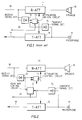
- the conventional hands-free telephone includes a speaker 16 and a microphone 17 which may be connected to a public telephone switching network (PTSN) or to a logic circuit of a mobile subscriber station through a voice receive path 18 and a voice transmit path 19.
- PTSN public telephone switching network
- a transmit variolosser (T-ATT) 15 is inserted into the transmit path 19.
- the R-ATT 11 and T-ATT 15 are under control of an attenuation control circuit 13.
- the attenuation control circuit 13 receives two signals indicating a receive voice level and a transmit voice level which are detected by detectors 12 and 14, respectively.
- the control circuit 13 also receives through a line 20 an enable or disable signal indicating whether a communications line between the hands-free telephone and PTSN is established. When the communications line is established, the control circuit 13 is enabled with the enable signal. Otherwise, the control circuit 13 is disabled with the disable signal.
- the control circuit 13 When the receive signal detector 12 detects a receive voice signal and the transmit signal detector 14 detects no transmit voice signal, the control circuit 13 causes R-ATT 11 to decrease its attenuation while causing T-ATT 15 to increase its attenuation. On the contrary, when the detector 14 detects a transmit voice signal and the detector 12 detects no receive voice signal, the control circuit 13 causes T-ATT 15 to decrease its attenuation while causing R-ATT 11 to increase its attenuation.
- voice-switched telephoning can be performed, resulting in alleviating the singing during the conversation. (Since the detailed description of the voice-switched speakerphone is given in the Busala paper, it will be omitted herein.)
- the voice-switched speakerphone still has the singing problem during the transient period from a call origination to the beginning of the conversation.
- This singing problem can be solved by the present invention which will now be described.
- Fig. 2 a first embodiment of the present invention is shown in which the same reference numerals as in Fig. 1 denote the same elements as those in Fig. 1, respectively.
- the operation of the hands-free telephone of Fig. 2 is the same as that of the telephone of Fig. 1.
- the Busala paper is therefore incorporated in this application.
- the hands-free telephone of Fig. 2 comprises an auxiliary control circuit 21 to which the outputs of the detectors 12 and 14 and the enable/disable signal on line 20 are applied.
- the auxiliary control circuit 21 Through the auxiliary control circuit 21, the output of transmit signal detector 14 is applied to the attenuation control circuit 13.
- the auxiliary control circuit 21 receives the output of receive signal detector 12 and the enable/disable signal. Based on these signals and on the output of transmit signal detector 14, the circuit 21 determines whether or not the output of transmit signal detector 14 is to be passed to the attenuation control circuit 13.
- the auxiliary control circuit 21 passes the output of detector 14 to the control circuit 13 and then holds this state until the circuit 21 receives the disable signal. In other words, the auxiliary control circuit 21 detects that a voice signal is applied to the microphone 17 to start the conversation. Thereafter, the attenuation control circuit 13 performs the voice-switched operation like the prior art telephone does. Since the transmit signal is not transmitted during the transient period, no singing occurs during this period.
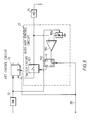
- the auxiliary control circuit 21 comprises an analog switch 101 connected between the signal detector 14 and the attenuation control circuit 13.
- the circuit 21 also comprises a comparator 103 whose non-inverting and inverting terminals are supplied with the output of signal detector 14 and the output of a reference signal generator 104, respectively.
- the reference signal generator 104 sets its output voltage to the predetermined reference level in accordance with the output level of receive signal detector 12.
- the output of comparator 103 is applied to a clock terminal CK of a flip-flop (F/F) 102.
- the data terminal D and the reset terminal R of F/F 102 are applied with a positive voltage +V and the enable/disable signal, respectively.
- the Q output of F/F 102 controls the analog switch 101.
- the analog switch 101 When the enable signal is applied to the reset terminal R of F/F 102, i.e., the communications line is established, the analog switch 101 is made open by the Q output of F/F 102. As long as the output of signal detector 14 is below the predetermined reference level, the analog switch 101 is open. If the output level of signal detector 14 exceeds the predetermined reference level, i.e., a voice signal is applied to the microphone 17 (Fig. 2) to start the conversation, the comparator 103 triggers the F/F 102 which in turn latches the positive voltage +V at the D terminal thereof to provide a high level signal at the Q terminal. This high level signal causes the analog switch 101 to be closed to thereby pass the output of signal detector 14 to the attenuation control circuit 13. Thereafter, the F/F 102 maintains this status until the disable signal is applied to the R terminal. When the analog switch 101 is closed, the voice-switched telephoning operates like the prior art speakerphone.
- the F/F 102 makes the analog switch 101 open to stop the output of signal detector 14 from reaching the attenuation control circuit 13.
- the hands-free telephone returns to the waiting state.
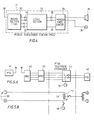
- FIG. 4 is a block diagram showing a second embodiment of the present invention which is applicable to a mobile telephone system.
- a mobile subscriber station (MSS) 31 comprises a radio transmitter/receiver (TRX) section 32, a logic section 33, a hands-free circuit 34, a speaker 35 and a microphone 36.
- Voice lines 40 and data lines 37 connect the radio section 32 and the logic section 33.
- Voice lines 38 and a data line 39 connect the logic section 33 and the hands-free circuit 34.
- the hands-free circuit 34 passes a receive signal to the speaker 35 but not a transmit signal to the logic section 33. If a call is placed by MSS 31 and the called party responds to the call, the conversation begins therebetween.
- the logic section 33 detects the beginning of the conversation by detecting a charge signal which is transmitted from a telephone exchanger and will be described later in detail. Upon detection of the beginning of the conversation, logic section 33 provides a hands-free enable signal to the hands-free circuit 34. In response to the hands-free enable signal, the circuit 34 starts the voice-switched operation and continues this operation until the conversation ends. When the conversation ends, the logic section 33 provides a hands-free disable signal to the hands-free circuit 34 to return the circuit 34 to the waiting state.
- a mobile telephone system includes a plurality of MSSs 41, a plurality of mobile base stations (MBSs) 42 and at least one mobile telephone control center (MTCC) 43. Only one of each of the MBS, MSS and MTCC are illustrated in Fig. 5A.
- MSS 41 and MBS 42 are to be connected with each other over a radio channel.
- MBS 42 and MTCC 43 are connected with each other through wired lines.
- MTCC 43 is also connected to an exchanger of PTSN through wired lines.
- PTSN includes a plurality of fixed subscriber station (FSSs) 45 which are connected to the exchanger through wired lines.
- the exchanger 44 comprises a tone oscillator 46 generating a ringback tone.
- MSS 41 If a call is originated by MSS 41 to FSS 45, MSS 41 is first connected to the exchanger through MBS 42 and MTCC 43. In this condition, the exchanger 44 sends a ringing signal to FSS 45 and a ringback tone to MSS 41. When FSS 45 goes off-hook, the exchanger 44 connects MSS 41 and FSS 45 for conversation. When either FSS 45 or MSS 41 goes on-hook, the exchanger 44 disconnects MSS 41 from FSS 45 and restores the used lines for other communications.
- the exchanger 44 Since FSS 45 is connected to the exchanger 44 through a two-wire subscriber line while MTCC 43 is connected to the same through a four-wire line, the exchanger 44 has a hybrid transformer 441 for a four-wire to two-wire conversion or vis-a-vis, as shown in Fig. 5B.
- the hybrid transformer 441 is designed so that it has minimum coupling 171 between the speaker and microphone of the MSS when MSS 41 and FSS 45 are connected with each other. In other words, during a transient period from the call origination to the beginning of the conversation, the transformer 441 is unbalanced, causing the coupling 171 to be increased. This coupling increase leads to the singing at the MSS side.
- MSS 41 also has acoustic coupling 161 between the speaker and the microphone, which coupling worsens the singing problem. This singing problem can be eliminated with the MSS of Fig. 4.
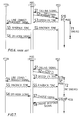
- Fig. 6 shows the operation flow of the prior art MTS for comparison with the present invention.
- MBS receives a calling signal from an MSS (see step S1)
- MBS transmits a speech or voice channel designate signal to MSS (step S2).
- MSS changes its channel to the designated speech channel and makes the receive and transmit voice gates (not shown) open to enter the hands-free (HF) operation or mode (step S10).
- HF hands-free
- the MSS transmits a channel-switch confirmation tone to the MBS/MTCC over the switched speech channel (step S3).
- the MBS/MTCC sends a line connect reguest signal to the exchanger to thereby call a called party (step S4).
- the exchanger By receiving the line connect request signal, the exchanger sends a ringing signal to the called party and at the same time sends a ringback tone to MSS through the MBS/MTCC (step S5). If the called party goes off-hook, the exchanger sends an off-hook signal to the MBS/MTCC (step S6) to start the conversation. Since the MSS is in the HF mode when the ringback tone is being sent, i.e., the hybrid transformer is unbalanced, singing may occur at the MSS side. This situation continues for a period of time T1 until the ringback tone stops, i.e., the conversation starts.
- Fig. 7 shows the operation flow of the present invention.
- steps S1 through S6 are the same operations as those of Fig. 6, except that the MSS makes only the receive voice gate open to enter a speaker (SP) operation or mode (step S13).
- the MBS/MTCC Upon reception of the off-hook signal at step S6, the MBS/MTCC transmits a telephone charge signal to the MSS (step S7).
- the MSS makes the transmit voice gate open to enter the HF mode and perform the voice-switched telephoning (step S10).
- the MSS starts a charge operation and transmits a charge response signal to the MBS/MTCC (step S8).
- the MSS When the ringback tone is being sent to the MSS, i.e., the hybrid transformer is unbalanced, the MSS is in the SP mode (see step S13). Thus, no singing will occur during this period of time T2.
- the MSS enters the HF mode only after the ringback tone stops, i.e., the hybrid transformer recovers to a well-balanced condition.
- Fig. 8 shows the operation flow of the MSS of Fig. 4.
- the MSS transmits a calling or call-up signal to the MBS/MTCC (step H1)
- the MSS waits for a channel designate signal at step H2. If the MSS receives no channel designate signal for a predetermined period of time, the MSS returns to the waiting state (steps H2, H10 and H11). If the MSS receives the channel designate signal at step H2, the MSS changes its channel to the designated speech channel (step H3). Then, the MSS sends a channel-switch confirmation signal over the switched speech channel (step H4) and enters the speaker (HP) mode (step H5).
- step H5 the MSS waits for a charge signal and if no charge signal is received for a predetermined period of time, the MSS returns to the waiting state (steps H6, H12 and H13). If the MSS receives the charge signal at step H6, the MSS proceeds to steps H7 and H8 to execute the transmission of charge response signal and the setting of hands-free (HF) mode. Thereafter, MSS starts the conversation (step H9).
- a hands-free telephone comprises an auxiliary control circuit which stops the output of a transmit voice signal detector from reaching the attenuation control circuit during a transient period between the call origination and the beginning of the conversation.
- the auxiliary control circuit stops the output of a transmit voice signal detector from reaching the attenuation control circuit during a transient period between the call origination and the beginning of the conversation.
- the singing can be prevented during the transient period.
- a hands-free mobile subscriber telephone enables only a receive voice line during the transient period during which a ringback tone is being generated from a telephone exchanger, i.e., a hybrid transformer of the exchanger is unbalanced. The mobile subscriber telephone enters the hands-free operation only after the ringback tone stops or immediately before the conversation begins.
- the singing can also be prevented during the transient period.
Description
- The present invention relates to a hands-free telephone and, more particularly, to a voice-switched type hands-free telephone which may be used for a mobile telephone system.
- A hands-free telephone has a howling or singing problem. A voice-switched speakerphone is an answer to the singing problem. Reference is made to "Fundamental Considerations in the Design of a Voice-Switched Speakerphone," by A. Busala, THE BELL SYSTEM TECHNICAL JOURNAL, Volume XXXIX, No. 2, March, 1960. To avoid the singing, the voice-switched speakerphone, which will later be described referring to Fig. 1 of the accompanying drawings, includes a receive variable attenuator, or variolosser, inserted into a receive path and a transmit variable attenuator, or variolosser, inserted into a transmit path. The voice-switched speakerphone also includes an attenuation control circuit which controls the attenuation of the receive and transmit variolossers in response to the signal levels of the receive and transmit paths.
- More specifically, when the output level of the microphone is smaller than the input level of the speaker, the attenuation control circuit causes the receive variolosser to decrease its attenuation while causing the transmit variolosser to increase its attenuation. When the output level of the microphone is larger than the input level of the speaker, the attenuation control circuit causes the receive variolosser to increase its attenuation while causing the transmit variolosser to decrease its attenuation. Thus, the voice-switched speakerphone can alleviate the singing during the conversation.
- However, the voice-switched speakerphone still has the singing problem during a transient period from the origination of a call to the beginning of the conversation. This may be caused by unbalance of a hybrid transformer of a telephone exchanger. The unbalance increases coupling between a transmit signal and a receive signal. The increasing of the coupling induces the singing at the speakerphone.
- In the mobile telephone system, a mobile base station to be connected to a mobile subscriber station is almost always changed when a call is placed from the mobile subscriber station. That is, a communications line to be connected to the mobile subscriber station is changed, resulting in changes in the coupling between the receive and transmit signals. This aggravates the singing problem during the transient period mentioned above.
- In the Specification of United States Patent No. 4,513,177, which was published on April 23 1985, there was proposed a loudspeaking telephone system with means to produce control signals related to voice signals, the control signals being used to control switching between channels under the control of loss of digitally controlled variable attenuators in the speech channel.
- Features of arrangements to be described below are a hands-free telephone which minimises the above-mentioned singing problem, and which when used in a mobile telephone system in particular is able to minimise the singing problem, especially during a transient period from the call origination to the conversation.
- In one embodiment to be described below, there is a hands-free telephone comprising a speaker, a microphone, a receive variable attenuator (R-ATT), a transmit variable attenuator (T-ATT), a receive signal detector, a transmit signal detector and an attenuation control circuit in order to perform voice-switched telephoning. The telephone also comprises an auxiliary control circuit which prevents the output of the transmit signal detector from reaching the attenuation control circuit during a transient period between a call origination and the conversation. During this period, only the speaker is enabled to output a ringback tone therethrough. When the output level of the transmit signal detector exceeds a predetermined level, the auxiliary control circuit passes the output of the transmit signal detector to the attenuation control circuit to start the voice-switched telephoning. Once the auxiliary control circuit passes the output of the transmit signal detector, the auxiliary control circuit holds this state until the conversation finishes.
- In another arrangement to be described below, there is a hands-free mobile subscriber station (MSS) used for a mobile telephone system which comprises at least one mobile base station (MBS) connected to MSS over a radio channel and to an exchanger of a public telephone switching network (PTSN). The MSS comprises a radio transmitter/receiver section, a logic section connected to the radio transmitter/receiver section, a speaker and a microphone. The MSS further comprises a hands-free circuit connected to the logic section, the speaker and the microphone. The hands-free circuit performs voice-switched telephoning during the conversation and provides a receive signal from the logic section to the speaker and no transmit signal from the microphone to the logic section during a transient period from a call origination to the beginning of the conversation.
- A previously proposed arrangement, together with embodiments of the invention given by way of example, will now be described with reference to the accompanying drawings, in which:
- Fig. 1 is a block diagram showing a prior art hands-free telephone;
- Fig. 2 is a block diagram showing an embodiment of a hands-free telephone according to the present invention;
- Fig. 3 is a block diagram showing an auxiliary control circuit in the telephone of Fig. 2;
- Fig. 4 is a block diagram showing another embodiment of a hands-free telephone according to the present invention;
- Figs. 5A and 5B show schematic block diagrams of a mobile telephone system connected to a public telephone switching network (PTSN);
- Fig. 6 is a flow chart showing the operation of the prior art mobile telephone system;
- Fig. 7 is a flow chart showing the operation of the mobile telephone system according to the present invention; and
- Fig. 8 is a flow chart showing operation of the hands-free telephone shown in Fig. 4.
- In Fig. 1, the conventional hands-free telephone includes a
speaker 16 and amicrophone 17 which may be connected to a public telephone switching network (PTSN) or to a logic circuit of a mobile subscriber station through a voice receivepath 18 and avoice transmit path 19. Into the receivepath 18 is inserted a receive variable attenuator, or variolosser, (R-ATT) 11. Similarly, a transmit variolosser (T-ATT) 15 is inserted into thetransmit path 19. The R-ATT 11 and T-ATT 15 are under control of anattenuation control circuit 13. Theattenuation control circuit 13 receives two signals indicating a receive voice level and a transmit voice level which are detected bydetectors control circuit 13 also receives through aline 20 an enable or disable signal indicating whether a communications line between the hands-free telephone and PTSN is established. When the communications line is established, thecontrol circuit 13 is enabled with the enable signal. Otherwise, thecontrol circuit 13 is disabled with the disable signal. - When the receive
signal detector 12 detects a receive voice signal and thetransmit signal detector 14 detects no transmit voice signal, thecontrol circuit 13 causes R-ATT 11 to decrease its attenuation while causing T-ATT 15 to increase its attenuation. On the contrary, when thedetector 14 detects a transmit voice signal and thedetector 12 detects no receive voice signal, thecontrol circuit 13 causes T-ATT 15 to decrease its attenuation while causing R-ATT 11 to increase its attenuation. Thus, voice-switched telephoning can be performed, resulting in alleviating the singing during the conversation. (Since the detailed description of the voice-switched speakerphone is given in the Busala paper, it will be omitted herein.) - As mentioned earlier, however, the voice-switched speakerphone still has the singing problem during the transient period from a call origination to the beginning of the conversation. This singing problem can be solved by the present invention which will now be described.
- In Fig. 2, a first embodiment of the present invention is shown in which the same reference numerals as in Fig. 1 denote the same elements as those in Fig. 1, respectively. After the conversation has started, the operation of the hands-free telephone of Fig. 2 is the same as that of the telephone of Fig. 1. The Busala paper is therefore incorporated in this application.
- The hands-free telephone of Fig. 2 comprises an
auxiliary control circuit 21 to which the outputs of thedetectors line 20 are applied. Through theauxiliary control circuit 21, the output oftransmit signal detector 14 is applied to theattenuation control circuit 13. Theauxiliary control circuit 21 receives the output of receivesignal detector 12 and the enable/disable signal. Based on these signals and on the output oftransmit signal detector 14, thecircuit 21 determines whether or not the output oftransmit signal detector 14 is to be passed to theattenuation control circuit 13. - More specifically, if the output level of
transmit signal detector 14 exceeds a predetermined reference level that is determined by the output level of receivesignal detector 12, theauxiliary control circuit 21 passes the output ofdetector 14 to thecontrol circuit 13 and then holds this state until thecircuit 21 receives the disable signal. In other words, theauxiliary control circuit 21 detects that a voice signal is applied to themicrophone 17 to start the conversation. Thereafter, theattenuation control circuit 13 performs the voice-switched operation like the prior art telephone does. Since the transmit signal is not transmitted during the transient period, no singing occurs during this period. - Referring to Fig. 3, the
auxiliary control circuit 21 comprises ananalog switch 101 connected between thesignal detector 14 and theattenuation control circuit 13. Thecircuit 21 also comprises acomparator 103 whose non-inverting and inverting terminals are supplied with the output ofsignal detector 14 and the output of areference signal generator 104, respectively. Thereference signal generator 104 sets its output voltage to the predetermined reference level in accordance with the output level of receivesignal detector 12. The output ofcomparator 103 is applied to a clock terminal CK of a flip-flop (F/F) 102. The data terminal D and the reset terminal R of F/F 102 are applied with a positive voltage +V and the enable/disable signal, respectively. The Q output of F/F 102 controls theanalog switch 101. - When the enable signal is applied to the reset terminal R of F/
F 102, i.e., the communications line is established, theanalog switch 101 is made open by the Q output of F/F 102. As long as the output ofsignal detector 14 is below the predetermined reference level, theanalog switch 101 is open. If the output level ofsignal detector 14 exceeds the predetermined reference level, i.e., a voice signal is applied to the microphone 17 (Fig. 2) to start the conversation, thecomparator 103 triggers the F/F 102 which in turn latches the positive voltage +V at the D terminal thereof to provide a high level signal at the Q terminal. This high level signal causes theanalog switch 101 to be closed to thereby pass the output ofsignal detector 14 to theattenuation control circuit 13. Thereafter, the F/F 102 maintains this status until the disable signal is applied to the R terminal. When theanalog switch 101 is closed, the voice-switched telephoning operates like the prior art speakerphone. - When the disable signal is applied to the R terminal of F/
F 102, i.e., the established communications line is released, the F/F 102 makes theanalog switch 101 open to stop the output ofsignal detector 14 from reaching theattenuation control circuit 13. Thus, the hands-free telephone returns to the waiting state. - Fig. 4 is a block diagram showing a second embodiment of the present invention which is applicable to a mobile telephone system. A mobile subscriber station (MSS) 31 comprises a radio transmitter/receiver (TRX)
section 32, alogic section 33, a hands-free circuit 34, aspeaker 35 and amicrophone 36.Voice lines 40 anddata lines 37 connect theradio section 32 and thelogic section 33.Voice lines 38 and adata line 39 connect thelogic section 33 and the hands-free circuit 34. In the waiting state and the call-up period, the hands-free circuit 34 passes a receive signal to thespeaker 35 but not a transmit signal to thelogic section 33. If a call is placed byMSS 31 and the called party responds to the call, the conversation begins therebetween. - The
logic section 33 detects the beginning of the conversation by detecting a charge signal which is transmitted from a telephone exchanger and will be described later in detail. Upon detection of the beginning of the conversation,logic section 33 provides a hands-free enable signal to the hands-free circuit 34. In response to the hands-free enable signal, thecircuit 34 starts the voice-switched operation and continues this operation until the conversation ends. When the conversation ends, thelogic section 33 provides a hands-free disable signal to the hands-free circuit 34 to return thecircuit 34 to the waiting state. - In Fig. 5A, a mobile telephone system (MTS) includes a plurality of
MSSs 41, a plurality of mobile base stations (MBSs) 42 and at least one mobile telephone control center (MTCC) 43. Only one of each of the MBS, MSS and MTCC are illustrated in Fig. 5A.MSS 41 andMBS 42 are to be connected with each other over a radio channel.MBS 42 andMTCC 43 are connected with each other through wired lines.MTCC 43 is also connected to an exchanger of PTSN through wired lines. PTSN includes a plurality of fixed subscriber station (FSSs) 45 which are connected to the exchanger through wired lines. Theexchanger 44 comprises atone oscillator 46 generating a ringback tone. - If a call is originated by
MSS 41 toFSS 45,MSS 41 is first connected to the exchanger throughMBS 42 andMTCC 43. In this condition, theexchanger 44 sends a ringing signal toFSS 45 and a ringback tone toMSS 41. WhenFSS 45 goes off-hook, theexchanger 44 connectsMSS 41 andFSS 45 for conversation. When eitherFSS 45 orMSS 41 goes on-hook, theexchanger 44 disconnects MSS 41 fromFSS 45 and restores the used lines for other communications. - Since
FSS 45 is connected to theexchanger 44 through a two-wire subscriber line whileMTCC 43 is connected to the same through a four-wire line, theexchanger 44 has ahybrid transformer 441 for a four-wire to two-wire conversion or vis-a-vis, as shown in Fig. 5B. Thehybrid transformer 441 is designed so that it hasminimum coupling 171 between the speaker and microphone of the MSS whenMSS 41 andFSS 45 are connected with each other. In other words, during a transient period from the call origination to the beginning of the conversation, thetransformer 441 is unbalanced, causing thecoupling 171 to be increased. This coupling increase leads to the singing at the MSS side.MSS 41 also has acoustic coupling 161 between the speaker and the microphone, which coupling worsens the singing problem. This singing problem can be eliminated with the MSS of Fig. 4. - More detailed description of the Fig. 4 MSS and of the Figs. 5A and 5B MTS will now be provided with reference to Figs. 6-8. Fig. 6 shows the operation flow of the prior art MTS for comparison with the present invention. In Fig. 6, when MBS receives a calling signal from an MSS (see step S1), MBS (or MTCC) transmits a speech or voice channel designate signal to MSS (step S2). Upon reception of the speech channel designate signal, MSS changes its channel to the designated speech channel and makes the receive and transmit voice gates (not shown) open to enter the hands-free (HF) operation or mode (step S10). Thereafter, the MSS transmits a channel-switch confirmation tone to the MBS/MTCC over the switched speech channel (step S3). In response to the tone, the MBS/MTCC sends a line connect reguest signal to the exchanger to thereby call a called party (step S4).
- By receiving the line connect request signal, the exchanger sends a ringing signal to the called party and at the same time sends a ringback tone to MSS through the MBS/MTCC (step S5). If the called party goes off-hook, the exchanger sends an off-hook signal to the MBS/MTCC (step S6) to start the conversation. Since the MSS is in the HF mode when the ringback tone is being sent, i.e., the hybrid transformer is unbalanced, singing may occur at the MSS side. This situation continues for a period of time T1 until the ringback tone stops, i.e., the conversation starts.
- Fig. 7 shows the operation flow of the present invention. In Fig. 7, steps S1 through S6 are the same operations as those of Fig. 6, except that the MSS makes only the receive voice gate open to enter a speaker (SP) operation or mode (step S13). Upon reception of the off-hook signal at step S6, the MBS/MTCC transmits a telephone charge signal to the MSS (step S7). In response to the charge signal, the MSS makes the transmit voice gate open to enter the HF mode and perform the voice-switched telephoning (step S10). At the same time, the MSS starts a charge operation and transmits a charge response signal to the MBS/MTCC (step S8).
- When the ringback tone is being sent to the MSS, i.e., the hybrid transformer is unbalanced, the MSS is in the SP mode (see step S13). Thus, no singing will occur during this period of time T2. The MSS enters the HF mode only after the ringback tone stops, i.e., the hybrid transformer recovers to a well-balanced condition.
- Fig. 8 shows the operation flow of the MSS of Fig. 4. After the MSS transmits a calling or call-up signal to the MBS/MTCC (step H1), the MSS waits for a channel designate signal at step H2. If the MSS receives no channel designate signal for a predetermined period of time, the MSS returns to the waiting state (steps H2, H10 and H11). If the MSS receives the channel designate signal at step H2, the MSS changes its channel to the designated speech channel (step H3). Then, the MSS sends a channel-switch confirmation signal over the switched speech channel (step H4) and enters the speaker (HP) mode (step H5).
- After step H5, the MSS waits for a charge signal and if no charge signal is received for a predetermined period of time, the MSS returns to the waiting state (steps H6, H12 and H13). If the MSS receives the charge signal at step H6, the MSS proceeds to steps H7 and H8 to execute the transmission of charge response signal and the setting of hands-free (HF) mode. Thereafter, MSS starts the conversation (step H9).
- As described hereinbefore, according to one aspect of the present invention, a hands-free telephone comprises an auxiliary control circuit which stops the output of a transmit voice signal detector from reaching the attenuation control circuit during a transient period between the call origination and the beginning of the conversation. Thus, by employing the auxiliary control circuit, the singing can be prevented during the transient period. In addition, according to another aspect of the present invention, a hands-free mobile subscriber telephone enables only a receive voice line during the transient period during which a ringback tone is being generated from a telephone exchanger, i.e., a hybrid transformer of the exchanger is unbalanced. The mobile subscriber telephone enters the hands-free operation only after the ringback tone stops or immediately before the conversation begins. Thus, the singing can also be prevented during the transient period.
Claims (15)
- A hands-free telephone including a speaker (16), a microphone (17), a receive variable attenuator (11) connected to the input of the speaker (16) for changing the input level of the speaker (16) in accordance with a first control signal, a transmit variable attenuator (15) connected to the output of the microphone (17) for changing the output level of the microphone (17) in accordance with a second control signal, a receive signal detector (12) connected to the input of the receive variable attenuator (11) for detecting the input level of the receive variable attenuator (11) to produce a receive detect signal, a transmit signal detector (14) connected to the output of the microphone (17) for detecting the output level of the microphone (17) to produce a transmit detect signal, and an attenuation control (13) responsive to the receive and transmit detect signals for providing the first and second control signals to the receive and transmit variable attenuators (11, 15) respectively, characterised in that an auxiliary control (21) is connected between the transmit signal detector (14) and the attenuation control (13), and in that the auxiliary control (21) is responsive to an enable/disable signal indicating the status of a line connected to the hands-free telephone for passing the transmit detect signal to the attenuation control (13) only when the transmit detect signal exceeds a predetermined reference level and the enable/disable signal indicates that the line is established.
- A hands-free telephone as claimed in claim 1, wherein the auxiliary control (21) includes a reference level generator (104) responsive to the receive detect signal for generating a signal having the predetermined reference level.
- A hands-free telephone as claimed in claim 1, wherein the auxiliary control (21) includes a comparator (103) for comparing the level of the transmit detect signal with the predetermined reference level and for providing a comparison signal when the level of the transmit detect signal exceeds the predetermined reference signal, a flip-flop (102) having Q and
Q terminals and also having data, clock and reset terminals which receive a positive voltage, the comparison signal and the enable/disable signal, respectively, and an analog switch (101) for selectively passing the transmit detect signal to the attenuation control (13) based on a signal at one of the Q andQ terminals. - A hands-free telephone including a speaker (16) for receiving a receive signal, a microphone (17) for transmitting a transmit signal, a receive attenuator (11) for changing the level of the receive signal in accordance with a first control signal, a transmit attenuator (15) for changing the level of the transmit signal in accordance with a second control signal, a receive signal detector (12) for detecting the level of the receive signal to produce a receive detect signal, and a transmit signal detector (14) for detecting the level of the transmit signal to produce a transmit detect signal, characterised in that there are further provided a first control (21) for passing the transmit detect signal when the level of the transmit detect signal exceeds a reference level and for holding the passing status until the first control (21) receives a reset signal, and a second control (13) responsive to the receive detect signal and to the output of the first control (21) for providing the first and second control signals to the receive and the transmit attenuator (11, 15), respectively.
- A hands-free telephone as claimed in claim 4, wherein the first control (21) includes means (104) responsive to the receive detect signal for generating a signal having the reference level.
- A hands-free telephone as claimed in claim 4, wherein the first control (21) includes an analog switch (101) for passing the transmit detect signal to the second control (13) in response to a third control signal, a comparator (103) for producing a comparison signal when the level of the transmit detect signal exceeds the reference level, and holding means (102) responsive to the comparison signal for providing the third control signal to the analog switch (101) and holding the provision of the third control signal to the analog switch (101) until the holding means (102) is reset.
- A hands-free telephone as claimed in claim 6, wherein the holding means (102) includes a flip-flop (102) having data and clock terminals which receive a positive voltage and the comparison signal, respectively, and an output terminal at which the third control signal is provided.
- A hands-free mobile subscriber station (MSS) (31, 41) for use in a mobile telephone system which includes at least one mobile base station (MBS) (42) connected to the MSS (31, 41) over a radio channel and to an exchanger (44) of a public telephone switching network, the MSS (31, 41) including a radio transmitter and a radio receiver (32), a logic section (33) connected to the radio transmitter and receiver (32), a speaker (35), a microphone (36), and a hands-free circuit (34) connected to the logic section (33), the speaker (35) and the microphone (36) for enabling voice-switching to occur during conversations between the MSS (31, 41) and another party (45), characterised in that the hands-free circuit (34) enables a receive signal to pass from the logic section (33) to the speaker (35) and inhibits a transmit signal passing from the microphone (36) to the logic section (33) during a transient period between a call origination and the beginning of a conversation.
- A hands-free MSS as claimed in claim 8, characterised in that the MBS (42) includes means for sending a speech channel designate signal to the MSS (31, 41) in response to a call origination from the MSS (31, 41), in that the MSS (31, 41) changes, in response to the speech channel designate signal, its channel to a speech channel which is designated by the speech channel designate signal and sends a channel-switch confirmation tone to the MBS (42), in that the hands-free circuit (34) provides, in response to the speech channel designate signal, a receive signal from the logic section means (33) to the speaker means (35), in that the MBS (42) includes means for sending, in response to the channel-switch confirmation signal, a line connect request signal to the exchanger (44), in that the exchanger (44) includes means for sending, in response to the line connect request signal, a ringback tone to the MSS (31, 41) for sending, in response to an off-hook condition by another party (45), an off-hook signal to the MBS (42), in that the MBS (42) includes means for sending, in response to the off-hook signal, a charge signal to the MSS (31, 41), and in that the MSS (31, 41) includes means for sending, in response to the charge signal, a charge response signal to the MBS (42) to start a voice-switched telephone operation.
- Hands-free control means for use in a voice-switching type telephone, including a receive attenuator (11), a receive signal detector (12), a transmit attenuator (15), and a transmit signal detector (14) characterised in that there are further provided an auxiliary control (21) including a comparison voltage generator (104) responsive to the output of the receive signal detector (12) for generating a comparison reference voltage, a comparator (103) for comparing the outputs of the comparison voltage generator (104) and the transmit signal detector (14), a flip-flop (102) having a clock terminal and receiving the output of the comparator (103) at the clock terminal, and an analog switch (101) responsive to an output of the flip-flop (102), and in that, when the output of the transmit signal detector (14) exceeds the comparison reference voltage, the output of the flip-flop (102) signals the analog switch (101) in its closed state to supply the output of the transmit signal detector (14) to the hands-free control means.
- A method of controlling a hands-free telephone adapted for use in a mobile telephone system in which when a mobile subscriber station MSS (41) places a call, a mobile base station MBS (42) connects together the MSS (31, 41) and a called party (45) and when the called party (45) responds to the call, the MBS (42) transmits a conversation start signal to the MSS (31, 41), the method including the step of transmitting a speech channel designate signal from the MBS (42) to the MSS (31, 41), characterised in that responsive to the speech channel designate signal, the method further includes the steps of enabling a speaker (35) of the MSS (31, 41) to output a ringback tone therethrough while disabling a microphone (36) of the MSS (31, 41), and in that, responsive to the conversation start signal, the microphone (36) is enabled to start the hands-free telephoning.
- A method of controlling a voice-switched type hands-free telephone which includes a speaker (16) and a microphone (17), the method including the steps of changing the level of a receive signal in accordance with a first control signal, the receive signal being applied to the speaker (16), changing the level of a transmit signal in accordance with a second control signal, the transmit signal being provided from the microphone (17), detecting the level of the receive signal to provide a receive detect signal, detecting the level of the transmit signal to provide a transmit detect signal, and providing the receive signal to the speaker (16) when a line is established between the telephone and a party to whom a call is placed from the telephone, characterised in that the method further includes the steps of passing the transmit detect signal when the level of the transmit detect signal exceeds a predetermined level and continuing the passing of the transmit detect signal until the established line is released, and, responsive to the receive detect signal and to the passed transmit detect signal, producing the first and second control signals so that the telephone performs a voice-switched operation.
- A method as claimed in claim 12, further including the step of generating a signal having the predetermined level in response to the receive detect signal.
- A method as claimed in claim 12, wherein the step of passing the transmit detect signal includes the steps of passing the transmit detect signal responsive to a third control signal, producing a comparison signal when the level of the transmit detect signal exceeds the predetermined level, producing the third control signal responsive to the comparison signal, and holding the production of the third control signal until the established line is released.
- A method of controlling a hands-free mobile telephone which includes a speaker (35) and a microphone (36), the method including the steps of transmitting (H1) a calling signal, checking (H2) if a channel designate signal is received, returning (H10, H11) the telephone to a waiting state if the channel designate signal is not received, switching (H3) the channel of the telephone to a channel which is designated by the channel designate signal, if the channel designate signal is received, and transmitting (H4) a tone over the switched channel, characterised in that the method further includes the steps of enabling (H5) the speaker (35) in response to the transmission of the tone, checking (H6) if a charge signal is received, returning (H12, H13) the telephone to the waiting state if the charge signal is not received, transmitting (H7) a charge response signal and enabling the microphone (36) if the charge signal is received, and performing (H8) a voice-switched telephone operation with respect to the speaker (35) and microphone (36) responsive to the enabling of the microphone (36).
Applications Claiming Priority (4)
| Application Number | Priority Date | Filing Date | Title |
|---|---|---|---|
| JP33902/88 | 1988-02-18 | ||
| JP3390288 | 1988-02-18 | ||
| JP252046/88 | 1988-10-07 | ||
| JP63252046A JP2751244B2 (en) | 1988-02-18 | 1988-10-07 | Hands-free circuit and hands-free control method |
Publications (3)
| Publication Number | Publication Date |
|---|---|
| EP0330384A2 EP0330384A2 (en) | 1989-08-30 |
| EP0330384A3 EP0330384A3 (en) | 1990-06-13 |
| EP0330384B1 true EP0330384B1 (en) | 1993-11-03 |
Family
ID=26372678
Family Applications (1)
| Application Number | Title | Priority Date | Filing Date |
|---|---|---|---|
| EP89301554A Expired - Lifetime EP0330384B1 (en) | 1988-02-18 | 1989-02-17 | Hands-free telephone |
Country Status (6)
| Country | Link |
|---|---|
| US (2) | US4982425A (en) |
| EP (1) | EP0330384B1 (en) |
| JP (1) | JP2751244B2 (en) |
| CA (1) | CA1308441C (en) |
| DE (1) | DE68910346D1 (en) |
| HK (1) | HK84597A (en) |
Families Citing this family (22)
| Publication number | Priority date | Publication date | Assignee | Title |
|---|---|---|---|---|
| US5212722A (en) * | 1989-07-24 | 1993-05-18 | Nec Corporation | Hands-free telephone having a handset volume attenuator for controlling speaker volume in a hands-free adaptor |
| US5172408A (en) * | 1990-08-01 | 1992-12-15 | At&T Bell Laboratories | Speakerphone state-controlled alerting arrangement |
| JP2634946B2 (en) * | 1990-11-19 | 1997-07-30 | 日本電気株式会社 | Hands-free auxiliary circuit |
| JPH04323938A (en) * | 1991-04-23 | 1992-11-13 | Toshiba Corp | Hand-free circuit |
| JPH04363918A (en) * | 1991-06-11 | 1992-12-16 | Toshiba Corp | Telephone system |
| US5271057A (en) * | 1991-10-09 | 1993-12-14 | Bell Communications Research, Inc. | Audio processing system for teleconferencing system |
| JP2894881B2 (en) * | 1991-10-28 | 1999-05-24 | 日本電気株式会社 | Wireless loudspeaker |
| JP4203122B2 (en) * | 1991-12-31 | 2008-12-24 | ユニシス・パルスポイント・コミュニケーションズ | Voice control communication apparatus and processing method |
| US5230089A (en) * | 1992-02-03 | 1993-07-20 | Motorola | Automated voice operated transmitter control |
| WO1993017750A1 (en) * | 1992-02-28 | 1993-09-16 | Scimed Life Systems, Inc. | Intravascular catheter and method for use thereof |
| US5297183A (en) * | 1992-04-13 | 1994-03-22 | Vcs Industries, Inc. | Speech recognition system for electronic switches in a cellular telephone or personal communication network |
| US5365583A (en) * | 1992-07-02 | 1994-11-15 | Polycom, Inc. | Method for fail-safe operation in a speaker phone system |
| JPH06216986A (en) * | 1993-01-19 | 1994-08-05 | Mitsubishi Electric Corp | Hand-free speech circuit |
| JPH06338934A (en) * | 1993-05-25 | 1994-12-06 | Exar Corp | Speaker horn with phenomenon driving type control circuit |
| US5434912A (en) * | 1993-08-11 | 1995-07-18 | Bell Communications Research, Inc. | Audio processing system for point-to-point and multipoint teleconferencing |
| GB2281680B (en) * | 1993-08-27 | 1998-08-26 | Motorola Inc | A voice activity detector for an echo suppressor and an echo suppressor |
| US5838787A (en) * | 1996-06-27 | 1998-11-17 | Northern Telecom Limited | Method and system for controlling echo return loss using a complementary variolosses in transmit path |
| US5963877A (en) * | 1997-01-30 | 1999-10-05 | Sony Corporation | Telephone call receiver indicator |
| JP3220979B2 (en) * | 1998-01-09 | 2001-10-22 | 日本電気株式会社 | Voice switch |
| DE10120525A1 (en) | 2001-04-26 | 2002-11-07 | Harman Audio Electronic Sys | Circuit arrangement for audio reproduction and hands-free talking in a motor vehicle |
| US20060136201A1 (en) * | 2004-12-22 | 2006-06-22 | Motorola, Inc. | Hands-free push-to-talk radio |
| US7792136B2 (en) * | 2007-01-31 | 2010-09-07 | Harris Corporation | Carrier sense multiple access (CSMA) for non-packetized wireless digital voice networks using intelligent conversation boundary detection |
Family Cites Families (18)
| Publication number | Priority date | Publication date | Assignee | Title |
|---|---|---|---|---|
| GB1029163A (en) * | 1964-05-29 | 1966-05-11 | Standard Telephones Cables Ltd | Improvements in or relating to telephone sets |
| US3894187A (en) * | 1973-10-31 | 1975-07-08 | Tokyo Shibaura Electric Co | Circuit for comparing at least two input signals to generate control signals |
| US3970786A (en) * | 1974-06-27 | 1976-07-20 | Stromberg-Carlson Corporation | Loudspeaking telephone with improved receive sensitivity |
| JPS5229566A (en) * | 1975-08-31 | 1977-03-05 | Showa Electric Wire & Cable Co Ltd | Manufacturing process of elastic clasp |
| US4308427A (en) * | 1979-09-06 | 1981-12-29 | Southwest Utilities, Inc. | Hands-free talk-back intercommunication system |
| JPS5787656A (en) * | 1980-11-21 | 1982-06-01 | Nippon Telegr & Teleph Corp <Ntt> | Loudspeaker transmitting system |
| JPS5797262A (en) * | 1980-12-09 | 1982-06-16 | Nippon Telegr & Teleph Corp <Ntt> | Loud speaker telephone set system |
| JPS5880937A (en) * | 1981-11-06 | 1983-05-16 | Matsushita Electric Ind Co Ltd | Voice switch call device |
| US4400584A (en) * | 1982-04-05 | 1983-08-23 | Motorola, Inc. | Speakerphone for radio and, landline telephones |
| GB2122851B (en) * | 1982-06-10 | 1986-03-19 | Standard Telephones Cables Ltd | Loudspeaking telephones |
| JPS596655A (en) * | 1982-07-02 | 1984-01-13 | Toa Tokushu Denki Kk | Telephone set |
| JPS5962259A (en) * | 1982-10-01 | 1984-04-09 | Matsushita Electric Ind Co Ltd | Sound switching device |
| FR2571191B1 (en) * | 1984-10-02 | 1986-12-26 | Renault | RADIOTELEPHONE SYSTEM, PARTICULARLY FOR MOTOR VEHICLE |
| JPH063950B2 (en) * | 1985-02-28 | 1994-01-12 | 株式会社東芝 | Loud phone |
| JPS61205029A (en) * | 1985-03-08 | 1986-09-11 | Nec Corp | Radio telephone equipment |
| DE3570569D1 (en) * | 1985-09-03 | 1989-06-29 | Motorola Inc | Hands-free control system for a radiotelephone |
| US4724540A (en) * | 1986-09-02 | 1988-02-09 | Motorola, Inc. | Speakerphone with fast idle mode |
| GB2197166A (en) * | 1986-11-07 | 1988-05-11 | Storno As | Controlling gain in speech-controlled telephones |
-
1988
- 1988-10-07 JP JP63252046A patent/JP2751244B2/en not_active Expired - Fee Related
-
1989
- 1989-02-17 CA CA000591453A patent/CA1308441C/en not_active Expired - Fee Related
- 1989-02-17 EP EP89301554A patent/EP0330384B1/en not_active Expired - Lifetime
- 1989-02-17 DE DE89301554T patent/DE68910346D1/en not_active Expired - Lifetime
- 1989-02-21 US US07/313,209 patent/US4982425A/en not_active Expired - Lifetime
- 1989-10-05 US US07/417,617 patent/US5054061A/en not_active Expired - Lifetime
-
1997
- 1997-06-19 HK HK84597A patent/HK84597A/en not_active IP Right Cessation
Also Published As
| Publication number | Publication date |
|---|---|
| JPH01295554A (en) | 1989-11-29 |
| JP2751244B2 (en) | 1998-05-18 |
| DE68910346D1 (en) | 1993-12-09 |
| EP0330384A2 (en) | 1989-08-30 |
| CA1308441C (en) | 1992-10-06 |
| US4982425A (en) | 1991-01-01 |
| HK84597A (en) | 1997-06-27 |
| US5054061A (en) | 1991-10-01 |
| EP0330384A3 (en) | 1990-06-13 |
Similar Documents
| Publication | Publication Date | Title |
|---|---|---|
| EP0330384B1 (en) | Hands-free telephone | |
| JPH01274523A (en) | Cellular data telephone system and its communication method | |
| US5259020A (en) | Portable-to-portable call transfer system for cordless telephone | |
| US4574164A (en) | Ringing signal transmission system for radiotelephone system | |
| JPH11196178A (en) | Automatic level adjusting device | |
| US5414763A (en) | Apparatus and method for providing echo suppression to a plurality of telephones | |
| JP2806702B2 (en) | Digital cordless button telephone device | |
| JP2515897B2 (en) | Cordless telephone equipment | |
| JP3308067B2 (en) | Cordless telephone | |
| JP3141462B2 (en) | Wireless telephone equipment | |
| JPS63248271A (en) | Communication equipment | |
| JPS59229964A (en) | Voice switch circuit | |
| JP2002084369A (en) | Telephone adapter | |
| KR19980074199A (en) | Mobile phone and control method with portable handsfree function using wired remote control | |
| JPH04286259A (en) | Isdn telephone set | |
| JPH06112890A (en) | Extension connection method for cordless telephone set | |
| JPH0359633B2 (en) | ||
| JPH04132357A (en) | Automatic answering telephone system | |
| JPH01208948A (en) | Telephone set | |
| JPH03162143A (en) | Subscriber's terminal control circuit | |
| JPH05160920A (en) | Communication control unit | |
| JPH04196664A (en) | Network additional device | |
| JPH05316250A (en) | Facsimile equipment | |
| JPH0998484A (en) | Cordless telephone system | |
| KR19980084186A (en) | How to Automatically Receive Calls While on the Phone |
Legal Events
| Date | Code | Title | Description |
|---|---|---|---|
| PUAI | Public reference made under article 153(3) epc to a published international application that has entered the european phase |
Free format text: ORIGINAL CODE: 0009012 |
|
| 17P | Request for examination filed |
Effective date: 19890314 |
|
| AK | Designated contracting states |
Kind code of ref document: A2 Designated state(s): DE GB NL |
|
| PUAL | Search report despatched |
Free format text: ORIGINAL CODE: 0009013 |
|
| RHK1 | Main classification (correction) |
Ipc: H04M 9/10 |
|
| AK | Designated contracting states |
Kind code of ref document: A3 Designated state(s): DE GB NL |
|
| 17Q | First examination report despatched |
Effective date: 19920702 |
|
| GRAA | (expected) grant |
Free format text: ORIGINAL CODE: 0009210 |
|
| AK | Designated contracting states |
Kind code of ref document: B1 Designated state(s): DE GB NL |
|
| PG25 | Lapsed in a contracting state [announced via postgrant information from national office to epo] |
Ref country code: NL Effective date: 19931103 Ref country code: DE Effective date: 19931103 |
|
| REF | Corresponds to: |
Ref document number: 68910346 Country of ref document: DE Date of ref document: 19931209 |
|
| NLV1 | Nl: lapsed or annulled due to failure to fulfill the requirements of art. 29p and 29m of the patents act | ||
| PLBE | No opposition filed within time limit |
Free format text: ORIGINAL CODE: 0009261 |
|
| STAA | Information on the status of an ep patent application or granted ep patent |
Free format text: STATUS: NO OPPOSITION FILED WITHIN TIME LIMIT |
|
| 26N | No opposition filed | ||
| REG | Reference to a national code |
Ref country code: GB Ref legal event code: IF02 |
|
| PGFP | Annual fee paid to national office [announced via postgrant information from national office to epo] |
Ref country code: GB Payment date: 20060215 Year of fee payment: 18 |
|
| GBPC | Gb: european patent ceased through non-payment of renewal fee |
Effective date: 20070217 |
|
| PG25 | Lapsed in a contracting state [announced via postgrant information from national office to epo] |
Ref country code: GB Free format text: LAPSE BECAUSE OF NON-PAYMENT OF DUE FEES Effective date: 20070217 |