EP0329454A2 - Pneumatic tires - Google Patents
Pneumatic tires Download PDFInfo
- Publication number
- EP0329454A2 EP0329454A2 EP89301532A EP89301532A EP0329454A2 EP 0329454 A2 EP0329454 A2 EP 0329454A2 EP 89301532 A EP89301532 A EP 89301532A EP 89301532 A EP89301532 A EP 89301532A EP 0329454 A2 EP0329454 A2 EP 0329454A2
- Authority
- EP
- European Patent Office
- Prior art keywords
- sealing material
- pneumatic tire
- tire
- continuous layer
- rubber composition
- Prior art date
- Legal status (The legal status is an assumption and is not a legal conclusion. Google has not performed a legal analysis and makes no representation as to the accuracy of the status listed.)
- Granted
Links
Images


Classifications
-
- B—PERFORMING OPERATIONS; TRANSPORTING
- B29—WORKING OF PLASTICS; WORKING OF SUBSTANCES IN A PLASTIC STATE IN GENERAL
- B29D—PRODUCING PARTICULAR ARTICLES FROM PLASTICS OR FROM SUBSTANCES IN A PLASTIC STATE
- B29D30/00—Producing pneumatic or solid tyres or parts thereof
- B29D30/06—Pneumatic tyres or parts thereof (e.g. produced by casting, moulding, compression moulding, injection moulding, centrifugal casting)
- B29D30/0681—Parts of pneumatic tyres; accessories, auxiliary operations
- B29D30/0685—Incorporating auto-repairing or self-sealing arrangements or agents on or into tyres
-
- B—PERFORMING OPERATIONS; TRANSPORTING
- B29—WORKING OF PLASTICS; WORKING OF SUBSTANCES IN A PLASTIC STATE IN GENERAL
- B29C—SHAPING OR JOINING OF PLASTICS; SHAPING OF MATERIAL IN A PLASTIC STATE, NOT OTHERWISE PROVIDED FOR; AFTER-TREATMENT OF THE SHAPED PRODUCTS, e.g. REPAIRING
- B29C73/00—Repairing of articles made from plastics or substances in a plastic state, e.g. of articles shaped or produced by using techniques covered by this subclass or subclass B29D
- B29C73/16—Auto-repairing or self-sealing arrangements or agents
- B29C73/163—Sealing compositions or agents, e.g. combined with propellant agents
-
- B—PERFORMING OPERATIONS; TRANSPORTING
- B29—WORKING OF PLASTICS; WORKING OF SUBSTANCES IN A PLASTIC STATE IN GENERAL
- B29C—SHAPING OR JOINING OF PLASTICS; SHAPING OF MATERIAL IN A PLASTIC STATE, NOT OTHERWISE PROVIDED FOR; AFTER-TREATMENT OF THE SHAPED PRODUCTS, e.g. REPAIRING
- B29C73/00—Repairing of articles made from plastics or substances in a plastic state, e.g. of articles shaped or produced by using techniques covered by this subclass or subclass B29D
- B29C73/16—Auto-repairing or self-sealing arrangements or agents
- B29C73/18—Auto-repairing or self-sealing arrangements or agents the article material itself being self-sealing, e.g. by compression
- B29C73/20—Auto-repairing or self-sealing arrangements or agents the article material itself being self-sealing, e.g. by compression the article material only consisting in part of a deformable sealing material
-
- B—PERFORMING OPERATIONS; TRANSPORTING
- B29—WORKING OF PLASTICS; WORKING OF SUBSTANCES IN A PLASTIC STATE IN GENERAL
- B29C—SHAPING OR JOINING OF PLASTICS; SHAPING OF MATERIAL IN A PLASTIC STATE, NOT OTHERWISE PROVIDED FOR; AFTER-TREATMENT OF THE SHAPED PRODUCTS, e.g. REPAIRING
- B29C73/00—Repairing of articles made from plastics or substances in a plastic state, e.g. of articles shaped or produced by using techniques covered by this subclass or subclass B29D
- B29C73/16—Auto-repairing or self-sealing arrangements or agents
- B29C73/22—Auto-repairing or self-sealing arrangements or agents the article containing elements including a sealing composition, e.g. powder being liberated when the article is damaged
-
- B—PERFORMING OPERATIONS; TRANSPORTING
- B29—WORKING OF PLASTICS; WORKING OF SUBSTANCES IN A PLASTIC STATE IN GENERAL
- B29D—PRODUCING PARTICULAR ARTICLES FROM PLASTICS OR FROM SUBSTANCES IN A PLASTIC STATE
- B29D30/00—Producing pneumatic or solid tyres or parts thereof
- B29D30/06—Pneumatic tyres or parts thereof (e.g. produced by casting, moulding, compression moulding, injection moulding, centrifugal casting)
- B29D30/0681—Parts of pneumatic tyres; accessories, auxiliary operations
- B29D30/0685—Incorporating auto-repairing or self-sealing arrangements or agents on or into tyres
- B29D2030/0686—Incorporating sealants on or into tyres not otherwise provided for; auxiliary operations therefore, e.g. preparation of the tyre
- B29D2030/0695—Incorporating sealants on or into tyres not otherwise provided for; auxiliary operations therefore, e.g. preparation of the tyre the sealant being in the form of one wide strip, e.g. a patch
-
- B—PERFORMING OPERATIONS; TRANSPORTING
- B29—WORKING OF PLASTICS; WORKING OF SUBSTANCES IN A PLASTIC STATE IN GENERAL
- B29L—INDEXING SCHEME ASSOCIATED WITH SUBCLASS B29C, RELATING TO PARTICULAR ARTICLES
- B29L2030/00—Pneumatic or solid tyres or parts thereof
-
- Y—GENERAL TAGGING OF NEW TECHNOLOGICAL DEVELOPMENTS; GENERAL TAGGING OF CROSS-SECTIONAL TECHNOLOGIES SPANNING OVER SEVERAL SECTIONS OF THE IPC; TECHNICAL SUBJECTS COVERED BY FORMER USPC CROSS-REFERENCE ART COLLECTIONS [XRACs] AND DIGESTS
- Y10—TECHNICAL SUBJECTS COVERED BY FORMER USPC
- Y10T—TECHNICAL SUBJECTS COVERED BY FORMER US CLASSIFICATION
- Y10T152/00—Resilient tires and wheels
- Y10T152/10—Tires, resilient
- Y10T152/10495—Pneumatic tire or inner tube
- Y10T152/10666—Automatic sealing of punctures [e.g., self-healing, etc.]
- Y10T152/10675—Using flowable coating or composition
- Y10T152/10684—On inner surface of tubeless tire
-
- Y—GENERAL TAGGING OF NEW TECHNOLOGICAL DEVELOPMENTS; GENERAL TAGGING OF CROSS-SECTIONAL TECHNOLOGIES SPANNING OVER SEVERAL SECTIONS OF THE IPC; TECHNICAL SUBJECTS COVERED BY FORMER USPC CROSS-REFERENCE ART COLLECTIONS [XRACs] AND DIGESTS
- Y10—TECHNICAL SUBJECTS COVERED BY FORMER USPC
- Y10T—TECHNICAL SUBJECTS COVERED BY FORMER US CLASSIFICATION
- Y10T152/00—Resilient tires and wheels
- Y10T152/10—Tires, resilient
- Y10T152/10495—Pneumatic tire or inner tube
- Y10T152/10666—Automatic sealing of punctures [e.g., self-healing, etc.]
- Y10T152/10675—Using flowable coating or composition
- Y10T152/10684—On inner surface of tubeless tire
- Y10T152/10693—Sealant in plural layers or plural pockets
-
- Y—GENERAL TAGGING OF NEW TECHNOLOGICAL DEVELOPMENTS; GENERAL TAGGING OF CROSS-SECTIONAL TECHNOLOGIES SPANNING OVER SEVERAL SECTIONS OF THE IPC; TECHNICAL SUBJECTS COVERED BY FORMER USPC CROSS-REFERENCE ART COLLECTIONS [XRACs] AND DIGESTS
- Y10—TECHNICAL SUBJECTS COVERED BY FORMER USPC
- Y10T—TECHNICAL SUBJECTS COVERED BY FORMER US CLASSIFICATION
- Y10T428/00—Stock material or miscellaneous articles
- Y10T428/24—Structurally defined web or sheet [e.g., overall dimension, etc.]
- Y10T428/24149—Honeycomb-like
- Y10T428/24157—Filled honeycomb cells [e.g., solid substance in cavities, etc.]
-
- Y—GENERAL TAGGING OF NEW TECHNOLOGICAL DEVELOPMENTS; GENERAL TAGGING OF CROSS-SECTIONAL TECHNOLOGIES SPANNING OVER SEVERAL SECTIONS OF THE IPC; TECHNICAL SUBJECTS COVERED BY FORMER USPC CROSS-REFERENCE ART COLLECTIONS [XRACs] AND DIGESTS
- Y10—TECHNICAL SUBJECTS COVERED BY FORMER USPC
- Y10T—TECHNICAL SUBJECTS COVERED BY FORMER US CLASSIFICATION
- Y10T428/00—Stock material or miscellaneous articles
- Y10T428/24—Structurally defined web or sheet [e.g., overall dimension, etc.]
- Y10T428/24273—Structurally defined web or sheet [e.g., overall dimension, etc.] including aperture
- Y10T428/24322—Composite web or sheet
- Y10T428/24331—Composite web or sheet including nonapertured component
- Y10T428/24339—Keyed
- Y10T428/24347—From both sides
Definitions
- the present invention relates to pneumatic tires which can remarkably decrease the rate at which air leaks when a tire is punctured by a nail or the like.
- the present invention aims to overcome or at least mitigate the above-mentioned problems, and to provide pneumatic tires in which air leakage is reduced while other tire performances are not significantly adversely affected.
- the present invention provides a pneumatic tire comprising a carcass ply, two vulcanized rubber composition layers arranged radially inside the carcass ply, a continuous layer of a sealing material arranged between the two vulcanized rubber composition layers, the sealing material having a viscosity of not more than 6 ⁇ 104 poises at 60°C, and bonding portions discontinuously bonding the two vulcanized rubber composition layers, the bonding portions passing through the continuous layer.
- the sealing material used for the sealing material layer in the present invention is mainly composed of at least one material selected from polyethylene, polypropylene, polybutadiene, polyisoprene, polyisoprene-butadiene copolymer, polystyrene-butadiene copolymer, butyl rubber, halogenated butyl rubber, acrylonitrile-butadiene copolymer, silicon rubber, and a thermoplastic resin.
- the sealing material has a viscosity of not more than 6 ⁇ 104 poises at 60°C. When the sealing material is colored in a color different from that of a tire tread, judgment as to whether or not or where air leakage occurs can be made easy. For this purpose, the viscosity of the sealing material is preferably not more than 5 ⁇ 103 poises at 60°C
- the sealing material is a material which forms a sheet (Viscosity: not less than 3 ⁇ 104 poises) at room temperature. Thus, it is possible to treat the sealing material itself in the form of the sheet.
- the sectional shape of the bonding portion in the present invention is designed such that even when a circle having a diameter of 2 mm is drawn passing through any location of the bonding portion, the bonding portion contacts the continuous layer within this circle.
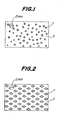
- the layer of the sealing material which forms a sheet at ordinary temperature is provided with small round section holes as shown in Fig. 1, through which upper and lower layers made of a vulcanized rubber composition are bonded.
- the sealing material layer is provided with rhombus section holes through which the upper and lower rubber composition layers are bonded.
- the rubber composition layer is provided with random cuts through which upper and lower rubber composition layers are bonded.
- strips made of a sealing material are laminated in a lattice fashion, and upper and lower rubber composition layers are bonded together through openings of the lattice.
- Fig. 1 small round section holes as shown in Fig. 1
- the sealing material layer is provided with rhombus section holes through which the upper and lower rubber composition layers are bonded.
- the rubber composition layer is provided with random cuts through which upper and lower rubber composition layers are bonded.
- strips made of a sealing material are laminated in a lattice fashion, and upper and lower rubber composition layers are bonded together through openings of the lattice.
- a sealing material layer is provided with slit-like holes through which upper and lower rubber composition layers are bonded.
- the slit-like bonding portions may be formed in a circumferential or radial direction of the tire, or in a direction forming a certain angle with respect to the tire circumferential direction. In order to prevent flowing of the sealing material in the tire radial direction, it is preferable to extend the bonding portions in the tire circumferential direction as in the case of Fig. 5.
- the bonding portion may have any shape. However, it is preferable that even when a circle having a diameter of 2 mm is drawn through any arbitrary location of the bonding portion, the bonding portion may contact the continuous sealing material layer within this circle. Thus, it is preferable to eliminate those bonding portions which do not contact with the continuous layer 2 at all within a circle having a diameter of 2 mm as shown in Fig. 7. 0n the contrary, when the sealing material layer between the vulcanizable rubber composition layers 3 is constituted by two or more sealing material layers as shown in Fig. 8, bonding portions 1 in one sealing material layer 2 may contain an imaginary circle having a diameter of more than 2 mm unless the bonding portions do not completely overlap between the layers.
- a tackifier may be incorporated into the sealing material layer.
- the layers of the vulcanizable rubber composition are arranged radially inside the inner surface of the carcass ply of the tire so that fatigue fracture resistance of the tire may not directly be lowered.
- the viscosity is set at not more than 6 ⁇ 104 poises at 60°C. It is preferable to select a material having fluidity at 10°c or more.
- the sealing material layer is continued in circumferential and axial directions between the vulcanizable rubber composition layers.
- the upper and lower layers made of a vulcanized rubber composition to enclose the sealing material layer are partially, discontinuously bonded together so as to ensure fatigue resistance of a composite body and to restrain staying of air in the sealing material layer.
- the sectional shape of the bonding portion is selected such that even when a circle having a diameter of 2 mm is drawn passing through any location of the bonding portion, the bonding portion contacts with the sealing material layer within this circle. Such is considered preferable, because even when a nail or the like enters the tire, it passes through the sealing material layer.
- the air-sealing member is constituted by this air-sealing material and the vulcanizable rubber composition layers holding the sealing material layer, and the sealing material layer is continued in the circumferential and axial directions.
- sealing material Even a single sealing material may be treated, during tire building, in the same manner as for ordinary tire-constituting members, if the sealing material has a viscosity of not less than 3 ⁇ 104 poises at ordinary temperature.
- the invention is more advantageous with respect to the heat generation characteristic and the fuel consumption rate.
- Passenger car tubeless radial tires having a size of 165 SR 13 shown in Fig. 9 were prepared under conditions given in Table 1 below.
- a vulcanized rubber composition to enclose layers 2 made of a sealing material in the present invention were disposed radially inside a carcass ply 4.
- Each of these test tires was fitted to a rear wheel of a vehicle, corroded nails having a diameter of 2 mm and a length of 33 mm were pierced into the tire at locations shown in Fig. 9.
- the nail-pierced tire was run on a circuit road having a turn distance of 3.5 km at average speed of 80 km/h.
- An air pressure was detected every three hours, and then running distance at which the initial internal pressure of 2.0 kg/cm2 was reduced to 1.0 kg/cm2 was presumed based on detected data.
- An air leakage-preventing rate when the nails were pulled out after the running is also given in Table 1.
- the air leakage-preventing rate is a percentage of the number of locations sealed to prevent air leakage with respect to the total number of all the locations where the nails were pierced into the tire.
- internal temperature of the tire was measured by a thermocouple inserted into a hole preliminarily bored in a central portion of a belt in a diameter of 2 mm after running on the circuit road for 1 hour. Above test results are shown in Table 1.
- Example 1 not provided Sealing material layer not enclosed with vulcanized rubber (conventional tire) Sealing material layer enclosed with vulcanized rubber Viscosity of sealing material at 60°C (poises) - 8 x 10⁴ 8 x 10⁴ 6 x 10⁴ 6 x 10⁴ Average gauge of sealing material at crown portion (mm) - 4.2 0.7 0.6 0.6 Width gauge of bonding portion (mm) - - 2 3 2 Temperature (°C) of tire 1 hour after running 63 67 64 64 64 64 Running distance when internal pressure dropped to 1 kg/cm2 (km) 1,225 1,465 1,350 1,800 2,400 Air leakage-preventing percentage (%) 0 60 40 90 95
- a syndiotactic 1,2-polybutadiene resin (manufactured by Japan Synthetic Rubber Co., Ltd., Trade name: RB resin (RB805)) and a liquid polyisoprene rubber (manufactured by Kuraray Co., Ltd. Trade name: LIR 50) were mixed, which was adjusted to a given viscosity and used as a sealing material in Table 1.
- Comparative Example 2 exhibited better results than Comparative Example 1 having no sealing material layer as a sealant, but was inferior to Examples 1 and 2 of the present invention with respect to the air-sealing performance. This is presumably because the sealing material collects at the tire equatorial plane during the running, and the sealing material less effectively acted with respect to the nails entering the shoulder portions. Further, Comparative Example 2 had a problem in that since the average gauge of the sealing material layer in Comparative Example 2 was greater, its heat generation of the tire was far greater than in Examples 1 and 2.
- Example 1 exhibited excellent effects with respect to both the running distance and the air leakage-preventing percentage in the state that the nails were pierced into the tire
- Example 2 exhibited better air-sealing effects.
- the present inventors dismantled the tire and made detailed examinations. Consequently, the inventors confirmed that four of all forty nails entered inside the tire without contacting the sealing material. That is, the bonding portion of the upper and lower layers were so great that the four nails completely passed therethrough.
- the pneumatic tire according to the present invention is more advantageous with respect to tire heat generation characteristic and fuel consumption rate, since (1) excellent air sealability is exhibited as compared with pneumatic tires provided with conventional adhesive rubber layers, (2) the sealing material can be treated in the same manner as an ordinary tire-constituting member during the tire building, and (3) the same effects as obtained in the conventional technique can be exhibited by using a smaller amount of the sealing material.
- the present invention is further to provide an effect to easily detect whether or not or where air leakage occurs in the tire by coloring the sealing material in a color different from that of the tire tread.
Landscapes
- Engineering & Computer Science (AREA)
- Mechanical Engineering (AREA)
- Tires In General (AREA)
- Heating, Cooling, Or Curing Plastics Or The Like In General (AREA)
Abstract
Description
- The present invention relates to pneumatic tires which can remarkably decrease the rate at which air leaks when a tire is punctured by a nail or the like.
- Heretofore, techniques have been known in which air leakage is prevented by providing an adhesive rubber layer on an inner surface of a tire, which rubber adheres to a nail or the like entering the tire (Japanese Patent Application Laid-open Nos. JP-A-55-11.998. 55-15.397. 60-64.834. etc.).
- However in such a conventional tire having an adhesive rubber layer provided on the tire inner surface since the inner surface of the adhesive layer is exposed to air, the layer deteriorates during use. Also, in order that the adhesive layer may attain its function at a place where the nail enters the tire, the thickness of the adhesive layer needs to be 3 to 5mm. Consequently the tire becomes heavy, so that fuel consumption rate and heat generation resistance are adversely affected. Furthermore since the adhesive layer accumulates near the equatorial plane of the tire due to centrifugal forces in the rotation of the tire or since the adhesive layer accumulates at one location during a prolonged period of non-use, it is difficult to maintain the adhesive layer in such a state that the adhesive layer can exhibit its effect wherever a nail enters the tire. In addition, a kneader and a coating system which are not normally required in a conventional tire production line are necessary for the production of such an adhesive layer.
- Under the circumstances, although conventional tires which are provided with an adhesive layer at the tire inner surface have certain air leakage-preventing effects, in practice such tires have rarely been commerically produced.
- The present invention aims to overcome or at least mitigate the above-mentioned problems, and to provide pneumatic tires in which air leakage is reduced while other tire performances are not significantly adversely affected.
- The present invention provides a pneumatic tire comprising a carcass ply, two vulcanized rubber composition layers arranged radially inside the carcass ply, a continuous layer of a sealing material arranged between the two vulcanized rubber composition layers, the sealing material having a viscosity of not more than 6 × 10⁴ poises at 60°C, and bonding portions discontinuously bonding the two vulcanized rubber composition layers, the bonding portions passing through the continuous layer.
- The invention will be further described by way of example only with reference to the accompanying drawings, wherein:
- Fig. 1 is a plan view illustrating a layer of a sealing material, which has small round section holes as portions for bonding upper and lower walls of vulcanized rubber composition layers;
- Figure. 2 is a plan view of a sealing material layer which has rhombus section holes as portions for bonding upper and lower walls of vulcanized rubber composition layers;
- Fig. 3 is a plan view illustrating a sealing material layer which has random cuts as portions for bonding upper and lower walls of vulcanized rubber composition layers;
- Fig. 4 is a plan view illustrating a sealing material layer formed by laminating strips made of the sealing material in a lattice fashion, in which openings formed therebetween constitute portions for bonding upper and lower walls of rubber composition layers;
- Fig. 5 is a plan view illustrating a sealing material layer which has slit-like holes as portions for bonding upper and lower walls of rubber composition layers;
- Figs. 6 and 7 are enlarged views of two examples of the bonding portions illustrated in Fig. 3;
- Fig. 8 is a sectional view of a pneumatic tire provided with two layers of a sealing material; and
- Fig. 9 is a partially sectional view of pneumatic tires used in Experiments described subsequently.
- The sealing material used for the sealing material layer in the present invention is mainly composed of at least one material selected from polyethylene, polypropylene, polybutadiene, polyisoprene, polyisoprene-butadiene copolymer, polystyrene-butadiene copolymer, butyl rubber, halogenated butyl rubber, acrylonitrile-butadiene copolymer, silicon rubber, and a thermoplastic resin. The sealing material has a viscosity of not more than 6 × 10⁴ poises at 60°C. When the sealing material is colored in a color different from that of a tire tread, judgment as to whether or not or where air leakage occurs can be made easy. For this purpose, the viscosity of the sealing material is preferably not more than 5 × 10³ poises at 60°C
- The sealing material is a material which forms a sheet (Viscosity: not less than 3 × 10⁴ poises) at room temperature. Thus, it is possible to treat the sealing material itself in the form of the sheet.
- The sectional shape of the bonding portion in the present invention is designed such that even when a circle having a diameter of 2 mm is drawn passing through any location of the bonding portion, the bonding portion contacts the continuous layer within this circle.
- More particularly, the following ways may be employed by way of example.
- That is, the layer of the sealing material which forms a sheet at ordinary temperature is provided with small round section holes as shown in Fig. 1, through which upper and lower layers made of a vulcanized rubber composition are bonded. As shown in Fig. 2, the sealing material layer is provided with rhombus section holes through which the upper and lower rubber composition layers are bonded. As shown in Fig. 3, the rubber composition layer is provided with random cuts through which upper and lower rubber composition layers are bonded. Alternatively, as shown in Fig. 4, strips made of a sealing material are laminated in a lattice fashion, and upper and lower rubber composition layers are bonded together through openings of the lattice. As shown in Fig. 5, a sealing material layer is provided with slit-like holes through which upper and lower rubber composition layers are bonded. The slit-like bonding portions may be formed in a circumferential or radial direction of the tire, or in a direction forming a certain angle with respect to the tire circumferential direction. In order to prevent flowing of the sealing material in the tire radial direction, it is preferable to extend the bonding portions in the tire circumferential direction as in the case of Fig. 5.
- That is, the bonding portion may have any shape. However, it is preferable that even when a circle having a diameter of 2 mm is drawn through any arbitrary location of the bonding portion, the bonding portion may contact the continuous sealing material layer within this circle. Thus, it is preferable to eliminate those bonding portions which do not contact with the
continuous layer 2 at all within a circle having a diameter of 2 mm as shown in Fig. 7. 0n the contrary, when the sealing material layer between the vulcanizablerubber composition layers 3 is constituted by two or more sealing material layers as shown in Fig. 8, bondingportions 1 in onesealing material layer 2 may contain an imaginary circle having a diameter of more than 2 mm unless the bonding portions do not completely overlap between the layers. - If necessary, a tackifier, a softener, a filler, etc. may be incorporated into the sealing material layer.
- In the present invention, the layers of the vulcanizable rubber composition are arranged radially inside the inner surface of the carcass ply of the tire so that fatigue fracture resistance of the tire may not directly be lowered. In order that the sealing material layer may possess fluidity during running of the tire, the viscosity is set at not more than 6 × 10⁴ poises at 60°C. It is preferable to select a material having fluidity at 10°c or more. The sealing material layer is continued in circumferential and axial directions between the vulcanizable rubber composition layers.
- The upper and lower layers made of a vulcanized rubber composition to enclose the sealing material layer are partially, discontinuously bonded together so as to ensure fatigue resistance of a composite body and to restrain staying of air in the sealing material layer. Preferably, the sectional shape of the bonding portion is selected such that even when a circle having a diameter of 2 mm is drawn passing through any location of the bonding portion, the bonding portion contacts with the sealing material layer within this circle. Such is considered preferable, because even when a nail or the like enters the tire, it passes through the sealing material layer.
- As mentioned above, according to the present invention, the air-sealing member is constituted by this air-sealing material and the vulcanizable rubber composition layers holding the sealing material layer, and the sealing material layer is continued in the circumferential and axial directions. By so constructing, even when the nail or the like enters the tire, the sealing material which is pressed with a tire internal pressure collects around the nail or the like, and seals the tire. The sealing material functions as if it is blood, while the vulcanized rubber composition layers do as if they are muscles.
- Even a single sealing material may be treated, during tire building, in the same manner as for ordinary tire-constituting members, if the sealing material has a viscosity of not less than 3 × 10⁴ poises at ordinary temperature.
- Furthermore, in the conventional technique, a great amount of an adhesive sealant is used at a portion of the tire where a nail or the like may enter by utilizing an internal pressure and capillary phenomenon. As compared with this, the same function can be obtained with a smaller amount of the sealant in the present invention. Therefore, the invention is more advantageous with respect to the heat generation characteristic and the fuel consumption rate.
- Passenger car tubeless radial tires having a size of 165 SR 13 shown in Fig. 9 were prepared under conditions given in Table 1 below. As shown in Fig. 9, a vulcanized rubber composition to enclose
layers 2 made of a sealing material in the present invention were disposed radially inside acarcass ply 4. - Each of these test tires was fitted to a rear wheel of a vehicle, corroded nails having a diameter of 2 mm and a length of 33 mm were pierced into the tire at locations shown in Fig. 9. The nail-pierced tire was run on a circuit road having a turn distance of 3.5 km at average speed of 80 km/h. An air pressure was detected every three hours, and then running distance at which the initial internal pressure of 2.0 kg/cm² was reduced to 1.0 kg/cm² was presumed based on detected data. An air leakage-preventing rate when the nails were pulled out after the running is also given in Table 1. The air leakage-preventing rate is a percentage of the number of locations sealed to prevent air leakage with respect to the total number of all the locations where the nails were pierced into the tire. In addition, internal temperature of the tire was measured by a thermocouple inserted into a hole preliminarily bored in a central portion of a belt in a diameter of 2 mm after running on the circuit road for 1 hour. Above test results are shown in Table 1.
Table 1 Sealing material layer Comparative Example 1 Comparative Example 2 Comparative Example 3 Example 1 Example 2 not provided Sealing material layer not enclosed with vulcanized rubber (conventional tire) Sealing material layer enclosed with vulcanized rubber Viscosity of sealing material at 60°C (poises) - 8 x 10⁴ 8 x 10⁴ 6 x 10⁴ 6 x 10⁴ Average gauge of sealing material at crown portion (mm) - 4.2 0.7 0.6 0.6 Width gauge of bonding portion (mm) - - 2 3 2 Temperature (°C) of tire 1 hour after running63 67 64 64 64 Running distance when internal pressure dropped to 1 kg/cm² (km) 1,225 1,465 1,350 1,800 2,400 Air leakage-preventing percentage (%) 0 60 40 90 95 - A syndiotactic 1,2-polybutadiene resin (manufactured by Japan Synthetic Rubber Co., Ltd., Trade name: RB resin (RB805)) and a liquid polyisoprene rubber (manufactured by Kuraray Co., Ltd. Trade name: LIR 50) were mixed, which was adjusted to a given viscosity and used as a sealing material in Table 1.
- As is clear from Table 1, Comparative Example 2 exhibited better results than Comparative Example 1 having no sealing material layer as a sealant, but was inferior to Examples 1 and 2 of the present invention with respect to the air-sealing performance. This is presumably because the sealing material collects at the tire equatorial plane during the running, and the sealing material less effectively acted with respect to the nails entering the shoulder portions. Further, Comparative Example 2 had a problem in that since the average gauge of the sealing material layer in Comparative Example 2 was greater, its heat generation of the tire was far greater than in Examples 1 and 2.
- In Comparative Example 3, since the viscosity of the sealing material was so high as compared with Examples 1 and 2, the sealing material did not collect around the nails, so that no air-sealing effect was exhibited.
- As shown in Table 1, although Example 1 exhibited excellent effects with respect to both the running distance and the air leakage-preventing percentage in the state that the nails were pierced into the tire, Example 2 exhibited better air-sealing effects. In order to clarify reasons therefor, the present inventors dismantled the tire and made detailed examinations. Consequently, the inventors confirmed that four of all forty nails entered inside the tire without contacting the sealing material. That is, the bonding portion of the upper and lower layers were so great that the four nails completely passed therethrough.
- On the other hand, judging from experiences of the inventors, nails having a diameter of less than 2 mm extremely seldom penetrate tires.
- As explained above, the pneumatic tire according to the present invention is more advantageous with respect to tire heat generation characteristic and fuel consumption rate, since (1) excellent air sealability is exhibited as compared with pneumatic tires provided with conventional adhesive rubber layers, (2) the sealing material can be treated in the same manner as an ordinary tire-constituting member during the tire building, and (3) the same effects as obtained in the conventional technique can be exhibited by using a smaller amount of the sealing material. The present invention is further to provide an effect to easily detect whether or not or where air leakage occurs in the tire by coloring the sealing material in a color different from that of the tire tread.
Claims (9)
Applications Claiming Priority (2)
| Application Number | Priority Date | Filing Date | Title |
|---|---|---|---|
| JP63031865A JPH01208207A (en) | 1988-02-16 | 1988-02-16 | Pneumatic tire |
| JP31865/88 | 1988-02-16 |
Publications (3)
| Publication Number | Publication Date |
|---|---|
| EP0329454A2 true EP0329454A2 (en) | 1989-08-23 |
| EP0329454A3 EP0329454A3 (en) | 1990-11-22 |
| EP0329454B1 EP0329454B1 (en) | 1994-06-15 |
Family
ID=12342942
Family Applications (1)
| Application Number | Title | Priority Date | Filing Date |
|---|---|---|---|
| EP89301532A Expired - Lifetime EP0329454B1 (en) | 1988-02-16 | 1989-02-16 | Pneumatic tires |
Country Status (5)
| Country | Link |
|---|---|
| US (1) | US4966213A (en) |
| EP (1) | EP0329454B1 (en) |
| JP (1) | JPH01208207A (en) |
| DE (1) | DE68916056T2 (en) |
| ES (1) | ES2057105T3 (en) |
Cited By (3)
| Publication number | Priority date | Publication date | Assignee | Title |
|---|---|---|---|---|
| WO2001038075A1 (en) * | 1999-11-24 | 2001-05-31 | Honda Giken Kogyo Kabushiki Kaisha | Sealant filling methods for sealant-containing tire and sealant-containing tire tube |
| EP1174290A4 (en) * | 2000-01-27 | 2005-07-06 | Honda Motor Co Ltd | Tubeless tire |
| EP1688239A1 (en) | 2005-01-28 | 2006-08-09 | The Goodyear Tire & Rubber Company | Method for extruding a puncture sealant and mounting on a tire |
Families Citing this family (21)
| Publication number | Priority date | Publication date | Assignee | Title |
|---|---|---|---|---|
| US5295525A (en) * | 1992-06-22 | 1994-03-22 | Michelin Recherche Et Technique S.A. | Puncture sealant formulation |
| US5824383A (en) * | 1996-10-25 | 1998-10-20 | The Goodyear Tire & Rubber Company | Methods of securing splices in curable rubber articles |
| JP3912636B2 (en) * | 1998-03-04 | 2007-05-09 | 本田技研工業株式会社 | Tire tube manufacturing equipment |
| US6194485B1 (en) | 1999-04-01 | 2001-02-27 | Bridgestone Corporation | Compounding process for achieving uniform, fine particle size dispersion of curing agents with minimal use of solvents |
| JP4511753B2 (en) * | 2001-03-09 | 2010-07-28 | 本田技研工業株式会社 | Sealant sealing device for tire tube with sealant |
| JP4511754B2 (en) * | 2001-03-09 | 2010-07-28 | 本田技研工業株式会社 | Sealant sealing device for tire tube with sealant |
| US6915826B2 (en) * | 2002-12-06 | 2005-07-12 | The Goodyear Tire & Rubber Company | Puncture sealing pneumatic tire |
| US20050113502A1 (en) * | 2003-11-21 | 2005-05-26 | Fitzharris Wall Jennifer E. | Pneumatic tire with built-in colored sealant layer |
| US7073550B2 (en) * | 2004-03-17 | 2006-07-11 | The Goodyear Tire & Rubber Company | Pneumatic tire having built-in colored sealant layer and preparation thereof |
| US20060169664A1 (en) * | 2004-12-28 | 2006-08-03 | Holopack International Corp. | Vial for filling a syringe |
| US20060254687A1 (en) * | 2005-05-11 | 2006-11-16 | Sandstrom Paul H | Pneumatic tire with built-in sealant containing pre-hydrophobated silica |
| US7674344B2 (en) * | 2005-08-26 | 2010-03-09 | The Goodyear Tire & Rubber Company | Pneumatic tire with depolymerized butyl rubber-based built-in sealant prepared with activated organoperoxide |
| US20080115872A1 (en) * | 2006-11-16 | 2008-05-22 | Paul Harry Sandstrom | Butyl rubber which contains organoperoxide and isobutyene adsorbing activated carbon, pneumatic tire with built-in sealant and method |
| US20080142138A1 (en) * | 2006-12-19 | 2008-06-19 | Joseph Alan Incavo | Tire sealant containing silica and depolymerized butyl rubber in the presence of organoperoxide and modifier |
| US20080302046A1 (en) * | 2007-06-06 | 2008-12-11 | Burgess William J | Form for aligning masonry materials |
| US8617333B2 (en) | 2007-09-20 | 2013-12-31 | The Goodyear Tire & Rubber Company | Pneumatic tire having built-in sealant layer and preparation thereof |
| US8316903B2 (en) * | 2007-10-01 | 2012-11-27 | The Goodyear Tire & Rubber Company | Pneumatic tire having built-in sealant layer and preparation thereof |
| US8156979B2 (en) | 2007-11-19 | 2012-04-17 | Joseph Alan Incavo | Tire with zoned built-in sealant layer |
| US20100154959A1 (en) * | 2008-12-23 | 2010-06-24 | Ramendra Nath Majumdar | Method and apparatus for building a tire having a puncture sealant |
| US8293049B2 (en) | 2009-12-02 | 2012-10-23 | The Goodyear Tire & Rubber Company | Tire sealant and tire with sealant containing silica and balanced organoperoxide depolymerized butyl rubber |
| US9421824B2 (en) | 2014-04-29 | 2016-08-23 | The Goodyear Tire & Rubber Company | Pneumatic tire with sealant layer |
Family Cites Families (16)
| Publication number | Priority date | Publication date | Assignee | Title |
|---|---|---|---|---|
| CA531490A (en) * | 1956-10-09 | Y. Connell Balfour | Self-sealing tire construction | |
| GB191415660A (en) * | 1914-06-30 | 1914-09-10 | David John Chappell | Means for Preventing the Deflation of Pneumatic Tyres when Punctured. |
| US1977281A (en) * | 1932-09-09 | 1934-10-16 | Gen Tire & Rubber Co | Inner tube and method of manufacture |
| NL90652C (en) * | 1938-10-13 | |||
| US2345200A (en) * | 1940-08-03 | 1944-03-28 | Us Rubber Co | Method of manufacture of inner tubes |
| US2332913A (en) * | 1940-10-10 | 1943-10-26 | Us Rubber Co | Method of manufacturing puncture sealing inner tubes |
| US2877819A (en) * | 1953-03-03 | 1959-03-17 | Seiberling Rubber Co | Puncture sealing pneumatic tire |
| US3444918A (en) * | 1967-04-24 | 1969-05-20 | True Car Value Inc | Self-sealing safety tire |
| US3563294A (en) * | 1968-07-02 | 1971-02-16 | Alex Chien | Puncture-sealing band |
| US4165403A (en) * | 1973-05-16 | 1979-08-21 | Alban Clarence F | Article employing inter-leaved elastic layers and inelastic sheets |
| US4171237A (en) * | 1975-09-22 | 1979-10-16 | The Firestone Tire & Rubber Company | Sealant laminates |
| US4140167A (en) * | 1976-08-20 | 1979-02-20 | The Firestone Tire & Rubber Company | Sealant laminates |
| FR2425335A1 (en) * | 1978-05-10 | 1979-12-07 | Michelin & Cie | PNEUMATIC CONTAINING A GASKET OF PERFORATION CLOSURE |
| FR2431379A1 (en) * | 1978-07-17 | 1980-02-15 | Michelin & Cie | TIRE WITH VULCANIZING SEALING COVERING IN CASE OF PRAYING |
| US4388261A (en) * | 1981-10-01 | 1983-06-14 | The General Tire & Rubber Company | Method for forming a compartmented puncture sealant package by co-extrusion |
| EP0135463A1 (en) * | 1983-08-15 | 1985-03-27 | The Goodyear Tire & Rubber Company | Self-sealing pneumatic tire and method of manufacturing same |
-
1988
- 1988-02-16 JP JP63031865A patent/JPH01208207A/en active Granted
-
1989
- 1989-02-14 US US07/310,105 patent/US4966213A/en not_active Expired - Fee Related
- 1989-02-16 EP EP89301532A patent/EP0329454B1/en not_active Expired - Lifetime
- 1989-02-16 ES ES89301532T patent/ES2057105T3/en not_active Expired - Lifetime
- 1989-02-16 DE DE68916056T patent/DE68916056T2/en not_active Expired - Fee Related
Cited By (6)
| Publication number | Priority date | Publication date | Assignee | Title |
|---|---|---|---|---|
| WO2001038075A1 (en) * | 1999-11-24 | 2001-05-31 | Honda Giken Kogyo Kabushiki Kaisha | Sealant filling methods for sealant-containing tire and sealant-containing tire tube |
| US6911104B1 (en) | 1999-11-24 | 2005-06-28 | Honda Giken Kogyo Kabushiki Kaisha | Sealant filling methods for sealant-containing tire and sealant-containing tire tube |
| CN1307041C (en) * | 1999-11-24 | 2007-03-28 | 本田技研工业株式会社 | Sealant filling method of sealant filled tire |
| EP1174290A4 (en) * | 2000-01-27 | 2005-07-06 | Honda Motor Co Ltd | Tubeless tire |
| EP1688239A1 (en) | 2005-01-28 | 2006-08-09 | The Goodyear Tire & Rubber Company | Method for extruding a puncture sealant and mounting on a tire |
| EP1688239B1 (en) * | 2005-01-28 | 2009-12-02 | The Goodyear Tire & Rubber Company | Method for making a tire with a built-in-sealant and tire obtained thereby |
Also Published As
| Publication number | Publication date |
|---|---|
| JPH055657B2 (en) | 1993-01-22 |
| DE68916056T2 (en) | 1994-12-01 |
| JPH01208207A (en) | 1989-08-22 |
| EP0329454B1 (en) | 1994-06-15 |
| DE68916056D1 (en) | 1994-07-21 |
| ES2057105T3 (en) | 1994-10-16 |
| US4966213A (en) | 1990-10-30 |
| EP0329454A3 (en) | 1990-11-22 |
Similar Documents
| Publication | Publication Date | Title |
|---|---|---|
| EP0329454B1 (en) | Pneumatic tires | |
| KR101416683B1 (en) | Self-sealing composition for a pneumatic object | |
| US4919183A (en) | Self sealing pneumatic tire | |
| KR101593722B1 (en) | Airtight and puncture-resistant multilayer elastomer laminate, and inflatable article | |
| KR102089270B1 (en) | Vehicle pneumatic tire | |
| KR100913936B1 (en) | Pneumatic tire | |
| US8646500B2 (en) | Multilayered gas-tight and anti-puncture laminate object including same | |
| KR101605924B1 (en) | Self-sealing thermoplastic elastomer composition, puncture-resistant airtight multilayer laminate and inflatable article | |
| US7037395B2 (en) | Pneumatic tire and method of manufacturing the sane | |
| US20110198009A1 (en) | Pneumatic Article Provided with a Self-Sealing Composition | |
| US2877819A (en) | Puncture sealing pneumatic tire | |
| EP1484199B1 (en) | Method of manufacturing a self-sealing tire | |
| JPH06270283A (en) | Pneumatic tire | |
| GB2146959A (en) | Self sealing pneumatic tire | |
| JP2781200B2 (en) | Method for manufacturing tire using precured tread | |
| EP1437239A1 (en) | Pneumatic tire | |
| US4183390A (en) | Puncture-sealing tire | |
| JPH045030A (en) | Pneumatic tire | |
| JP2002362118A (en) | Pneumatic tire and method of manufacturing the same | |
| JP2005001547A (en) | Tire | |
| EP2202093A1 (en) | Tire comprising a sealant layer | |
| JPH04286631A (en) | Pneumatic tire | |
| JP2002362119A (en) | Pneumatic tire | |
| JPS63212108A (en) | Tyre having puncture preventing layer | |
| CN1050519A (en) | tire |
Legal Events
| Date | Code | Title | Description |
|---|---|---|---|
| PUAI | Public reference made under article 153(3) epc to a published international application that has entered the european phase |
Free format text: ORIGINAL CODE: 0009012 |
|
| AK | Designated contracting states |
Kind code of ref document: A2 Designated state(s): DE ES FR GB IT LU |
|
| PUAL | Search report despatched |
Free format text: ORIGINAL CODE: 0009013 |
|
| AK | Designated contracting states |
Kind code of ref document: A3 Designated state(s): DE ES FR GB IT LU |
|
| 17P | Request for examination filed |
Effective date: 19910517 |
|
| 17Q | First examination report despatched |
Effective date: 19921008 |
|
| GRAA | (expected) grant |
Free format text: ORIGINAL CODE: 0009210 |
|
| AK | Designated contracting states |
Kind code of ref document: B1 Designated state(s): DE ES FR GB IT LU |
|
| ITF | It: translation for a ep patent filed | ||
| REF | Corresponds to: |
Ref document number: 68916056 Country of ref document: DE Date of ref document: 19940721 |
|
| ET | Fr: translation filed | ||
| REG | Reference to a national code |
Ref country code: ES Ref legal event code: FG2A Ref document number: 2057105 Country of ref document: ES Kind code of ref document: T3 |
|
| PGFP | Annual fee paid to national office [announced via postgrant information from national office to epo] |
Ref country code: GB Payment date: 19950207 Year of fee payment: 7 |
|
| PGFP | Annual fee paid to national office [announced via postgrant information from national office to epo] |
Ref country code: DE Payment date: 19950209 Year of fee payment: 7 |
|
| PGFP | Annual fee paid to national office [announced via postgrant information from national office to epo] |
Ref country code: FR Payment date: 19950210 Year of fee payment: 7 |
|
| PG25 | Lapsed in a contracting state [announced via postgrant information from national office to epo] |
Ref country code: LU Free format text: LAPSE BECAUSE OF NON-PAYMENT OF DUE FEES Effective date: 19950228 |
|
| PGFP | Annual fee paid to national office [announced via postgrant information from national office to epo] |
Ref country code: ES Payment date: 19950228 Year of fee payment: 7 |
|
| PLBE | No opposition filed within time limit |
Free format text: ORIGINAL CODE: 0009261 |
|
| STAA | Information on the status of an ep patent application or granted ep patent |
Free format text: STATUS: NO OPPOSITION FILED WITHIN TIME LIMIT |
|
| 26N | No opposition filed | ||
| PG25 | Lapsed in a contracting state [announced via postgrant information from national office to epo] |
Ref country code: GB Effective date: 19960216 |
|
| PG25 | Lapsed in a contracting state [announced via postgrant information from national office to epo] |
Ref country code: ES Free format text: LAPSE BECAUSE OF NON-PAYMENT OF DUE FEES Effective date: 19960217 |
|
| GBPC | Gb: european patent ceased through non-payment of renewal fee |
Effective date: 19960216 |
|
| PG25 | Lapsed in a contracting state [announced via postgrant information from national office to epo] |
Ref country code: FR Effective date: 19961031 |
|
| PG25 | Lapsed in a contracting state [announced via postgrant information from national office to epo] |
Ref country code: DE Effective date: 19961101 |
|
| REG | Reference to a national code |
Ref country code: FR Ref legal event code: ST |
|
| REG | Reference to a national code |
Ref country code: ES Ref legal event code: FD2A Effective date: 19990405 |
|
| PG25 | Lapsed in a contracting state [announced via postgrant information from national office to epo] |
Ref country code: IT Free format text: LAPSE BECAUSE OF NON-PAYMENT OF DUE FEES;WARNING: LAPSES OF ITALIAN PATENTS WITH EFFECTIVE DATE BEFORE 2007 MAY HAVE OCCURRED AT ANY TIME BEFORE 2007. THE CORRECT EFFECTIVE DATE MAY BE DIFFERENT FROM THE ONE RECORDED. Effective date: 20050216 |