EP0329287A2 - Méthode de commande de fluide ainsi que le dispositif - Google Patents
Méthode de commande de fluide ainsi que le dispositif Download PDFInfo
- Publication number
- EP0329287A2 EP0329287A2 EP89300594A EP89300594A EP0329287A2 EP 0329287 A2 EP0329287 A2 EP 0329287A2 EP 89300594 A EP89300594 A EP 89300594A EP 89300594 A EP89300594 A EP 89300594A EP 0329287 A2 EP0329287 A2 EP 0329287A2
- Authority
- EP
- European Patent Office
- Prior art keywords
- valve
- closure member
- ducting
- magnetic
- biassing
- Prior art date
- Legal status (The legal status is an assumption and is not a legal conclusion. Google has not performed a legal analysis and makes no representation as to the accuracy of the status listed.)
- Granted
Links
Images


Classifications
-
- F—MECHANICAL ENGINEERING; LIGHTING; HEATING; WEAPONS; BLASTING
- F16—ENGINEERING ELEMENTS AND UNITS; GENERAL MEASURES FOR PRODUCING AND MAINTAINING EFFECTIVE FUNCTIONING OF MACHINES OR INSTALLATIONS; THERMAL INSULATION IN GENERAL
- F16K—VALVES; TAPS; COCKS; ACTUATING-FLOATS; DEVICES FOR VENTING OR AERATING
- F16K31/00—Actuating devices; Operating means; Releasing devices
- F16K31/02—Actuating devices; Operating means; Releasing devices electric; magnetic
- F16K31/06—Actuating devices; Operating means; Releasing devices electric; magnetic using a magnet, e.g. diaphragm valves, cutting off by means of a liquid
- F16K31/08—Actuating devices; Operating means; Releasing devices electric; magnetic using a magnet, e.g. diaphragm valves, cutting off by means of a liquid using a permanent magnet
- F16K31/086—Actuating devices; Operating means; Releasing devices electric; magnetic using a magnet, e.g. diaphragm valves, cutting off by means of a liquid using a permanent magnet the magnet being movable and actuating a second magnet connected to the closing element
-
- Y—GENERAL TAGGING OF NEW TECHNOLOGICAL DEVELOPMENTS; GENERAL TAGGING OF CROSS-SECTIONAL TECHNOLOGIES SPANNING OVER SEVERAL SECTIONS OF THE IPC; TECHNICAL SUBJECTS COVERED BY FORMER USPC CROSS-REFERENCE ART COLLECTIONS [XRACs] AND DIGESTS
- Y10—TECHNICAL SUBJECTS COVERED BY FORMER USPC
- Y10S—TECHNICAL SUBJECTS COVERED BY FORMER USPC CROSS-REFERENCE ART COLLECTIONS [XRACs] AND DIGESTS
- Y10S141/00—Fluent material handling, with receiver or receiver coacting means
- Y10S141/01—Magnetic
-
- Y—GENERAL TAGGING OF NEW TECHNOLOGICAL DEVELOPMENTS; GENERAL TAGGING OF CROSS-SECTIONAL TECHNOLOGIES SPANNING OVER SEVERAL SECTIONS OF THE IPC; TECHNICAL SUBJECTS COVERED BY FORMER USPC CROSS-REFERENCE ART COLLECTIONS [XRACs] AND DIGESTS
- Y10—TECHNICAL SUBJECTS COVERED BY FORMER USPC
- Y10T—TECHNICAL SUBJECTS COVERED BY FORMER US CLASSIFICATION
- Y10T137/00—Fluid handling
- Y10T137/0318—Processes
- Y10T137/0402—Cleaning, repairing, or assembling
- Y10T137/0419—Fluid cleaning or flushing
-
- Y—GENERAL TAGGING OF NEW TECHNOLOGICAL DEVELOPMENTS; GENERAL TAGGING OF CROSS-SECTIONAL TECHNOLOGIES SPANNING OVER SEVERAL SECTIONS OF THE IPC; TECHNICAL SUBJECTS COVERED BY FORMER USPC CROSS-REFERENCE ART COLLECTIONS [XRACs] AND DIGESTS
- Y10—TECHNICAL SUBJECTS COVERED BY FORMER USPC
- Y10T—TECHNICAL SUBJECTS COVERED BY FORMER US CLASSIFICATION
- Y10T137/00—Fluid handling
- Y10T137/4238—With cleaner, lubrication added to fluid or liquid sealing at valve interface
- Y10T137/4245—Cleaning or steam sterilizing
- Y10T137/4266—Steam sterilizing
-
- Y—GENERAL TAGGING OF NEW TECHNOLOGICAL DEVELOPMENTS; GENERAL TAGGING OF CROSS-SECTIONAL TECHNOLOGIES SPANNING OVER SEVERAL SECTIONS OF THE IPC; TECHNICAL SUBJECTS COVERED BY FORMER USPC CROSS-REFERENCE ART COLLECTIONS [XRACs] AND DIGESTS
- Y10—TECHNICAL SUBJECTS COVERED BY FORMER USPC
- Y10T—TECHNICAL SUBJECTS COVERED BY FORMER US CLASSIFICATION
- Y10T137/00—Fluid handling
- Y10T137/7722—Line condition change responsive valves
- Y10T137/7837—Direct response valves [i.e., check valve type]
- Y10T137/7876—With external means for opposing bias
Definitions
- This invention relates to a fluid control device, in particular a non-return valve arrangement in a packaging machine.
- EP0090664A discloses a liquid packaging machine in which the dosing filler comprises upper and lower bellows tubes co-axial with each other and with a first, spring-biassed, non-return valve by way of which the upper bellows tube communicates with the lower bellows tube.
- the lower bellows tube communicates with a filling nozzle arranged co-axially beneath it and containing a second spring-biassed, non-return valve.
- the liquid is pumped through the filler by vertical reciprocation of the first non-return valve.
- the flushing medium can be steam, in which case the filler becomes full of gaseous matter.
- the product can be pumped through the filler, in which case the product may not be re-usable and the process of removal takes some time.
- the movable closure member of the valve comprises soft or hard magnetic material, or is connected to another member which is of soft or hard magnetic material. Disposed externally of the valve housing is either a permanent magnet movable between an active position in which it controls the closure member and an inactive position, or an electromagnet energisible to control the closure member.
- FR1106163 and DE 2234972A both disclose non-return valves biassed closed by springs and with electromagnets energisible to open the valve closure members.
- a method of utilizing ducting containing a non-return valve including biassing means biassing a valve closure member of said valve into a closed position, comprising forcing said valve closure member out of said closed position to an open position against the action of said biassing means by pressing production fluid in said ducting against said valve closure member, whereby said production fluid flows through the open valve; characterized by operating magnetic means disposed externally of said ducting to maintain said closure member in an open position against the action of said biassing means, and passing a cleaning fluid through said ducting and the open valve while said magnetic means maintains said closure member in the latter position.
- a method of utilizing ducting disposed at an angle to the horizontal and containing a non-return valve including biassing means biassing a valve closure member of said valve upwardly into a closed position, comprising forcing said closure member downwardly out of said closed position to an open position against the action of said biassing means by pressing liquid in said ducting against said closure member, whereby said liquid flows downwards through the open valve; substantially ceasing said pressing, whereby said closure member returns to said closed position under the action of said biassing means, characterized by later operating magnetic means disposed externally of said ducting to displace said closure member downwards out of said closed position into an open position against the action of said biassing means, whereby gaseous fluid downstream of said valve may rise through the open valve.
- apparatus comprising ducting; a non-return valve contained in said ducting, said valve comprising a valve closure member, biassing means biassing said closure member into a closed position, and magnetic portions; pumping means communicating with said ducting and serving to press production fluid against said closure member to force said closure member out of said closed position into an open position against the action of said biassing means, characterized by magnetic means disposed externally of said ducting and operable to influence said magnetic portions magnetically to maintain said closure member in an open position against the action of said biassing means.
- a filler for filling containers with a production fluid, said filler including ducting, a valve contained in said ducting, said valve including a valve closure member, characterized by magnetic means disposed externally of said ducting and operable to displace said valve closure member relative to said ducting.
- the valve shown in the Figures 1 and 2 is at a filling stage (see Figure 6) of an aseptic packaging machine (see Figure 5), in which cartons are filled aseptically with a liquid, such as milk.
- the valve includes a tubular casing 1 formed of non-magnetic material and sealingly connected coaxially to pipes 2 and 3 of the filler.
- the lower and outlet end of the casing 1 is formed with a coaxial annular shoulder 4 acting as a valve seat, co-operating with a valve closure member 5 fixed to a valve stem 6.
- the stem 6 is fixed at its upper end to a hub 7 of a centering spider 8 formed of non-magnetic material and movable with the closure member 5. Beneath the spider 8 is an abutment ring 9 fixed co-axially to the interior of the casing 1.
- a fixed spider 10 Spaced below the abutment ring 9 and also fixed coaxially to the interior of the casing 1 is a fixed spider 10 having a hub 11 closely encircling the stem 6.
- Distributed at regular angular intervals around the external periphery of the casing 1 are a plurality of horseshoe, permanent magnets 13 which are mounted in an external ring 14 coaxial with the casing 1 and inwardly of which are upper and lower pole rings 15 and 16.
- Inserted into the spokes of the spider 8 are iron nuts 17 which can be magnetically attracted to the pole rings 15 and 16.
- Figure 1 shows the condition of the parts 13 to 16 during production of filled cartons by the machine.
- the iron nuts 17 remain sufficiently out of the magnetic field between the rings 15 and 16, even when the spider 8 is abutting against the ring 9, that the valve means 5 to 8 can operate without any interference from the magnetic field.
- valve means 5 to 8 should be held at least partly open against the action of the spring 12.
- Figure 2 Such a condition, in which the valve is being held fully open, is shown in Figure 2, in which the nuts 17 are exposed to the concentrated magnetic flux between the pole rings 15 and 16. Thereby, the movable valve means 5 to 8 is held fully open.
- the assembly 13 to 16 is raised until the iron nuts 17 are magnetically attracted and displaced towards the gap between the rings 15 and 16, and then the assembly 13 to 16 is lowered to open the valve to the required degree.
- the assembly 13 to 16 and thus the magnetic field is then lowered, the abutment ring 9 prevents the iron nuts 17 from following the magnetic field, and the spring 12 displaces the spider 8 upwards.
- Figures 3 and 4 differs from the version shown in Figures 1 and 2 chiefly in that the pole rings 15 and 16 are omitted and the iron nuts 17 are replaced by short vertical iron rods 17′ totally cast into the spider 8, which is of plastics, and in that the assembly 13 and 14 during the production condition is in an uppermost position indicated in dot-dash lines at 13′ in Figure 3.
- Figure 3 shows in full lines the position of the assembly 13 and 14 with the rods 17′ spanning the limbs of the horseshoe magnets 13 and with the valve closure member 5 about to be lowered, and thus opened, by lowering of the assembly.
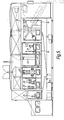
- the packaging machine is almost totally enclosed in a housing 18 with openable air-tight transparent windows 19 through which can be seen a bottom closure forming-and sealing - device 20, a top closure breaker 21, a sterile air inlet 22, the filler 23, a top closure heater 24, a top closure sealer 25, and a discharge 26.
- the filler 23 includes a reservoir 27 for liquid product and ducts 28 leading to respective metering pumps 29 whence respective ducts 30 lead to respective filling nozzles 31.
- the ducts 28 contain respective valve devices not seen, but each as described with reference to Figures 1 and 2, or Figures 3 and 4.
- the rings 14 of the respective valve devices are interconnected by a yoke 32 which can be raised and lowered, to raise and lower the rings 14, by a pneumatic piston-and-cylinder device (not shown) through a linkage 33.
- valve device described with reference to the drawings is that there is no mechanical control connection from externally to internally of the valve housing, so reducing sealing problems and cleaning problems, and thus reducing the risks of contamination of the product.
- a DC electromagnetic coil could be used.
Landscapes
- Engineering & Computer Science (AREA)
- General Engineering & Computer Science (AREA)
- Mechanical Engineering (AREA)
- Filling Of Jars Or Cans And Processes For Cleaning And Sealing Jars (AREA)
- Gas Exhaust Devices For Batteries (AREA)
- Hydraulic Clutches, Magnetic Clutches, Fluid Clutches, And Fluid Joints (AREA)
- Supply Of Fluid Materials To The Packaging Location (AREA)
- Basic Packing Technique (AREA)
- Fluid-Pressure Circuits (AREA)
Applications Claiming Priority (2)
| Application Number | Priority Date | Filing Date | Title |
|---|---|---|---|
| GB888801665A GB8801665D0 (en) | 1988-01-26 | 1988-01-26 | Fluid control device |
| GB8801665 | 1988-01-26 |
Publications (3)
| Publication Number | Publication Date |
|---|---|
| EP0329287A2 true EP0329287A2 (fr) | 1989-08-23 |
| EP0329287A3 EP0329287A3 (fr) | 1991-04-24 |
| EP0329287B1 EP0329287B1 (fr) | 1994-08-31 |
Family
ID=10630522
Family Applications (1)
| Application Number | Title | Priority Date | Filing Date |
|---|---|---|---|
| EP89300594A Expired - Lifetime EP0329287B1 (fr) | 1988-01-26 | 1989-01-23 | Méthode de commande de fluide ainsi que le dispositif |
Country Status (7)
| Country | Link |
|---|---|
| US (1) | US5069239A (fr) |
| EP (1) | EP0329287B1 (fr) |
| JP (1) | JP2990518B2 (fr) |
| AT (1) | ATE110831T1 (fr) |
| DE (1) | DE68917751T2 (fr) |
| ES (1) | ES2058488T3 (fr) |
| GB (1) | GB8801665D0 (fr) |
Cited By (6)
| Publication number | Priority date | Publication date | Assignee | Title |
|---|---|---|---|---|
| FR2705753A1 (fr) * | 1993-05-28 | 1994-12-02 | Serac Sa | Vanne à commande magnétique. |
| AU655812B2 (en) * | 1991-04-29 | 1995-01-12 | David Ronald Leat | Improved valve apparatus |
| FR2736412A1 (fr) * | 1995-07-05 | 1997-01-10 | Serac Group | Dispositif de commande magnetique d'un organe d'obturation dans un corps tubulaire et bec de remplissage a debit variable comportant un tel dispositif |
| WO2005040656A1 (fr) | 2003-10-22 | 2005-05-06 | Elopak Systems Ag | Dispositif formant clapet pour reguler un ecoulement fluidique et procede correspondant |
| FR2881500A1 (fr) * | 2005-02-01 | 2006-08-04 | Clesse Ind Soc Par Actions Sim | Robinet a obturation automatique integree |
| WO2012069236A1 (fr) * | 2010-11-26 | 2012-05-31 | Robert Bosch Gmbh | Soupape comportant un élément mobile cylindrique au moins par tronçons |
Families Citing this family (9)
| Publication number | Priority date | Publication date | Assignee | Title |
|---|---|---|---|---|
| IL127901A (en) * | 1999-01-01 | 2001-06-14 | Gilad Shimon | Non-return valve |
| US6648012B2 (en) * | 2001-06-13 | 2003-11-18 | Applied Materials, Inc. | Non-return valve override device |
| GB0205878D0 (en) * | 2002-03-13 | 2002-04-24 | British Nuclear Fuels Plc | Valve |
| US7171981B2 (en) * | 2004-07-02 | 2007-02-06 | Watersav Enterprises, Llc | Flow control device and system |
| US7278443B2 (en) * | 2004-12-16 | 2007-10-09 | Diversified Dynamics Corporation | Pulsation causing valve for a plural piston pump |
| US7290561B2 (en) * | 2004-12-16 | 2007-11-06 | Diversified Dynamics Corporation | Pulsation causing valve for a plural piston pump |
| US8464998B2 (en) * | 2006-09-22 | 2013-06-18 | Advanced Modern Technologies Corporation | Automate fluid flow control system |
| ITBO20130699A1 (it) * | 2013-12-20 | 2015-06-21 | Marchesini Group Spa | Apparato per iniettare una quantita' dosata di liquido medicinale all'interno di un flacone |
| EP3165500A1 (fr) * | 2015-11-06 | 2017-05-10 | Sidel Participations | Soupape de régulation de débit pour une machine de remplissage |
Citations (2)
| Publication number | Priority date | Publication date | Assignee | Title |
|---|---|---|---|---|
| DE2234972A1 (de) * | 1971-07-28 | 1973-02-08 | Cafe Bar Internal Pty Ltd | Spender fuer pulverfoermige stoffe |
| DE3515848A1 (de) * | 1985-05-02 | 1986-11-06 | Siemens AG, 1000 Berlin und 8000 München | Ventil fuer ein medikamentendosiergeraet |
Family Cites Families (20)
| Publication number | Priority date | Publication date | Assignee | Title |
|---|---|---|---|---|
| US2698120A (en) * | 1951-06-22 | 1954-12-28 | Lindley W Potts | Process and apparatus for sterilizing and filling containers |
| FR1106163A (fr) * | 1954-08-03 | 1955-12-13 | électro-vanne pour corps liquides ou gazeux | |
| US2845099A (en) * | 1956-09-17 | 1958-07-29 | Rauland Corp | Screening dispenser for cathode-ray tube manufacturing apparatus |
| FR86078E (fr) * | 1964-05-13 | 1965-12-03 | Source Perrier | Robinet à soupape perfectionné pour le remplissage de bouteilles avec des boissons et plus spécialement avec des boissons gazeuses à forte teneur en pulpe |
| US3500880A (en) * | 1966-10-24 | 1970-03-17 | Automatic Sprinkler Corp | Container filling apparatus |
| CH497899A (de) * | 1967-12-20 | 1970-10-31 | Hansen Gerhard | Verfahren und Vorrichtung für das Sterilisieren einer Maschine zum Herstellen, Füllen und Verschliessen eines Kunststoffbehälters |
| US3513024A (en) * | 1968-01-19 | 1970-05-19 | Diversey Corp | Method for cleaning automatic liquid filling machine valves |
| US3774655A (en) * | 1971-06-21 | 1973-11-27 | W Trusselle | Container-filling apparatus |
| JPS50119325A (fr) * | 1974-02-26 | 1975-09-18 | ||
| CA1101397A (fr) * | 1978-03-06 | 1981-05-19 | Kunio Shimizu | Dispositif de coupure de la circulation d'un fluide |
| GB2021237A (en) * | 1978-05-17 | 1979-11-28 | Agfa Gevaert | Flow control valve |
| DE3027351A1 (de) * | 1979-07-19 | 1981-02-12 | Tetsuichi Imai | Magnetischer antriebsmechanismus und magnetisch betaetigte durchflussventile |
| US4349042A (en) * | 1980-07-28 | 1982-09-14 | Kunio Shimizu | Fluid shut-off device |
| JPS6058390A (ja) * | 1983-08-27 | 1985-04-04 | 澁谷工業株式会社 | 充填装置 |
| US4631923A (en) * | 1983-10-21 | 1986-12-30 | Devron Engineering Limited | Solenoid operated check valve |
| JPS60228290A (ja) * | 1984-04-25 | 1985-11-13 | 株式会社日立製作所 | 薬液充填装置 |
| JPS6133919A (ja) * | 1984-07-16 | 1986-02-18 | 四国化工機株式会社 | 液体充てん装置における充てんノズルの洗浄殺菌装置 |
| JPS61104906A (ja) * | 1984-10-25 | 1986-05-23 | 東和製機株式会社 | 充填ノズル |
| JPS62110086A (ja) * | 1985-11-06 | 1987-05-21 | Toshiba Corp | 二重管電磁弁 |
| US4716921A (en) * | 1986-04-14 | 1988-01-05 | Ex-Cell-O Corporation | Filler sterilization system |
-
1988
- 1988-01-26 GB GB888801665A patent/GB8801665D0/en active Pending
-
1989
- 1989-01-23 AT AT89300594T patent/ATE110831T1/de not_active IP Right Cessation
- 1989-01-23 EP EP89300594A patent/EP0329287B1/fr not_active Expired - Lifetime
- 1989-01-23 ES ES89300594T patent/ES2058488T3/es not_active Expired - Lifetime
- 1989-01-23 DE DE68917751T patent/DE68917751T2/de not_active Expired - Fee Related
- 1989-01-25 JP JP1014235A patent/JP2990518B2/ja not_active Expired - Fee Related
-
1991
- 1991-05-10 US US07/708,772 patent/US5069239A/en not_active Expired - Lifetime
Patent Citations (2)
| Publication number | Priority date | Publication date | Assignee | Title |
|---|---|---|---|---|
| DE2234972A1 (de) * | 1971-07-28 | 1973-02-08 | Cafe Bar Internal Pty Ltd | Spender fuer pulverfoermige stoffe |
| DE3515848A1 (de) * | 1985-05-02 | 1986-11-06 | Siemens AG, 1000 Berlin und 8000 München | Ventil fuer ein medikamentendosiergeraet |
Cited By (11)
| Publication number | Priority date | Publication date | Assignee | Title |
|---|---|---|---|---|
| AU655812B2 (en) * | 1991-04-29 | 1995-01-12 | David Ronald Leat | Improved valve apparatus |
| FR2705753A1 (fr) * | 1993-05-28 | 1994-12-02 | Serac Sa | Vanne à commande magnétique. |
| EP0627585A1 (fr) * | 1993-05-28 | 1994-12-07 | Serac France | Vanne à commande magnétique |
| US5450877A (en) * | 1993-05-28 | 1995-09-19 | Serac | Magnetically-controlled valve |
| FR2736412A1 (fr) * | 1995-07-05 | 1997-01-10 | Serac Group | Dispositif de commande magnetique d'un organe d'obturation dans un corps tubulaire et bec de remplissage a debit variable comportant un tel dispositif |
| WO1997002180A1 (fr) * | 1995-07-05 | 1997-01-23 | Serac Group | Bec de remplissage et vanne a commande magnetique |
| US5676344A (en) * | 1995-07-05 | 1997-10-14 | Serac Group | Device for magnetically controlling a shutter member in a tubular body, and a variable flow rate filler spout including such a device |
| WO2005040656A1 (fr) | 2003-10-22 | 2005-05-06 | Elopak Systems Ag | Dispositif formant clapet pour reguler un ecoulement fluidique et procede correspondant |
| FR2881500A1 (fr) * | 2005-02-01 | 2006-08-04 | Clesse Ind Soc Par Actions Sim | Robinet a obturation automatique integree |
| WO2012069236A1 (fr) * | 2010-11-26 | 2012-05-31 | Robert Bosch Gmbh | Soupape comportant un élément mobile cylindrique au moins par tronçons |
| US9249893B2 (en) | 2010-11-26 | 2016-02-02 | Robert Bosch Gmbh | Valve device having a movement element which is cylindrical at least in sections |
Also Published As
| Publication number | Publication date |
|---|---|
| JPH01254595A (ja) | 1989-10-11 |
| DE68917751D1 (de) | 1994-10-06 |
| US5069239A (en) | 1991-12-03 |
| DE68917751T2 (de) | 1994-12-22 |
| EP0329287B1 (fr) | 1994-08-31 |
| ATE110831T1 (de) | 1994-09-15 |
| EP0329287A3 (fr) | 1991-04-24 |
| JP2990518B2 (ja) | 1999-12-13 |
| ES2058488T3 (es) | 1994-11-01 |
| GB8801665D0 (en) | 1988-02-24 |
Similar Documents
| Publication | Publication Date | Title |
|---|---|---|
| EP0329287B1 (fr) | Méthode de commande de fluide ainsi que le dispositif | |
| JP5037602B2 (ja) | 充填要素と充填要素を備える充填機 | |
| EP0436214B1 (fr) | Valve de remplissage aseptique | |
| US5450877A (en) | Magnetically-controlled valve | |
| EP1310454B1 (fr) | Bec de remplissage pour machine d'embouteillage | |
| US3583426A (en) | Aseptically sealing valve | |
| US10370234B2 (en) | Filling device for filling machine | |
| EP2881636B1 (fr) | Soupape fournie avec un actionneur magnétique | |
| JP5068751B2 (ja) | 三位置バルブロッドを有する充填バルブ | |
| CN105565234A (zh) | 容器填充系统和用于容器填充系统的阀 | |
| US11148924B2 (en) | Filling valve and filling machine for filling receptacles | |
| RU1838705C (ru) | Установка дл взаимодействи с потоком | |
| EP3543205A1 (fr) | Soupape de remplissage, machine de remplissage et procédé pour remplir des récipients | |
| EP0593217B1 (fr) | Système de remplissage de cartons | |
| US5676344A (en) | Device for magnetically controlling a shutter member in a tubular body, and a variable flow rate filler spout including such a device | |
| EP3473590A1 (fr) | Dispositif de remplissage amélioré pour une machine de remplissage | |
| WO1999039978A1 (fr) | Ensemble clapet servant a effectuer un remplissage dans des conditions aseptiques | |
| EP0541945B1 (fr) | Pompe à tube vibrante | |
| US5897304A (en) | Flow-through vertical filling pump with a plurality of diaphragms | |
| US10538423B2 (en) | Filling system and filling packages | |
| US6941986B2 (en) | Device for aseptically filling containers | |
| CN1871470A (zh) | 控制液流的阀装置和方法 | |
| JP2007510100A5 (fr) | ||
| US3430668A (en) | Container filling machine head | |
| WO2023208605A1 (fr) | Dispositif de remplissage permettant de remplir des contenants avec un produit pouvant être versé |
Legal Events
| Date | Code | Title | Description |
|---|---|---|---|
| PUAI | Public reference made under article 153(3) epc to a published international application that has entered the european phase |
Free format text: ORIGINAL CODE: 0009012 |
|
| AK | Designated contracting states |
Kind code of ref document: A2 Designated state(s): AT BE CH DE ES FR GB IT LI LU NL SE |
|
| PUAL | Search report despatched |
Free format text: ORIGINAL CODE: 0009013 |
|
| AK | Designated contracting states |
Kind code of ref document: A3 Designated state(s): AT BE CH DE ES FR GB IT LI LU NL SE |
|
| RHK1 | Main classification (correction) |
Ipc: F16K 15/18 |
|
| 17P | Request for examination filed |
Effective date: 19910620 |
|
| 17Q | First examination report despatched |
Effective date: 19930405 |
|
| GRAA | (expected) grant |
Free format text: ORIGINAL CODE: 0009210 |
|
| AK | Designated contracting states |
Kind code of ref document: B1 Designated state(s): AT BE CH DE ES FR GB IT LI LU NL SE |
|
| REF | Corresponds to: |
Ref document number: 110831 Country of ref document: AT Date of ref document: 19940915 Kind code of ref document: T |
|
| ITF | It: translation for a ep patent filed |
Owner name: BUGNION S.P.A. |
|
| REF | Corresponds to: |
Ref document number: 68917751 Country of ref document: DE Date of ref document: 19941006 |
|
| REG | Reference to a national code |
Ref country code: ES Ref legal event code: FG2A Ref document number: 2058488 Country of ref document: ES Kind code of ref document: T3 |
|
| ET | Fr: translation filed | ||
| EAL | Se: european patent in force in sweden |
Ref document number: 89300594.2 |
|
| PG25 | Lapsed in a contracting state [announced via postgrant information from national office to epo] |
Ref country code: LU Free format text: LAPSE BECAUSE OF NON-PAYMENT OF DUE FEES Effective date: 19950131 |
|
| PLBE | No opposition filed within time limit |
Free format text: ORIGINAL CODE: 0009261 |
|
| STAA | Information on the status of an ep patent application or granted ep patent |
Free format text: STATUS: NO OPPOSITION FILED WITHIN TIME LIMIT |
|
| 26N | No opposition filed | ||
| REG | Reference to a national code |
Ref country code: GB Ref legal event code: IF02 |
|
| PGFP | Annual fee paid to national office [announced via postgrant information from national office to epo] |
Ref country code: FR Payment date: 20041209 Year of fee payment: 17 |
|
| PGFP | Annual fee paid to national office [announced via postgrant information from national office to epo] |
Ref country code: AT Payment date: 20041210 Year of fee payment: 17 |
|
| PGFP | Annual fee paid to national office [announced via postgrant information from national office to epo] |
Ref country code: NL Payment date: 20041213 Year of fee payment: 17 Ref country code: GB Payment date: 20041213 Year of fee payment: 17 |
|
| PGFP | Annual fee paid to national office [announced via postgrant information from national office to epo] |
Ref country code: DE Payment date: 20041214 Year of fee payment: 17 Ref country code: CH Payment date: 20041214 Year of fee payment: 17 |
|
| PGFP | Annual fee paid to national office [announced via postgrant information from national office to epo] |
Ref country code: SE Payment date: 20041220 Year of fee payment: 17 |
|
| PGFP | Annual fee paid to national office [announced via postgrant information from national office to epo] |
Ref country code: ES Payment date: 20050113 Year of fee payment: 17 |
|
| PG25 | Lapsed in a contracting state [announced via postgrant information from national office to epo] |
Ref country code: IT Free format text: LAPSE BECAUSE OF NON-PAYMENT OF DUE FEES Effective date: 20050123 |
|
| PGFP | Annual fee paid to national office [announced via postgrant information from national office to epo] |
Ref country code: BE Payment date: 20050125 Year of fee payment: 17 |
|
| PG25 | Lapsed in a contracting state [announced via postgrant information from national office to epo] |
Ref country code: GB Free format text: LAPSE BECAUSE OF NON-PAYMENT OF DUE FEES Effective date: 20060123 Ref country code: AT Free format text: LAPSE BECAUSE OF NON-PAYMENT OF DUE FEES Effective date: 20060123 |
|
| PG25 | Lapsed in a contracting state [announced via postgrant information from national office to epo] |
Ref country code: SE Free format text: LAPSE BECAUSE OF NON-PAYMENT OF DUE FEES Effective date: 20060124 Ref country code: ES Free format text: LAPSE BECAUSE OF NON-PAYMENT OF DUE FEES Effective date: 20060124 |
|
| PG25 | Lapsed in a contracting state [announced via postgrant information from national office to epo] |
Ref country code: LI Free format text: LAPSE BECAUSE OF NON-PAYMENT OF DUE FEES Effective date: 20060131 Ref country code: FR Free format text: LAPSE BECAUSE OF NON-PAYMENT OF DUE FEES Effective date: 20060131 Ref country code: CH Free format text: LAPSE BECAUSE OF NON-PAYMENT OF DUE FEES Effective date: 20060131 Ref country code: BE Free format text: LAPSE BECAUSE OF NON-PAYMENT OF DUE FEES Effective date: 20060131 |
|
| PG25 | Lapsed in a contracting state [announced via postgrant information from national office to epo] |
Ref country code: NL Free format text: LAPSE BECAUSE OF NON-PAYMENT OF DUE FEES Effective date: 20060801 Ref country code: DE Free format text: LAPSE BECAUSE OF NON-PAYMENT OF DUE FEES Effective date: 20060801 |
|
| REG | Reference to a national code |
Ref country code: CH Ref legal event code: PL |
|
| EUG | Se: european patent has lapsed | ||
| GBPC | Gb: european patent ceased through non-payment of renewal fee |
Effective date: 20060123 |
|
| NLV4 | Nl: lapsed or anulled due to non-payment of the annual fee |
Effective date: 20060801 |
|
| REG | Reference to a national code |
Ref country code: FR Ref legal event code: ST Effective date: 20060929 |
|
| REG | Reference to a national code |
Ref country code: ES Ref legal event code: FD2A Effective date: 20060124 |
|
| BERE | Be: lapsed |
Owner name: *ELOPAK SYSTEMS A.G. Effective date: 20060131 |