EP0329202A2 - Vorrichtung zum Einlegen von Spulenhülsen - Google Patents
Vorrichtung zum Einlegen von Spulenhülsen Download PDFInfo
- Publication number
- EP0329202A2 EP0329202A2 EP89106775A EP89106775A EP0329202A2 EP 0329202 A2 EP0329202 A2 EP 0329202A2 EP 89106775 A EP89106775 A EP 89106775A EP 89106775 A EP89106775 A EP 89106775A EP 0329202 A2 EP0329202 A2 EP 0329202A2
- Authority
- EP
- European Patent Office
- Prior art keywords
- bobbin
- gripper
- cradle
- yarn
- path
- Prior art date
- Legal status (The legal status is an assumption and is not a legal conclusion. Google has not performed a legal analysis and makes no representation as to the accuracy of the status listed.)
- Granted
Links
Images


Classifications
-
- B—PERFORMING OPERATIONS; TRANSPORTING
- B65—CONVEYING; PACKING; STORING; HANDLING THIN OR FILAMENTARY MATERIAL
- B65H—HANDLING THIN OR FILAMENTARY MATERIAL, e.g. SHEETS, WEBS, CABLES
- B65H67/00—Replacing or removing cores, receptacles, or completed packages at paying-out, winding, or depositing stations
- B65H67/04—Arrangements for removing completed take-up packages and or replacing by cores, formers, or empty receptacles at winding or depositing stations; Transferring material between adjacent full and empty take-up elements
- B65H67/0405—Arrangements for removing completed take-up packages or for loading an empty core
- B65H67/0417—Arrangements for removing completed take-up packages or for loading an empty core for loading an empty core
-
- B—PERFORMING OPERATIONS; TRANSPORTING
- B65—CONVEYING; PACKING; STORING; HANDLING THIN OR FILAMENTARY MATERIAL
- B65H—HANDLING THIN OR FILAMENTARY MATERIAL, e.g. SHEETS, WEBS, CABLES
- B65H2701/00—Handled material; Storage means
- B65H2701/30—Handled filamentary material
- B65H2701/31—Textiles threads or artificial strands of filaments
Definitions
- the present invention relates to improvements in travelling service tenders for yarn handling machines of the type having a plurality of operating stations each including a yarn wind-up apparatus comprising a friction drive roll and a cradle means for holding a bobbin tube/yarn package in contact with the friction drive roll during formation of a yarn package on the bobbin tube.
- Such machines include, in particular but not exclusively, rotor spinning machines; other examples include automatic rewinders for rewinding cops into cross-wound packages and false twist texturising machines.
- examples of the type of wind-up mechanism involved can be seen from the following patent specifications-German 2649156, US 3356306 and GB 1399891.
- the incoming bobbin tube should be transferred from the bobbin inserting device to the cradle mechanism at an intermediate position on the arc of swing of the cradle mechanism such that the bobbin tube is not then in contact with the friction drive roll.
- This enables temporary insertion of transmission rollers between the friction drive roll and the incoming bobbin tube, so that the tube can be rotated at a speed lower than the normal winding speed during formation of a thread reserve.
- the final stage of movement between the intermediate position and the normal winding position is effected only by movement of the cradle mechan ism, the bobbin inserting device being withdrawn from contact with the bobbin tube.
- the bobbin diameter can vary substantially depending upon the requirements of the end-user of the yarn handling machine.
- the diameters of bobbins used on current open-end spinning machines can vary between approximately 60 mm and 105 mm.
- the bobbin inserting device may comprise a bobbin gripper movable along a fixed path of movement, and the inserting device may be associated with a bobbin holder adapted to present a bobbin to the gripper.
- the bobbin holder may be adaptable to locate bobbins of varying diameters relative to the fixed path of movement of the gripper.
- the fixed path of movement may be capable of arrangement relative to an operating station of a yarn-handling machine to define a transfer location at which a bobbin carried by the gripper is inserted into a cradle mechanism at that station.
- the transfer location may be such that, at least for smaller diameter bobbins, an inserted bobbin is moved by the cradle mechanism from the transfer position to a winding position in which the bobbin contacts the friction drive roll of the relevant operating station.
- the present bobbin inserting device may comprise a carrier member carrying the bobbin gripper and movable to move the bobbin gripper along its bobbin insertion path.
- the carrier member may be further movable to move the bobbin gripper to hold an inserted bobbin in the winding position to which it has been moved by the cradle mechanism.
- the bobbin gripper may be adjustably mounted on the carrier member.
- the cradle mechanism may then be releasable after the bobbin is located in the winding position to enable clamping of the yarn between the cradle mechanism and the inserted bobbin.
- the gripper is adapted to urge the bobbin against a part of the cradle mechanism after the release of the latter; this feature enables continued axial location of the bobbin and simultaneous angular location of the cradle.
- selectively operable control means are provided to control feed of bobbins to a collection location for collection by the bobbin insertion device.
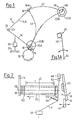
- Fig. 1 shows in diagrammatic side elevation a friction drive roll 10 and a bobbin cradle mechanism generally indicated by the numeral 12.
- the cradle mechanism comprises a pair of arms 14, 16 which are aligned with one another as viewed in Fig. 1 so that only the nearer arm 14 is fully visible in that figure.
- Arm 16 is slightly longer than arm 14 so that its end portion can be seen in Fig. 1.
- Each arm carries a respective centering plate 18, 20 (better seen in Fig. 2) which in use carry between them a cylindrical bobbin tube 22.
- Arms 14, 16 are carried by a carrier 23 (Fig. 1) which is pivotable about a bearing element 24 mounted in the machine structure. Arm 14 is fixed to the carrier, but arm 16 is pivotally mounted thereon for movement towards and away from the arm 14 as indicated by the double-headed arrow B in Fig. 2. Arm 16 has a normal position approximately parallel to arm 14 such that bobbin tube 22 is clamped between the plates 18 and 20. However, when arm 16 is pivoted away from arm 14 as shown in Fig. 2, a space is made for release of a yarn package formed on the bobbin tube 22 and/or insertion of a fresh bobbin tube between the centering plates.
- Cradle mechanism 12 further comprises a cradle loading device 28 (Fig. 1).
- Device 28 is fixed at one end to the machine structure 26 and at the other end to the cradle comprising carrier 23 and arms 14, 16.
- the loading device includes a biasing means (usually a spring- weighted device) which normally tends to draws the arms 14, 16 downwardly as viewed in Fig. 1 into a winding position in which a bobbin tube 22 carried by the arms engages the friction roll 10.
- Roll 10 is driven into rotation about its own longitudinal axis as indicated by the arrow in Fig. 1, and the plates 18, 20 are rotatable about axis 19 on the arms 14, 16 so that the bobbin tube 22 is rotated by frictional engagement with the roll 10.
- the devices required to perform these operations automatically may be provided at the individual spinning stations, but for economic reasons it is preferred to provide a service tender which is provided with one set of ejection/insertion devices and which is movable longitudinally of the machine past the stations. Means is provided to locate the tender in alignment with any selected station in order to enable performance of ejection/insertion operations thereon.
- a service tender will be assumed, but it will be apparent that the principles described could also be applied to multiple ejection/insertion devices.
- Bobbin insertion is commonly effected by means of a bobbin gripper 30 (Fig. 1A) mounted at the end of an arm 32 which is pivotable about a pivot mounting 34 in the service tender.
- the gripper collects a bobbin from a bobbin holder (not shown) in an upper portion of its swinging movement about the mounting 34, and then moves the bobbin to a position at which the bobbin can be transferred to the cradle mechanism 12.
- the bobbin holder may be on the service tender or on the machine, but in the latter case one bobbin holder per operating station is required.
- bobbin diameters used by spinning mills on rotor spinning machines may vary between approximately 60 and 105 mm.
- a "bobbin collection position" 36 (Fig. 1) is defined at which the gripper 30 collects a bobbin presented to it by a suitable bobbin holder.
- the holder is designed to hold all bobbin axes 38 at a predetermined location in the bobbin collection position, regardless of varying external diameters 22A and 22B respectively.
- the bobbin insertion device does not insert bobbins into the cradle mechanism at the winding position, but at a "transfer location" which is spaced from the winding position.
- this transfer location is de fined by the uppermost position of the cradle. This uppermost position of the cradle (and, correspondingly, the transfer location) is the same for all bobbin diameters.
- the uppermost position of the cradle it is not essential to use the uppermost position of the cradle to define the transfer location, which could be shifted along the arc 40 towards the friction roller 10 as far as the winding position of the largest diameter bobbin for which the machine is designed.
- the uppermost position of the cradle is preferred because it is a closely defined position in which the cradle is held in a stable condition without direct intervention of the service tender.
- the path of movement of the bobbins between the collection position and the transfer location is the same regardless of bobbin diameter. Accordingly, while it is necessary to adapt the bobbin holder and the bobbin gripper to varying bobbin diameters, it is no longer necessary to adapt the movement defining system for the bobbin insertion device.
- the illustrated examples assume a pivotal movement for the bobbin insertion device, defining curved bobbin insertion paths. It will be apparent, however, that the principles are the same for a reciprocatory bobbin insertion device defining straight bobbin insertion paths.
- the cradle In order to enable insertion of a bobbin into the cradle at the transfer location, the cradle must be "opened” i.e. arm 16 must be pivoted away from its normal, parallel di position relative to arm 14 to create space, so that the gripper 30 can bring the bobbin to a position in which the bobbin is substantially coaxial with the axis 19 (Fig. 2). The cradle must then be "closed", i.e. arm 16 must be returned to its normal disposition so that the bobbin is clamped between the plates 18, 20. These movements of the arm 16 can be effected by a lever (not shown in Fig. 1) mounted in the service tender and operable by means to be described later.
- Fig. 2 the bobbin 22 is assumed to be already in its winding position in contact with the friction roller 10. However, the cradle is illustrated in its open or "release” condition with the arm 16 pivoted away from its normal disposition relative to the arm 14. Again, this is effected by a lever diagrammatically indicated at 44 in Fig. 2 mounted on and operated by the service tender. This re-opening of the cradle with the bobbin in the winding position enable extension of a yarn Y through the gap between the righthand end of bobbin 22 (as seen in Fig. 2) and the plate 20 on arm 16.
- the gripper 30 is used to hold the bobbin in the winding position during opening of the cradle in the course of the clamping operation.
- the gripper 30 remains in gripping contact with bobbin 22 and urges it towards the left as viewed in that figure into continued contact with the plate 18.
- the clamping end of the bobbin (the righthand end as viewed in Fig. 2) is therefore accurately located during the clamping operation.
- a gripper design suitable for this purpose will be described in further detail later.
- the yarn Y is commonly fed to the wind-up system from a guide system indicated generally by the numeral 46 in Fig. 2.
- the resulting yarn tension tends to draw the yarn into the shortest yarn path between the guide system 46 and the package forming on the bobbin 22.
- the shortest yarn path lies on the centre line C at the mid-length of the bobbin 22.
- the yarn end is taken up by a yarn manipulating device 48.
- the form of this device will depend substantially upon the type of machine with which it is to be used.
- the manipulating device 48 should also be a take-up device such as a suction pistol. Where yarn forwarding is dependent upon the wind-up itself, the manipulating device does not have to be a take-up. In any event, the manipulating device 48 is provided on and moved by the service tender.
- Device 48 takes the yarn from the guide system 46 and extends it through the gap created by opening of the cradle between the bobbin 22 and the plate 20.
- the length of yarn which is to be clamped to the bobbin end should extend approximately at right angles to the axis 19.
- auxiliary guide 50 which will be described in further detail below and which is also carried by the tender.
- the length of yarn extending between the bobbin and device 48 is drawn by rotation of the bobbin against a knife edge indicated diagrammatically at 52.
- the knife is secured to the manipulating device 48 so that it remains spaced from the yarn until the latter is drawn into rotation. By this means, a short yarn tail is produced projecting from the clamping point, and the remainder of the yarn connected to device 48 is removed by the tender when it retracts the device 48 and knife 52.
- Fig. 3 shows the principle of matching of the gripper movement after bobbin insertion to the movement of the cradle between the transfer location and the bobbin wind ing position.
- the numerals used correspond with those used in description of Fig. 1, although the path of movement of the gripper 30 is different to that previously illustrated.
- the gripper 30 is pivotally mounted on the arm 32 by a pivot mounting 54.
- Biasing means (not shown) hold the gripper 30 in a normal position relative to the arm 32, in which position the gripper 30 can collect a bobbin from the non-illustrated bobbin holder.
- Gripper 30 remains in this normal position during the collection along the bobbin insertion path 56 from the collection location to the transfer location. Transfer of the bobbin from gripper 30 to the cradle is effected in the manner described above.
- the bobbin inserting device would be retracted after insertion of a bobbin into the cradle.
- the anti-clockwise pivotal movement of the arm 32 continues even after bobbin insertion has been completed with the pivot mounting 54 moving along the extension 58 of the bobbin insertion path 56.
- the paths 56 and 58 can together be taken to define a "gripper path".
- the cradle is moved downwardly under the control of suitable levers on the tender to move the bobbin clamped therein from the transfer location to the winding position.
- the gripper path 56, 58 is arranged to intersect the arc 40 in the region of the bobbin winding positions. In this way, it is ensured that the gripper 30 is efficiently oriented relative to its arm 32 in order to hold the bobbin 22 in the winding position during the clamping operation as described with reference to Fig. 2
- Fig. 4 shows a side elevation of one form of bobbin gripper suitable for the system shown in principle in Fig. 3.
- the carrier arm 32 is illustrated also in Fig. 4.
- arm 32 carries a bearing shaft 60, the axis of the shaft 60 extending transversely to the length of arm 32.
- Two plates 62 (only one of which can be seen in Fig. 4) are spaced along shaft 60 on the same side of arm 32. Each plate is secured against movement axially of the shaft 60 but is free to rotate around the axis of the shaft.
- the plates are secured together by a cross piece 64 for joint rotation about the shaft axis. This rotation is limited in one direction, however, by abutment of the cross piece 64 with a pin 66 secured in shaft 60 and extending radially therefrom.
- Each plate can be considered to have two “legs” extending away from shaft 60.
- the longer legs (to the left as viewed in Fig. 4) carry between them a yoke 68 which has a shallow U-shape.
- the bend of the U is secured by pins 70 to the plates 62.
- One arm 72 of the U forms an extension of the longer legs of the plates 62, and carries at its free end a roller assembly 74 which will be described further below.
- the other arm 76 of the U extends into the space between the legs of the plate 62 and carries at its free end a roller assembly 78, similar to the assembly 74.
- a bearing pin 80 Mounted between the shorter legs of the plates 62 is a bearing pin 80.
- Pin 80 is fixed to the plates and carries a projecting lug 82 which is connected to one end of a tension spring 84, the other end of which (not seen) is connected to the arm 32.
- Spring 84 by its action on lug 82, tends to pivot plates 62 in a clockwise direction (as viewed in Fig. 4) about the bearing shaft 60, so that cross piece 64 is normally urged against abutment 66.
- An arm 86 is mounted on pin 80 for pivotal movement about the axis of the pin. Arm 86 forms an extension of the shorter legs of plates 62, and carries at its free end a single roller 88.
- a tension spring 90 is secured between plates 62 and arm 86 so as to draw the roller 88 towards the roller assemblies 74, 78. This movement is limited by a stop 92 extending between the shorter legs of the plates 62 and engaged by the arm 86. Stop 92 is adjustable in position along slot 93.
- the dotted line 94 in Fig. 4 indicates the outline of a bobbin gripped by gripper 30.
- Arms 72 and 86 extend around more than half of the circumference 94 so that the roller 88 and the rollers of assembly 74 retain the bobbin in the gripper.
- the gripper can open to take up and release a bobbin by pivoting of arm 86 on pin 80 against the bias of spring 90. Penetration of the bobbin into the gripper is limited by the roller assemblies 78.
- shaft 60 In its approach movement to collect a bobbin, shaft 60 is moved along a rearward extension of the bobbin insertion path and the fully open "face" of the gripper is presented to the bobbin to be collected.
- the gripper is held by spring 84 in its normal disposition, i.e. with cross piece 64 engaging abutment 66. The gripper maintains this normal disposition relative to arm 32 until it arrives in the transfer location.
- each assembly comprises a bearing box 96 secured to the free end of the arm 72 or 76 and providing a bearing for a shaft 98 carrying a roller pair 100, 102.
- the axis 104 of the shaft 98 is skewed relative to the axis of the bobbin carried by the gripper. This is illustrated in Fig. 4A by means of a line 106 which can be assumed to lie parallel to the bobbin axis and hence parallel to the axis of shaft 60.
- the skew of the shaft axis 104 is sufficient to produce a net axial force on the bobbin when the latter is rotated in contact with the rollers 100, 102, the roller assemblies 74, 78 acting in unison to produce the required force F.
- the gripper can be adapted to varying bobbin diameters by releasing the yoke 68 from the plates 62 and replacing it with an alternative yoke appropriate to the new bobbin diameter to be used. If required, the stop 92 can also be adjusted relative to the plates 62 in order to adapt to the new bobbin type.
- arms 72, 76 could of course be separately mounted on the gripper body provided by the plates 62, these arms being releasably secured in positions appropriate to the bobbin type to be used.
- Figs. 5 and 6 show a bobbin holder suitable for presenting bobbins of varying diameter to a gripper such as that shown in Fig. 4.
- the holder comprises a main body 110 (Fig. 6, omitted from Fig. 5) having depending leg structures 112, 114, one of which is illustrated in Fig. 5.
- the illustrated leg structure comprises an inverted L-member 116 and a retainer member 118 which is pivotally mounted to the body 110 at 120 and is resiliently biased (by means not shown) in an anti-clockwise direction relative to Fig. 5 into a normal disposition indicated in that figure.
- the limbs of the L-member 116 are positioned relative to the retainer 118 in a manner dependent upon the external diameter of the bobbins to be used.
- a bobbin 22A of relative small external diameter rests on the (substantially) horizontal limb of the L-member 116 and is retained between the vertical limb and the retainer 118 with the bobbin axis 38A lying on the bobbin insertion path 56.
- L-member 116 is moved downwardly and away from retainer plate 118 to a position such that the bobbin 22B is retained with its axis 38B also on the bobbin insertion path 56.
- the system differs from that shown in Fig. 1 in that the bobbin holder does not define a unique position for the bobbin axis in the bobbin collection position, but this does not necessitate any adjustment of the gripper path.
- leg structure 112, 114 engage a presented bobbin 22 adjacent respective end portions thereof. Accordingly, the gripper 30 can be passed between the leg structures 112, 114, taking up the bobbin 22 in so doing.
- the spring bias urging retainers 118 into their normal positions must be stronger than the tension spring 90 of the gripper 30, so that the gripper first opens to receive the bobbin and the retainers then pivot away from their normal disposition (in a clockwise direction as viewed in Fig. 5) after engagement of the collected bobbin with the roller assembly 78. Feed of bobbins to the bobbin holder will be described later.
- a traverse guide (not shown) of well-known type is provided to traverse the yarn axially of bobbin 22 to build up a package in the traverse zone T.
- a circumferential groove 122 is provided between the traverse zone and the clamping end of the bobbin.
- a thread reserve is to be formed.
- such a reserve is used to enable knotting together of successive packages in further processing of the packaged yarn.
- the similar groove 122 at the opposite end of the package has no function in the present instance, but is provided so that the bobbin is symmetrical about its centre line C and there is no need for a specific bobbin orientation prior to insertion.
- the auxiliary guide 50 functions as a reserve-forming guide, as will now be described.
- a predetermined number of reserve winding can be formed in the groove.
- Guide 50 is then pivoted in an anti-clockwise direction on its mounting 124 so as to push the yarn back towards the clamping end of the bobbin.
- the anti-clockwise movement of guide 50 is, however, terminated before the yarn reaches the bobbin end, and guide 50 is pivoted once again in the clockwise direction so that it exerts no further restraining action on the yarn Y.
- the windings formed during these brief pivotal movements of the guide 50 overwrap the length of yarn extending between the groove 122 and the clamping point and also the groove 122 itself.
- the tail extending from the reserve groove back towards the clamping point will, therefore, be locked in position even after release of the eventual completed package from the cradle.
- the mechanism of Fig. 7 is basically a two-part structure, one part 126 being fixed and the second part 128 being pivotally mounted at 130 on the first.
- Each part is in the form of a bar extending away from the pivot 130, and the bars provide thread guiding edges 132, 134 respectively.
- the plane of each bar extends approximately at right angles to the yarn Y, with the yarn initially engaging the guide edge 134 of the pivotable bar 128.
- edge 134 is aligned with the gap between the clamping end of bobbin 22 and the plate 20 on the opened cradle during extension of the yarn Y through that gap preparatory to clamping.
- the yarn is retained in contact with edge 134 because it rests on a nose 136 projecting from that edge.
- edge 132 In the initial position, edge 132 is spaced to the left of the edge 134 as viewed in both Fig. 7 and Fig. 2.
- Edge 132 has a yarn receiving slot 138, the base of which is aligned with the groove 122 of bobbin 22 so as to retain the yarn in the groove.
- the yarn is released for movement into the groove 122 by pivoting of bar 128 in a clockwise direction as viewed in Fig. 7 about the mounting 130, thus withdrawing the nose 136 and the operative part of the edge 134 leftwards beyond the edge 132 as viewed in Fig. 7.
- This pivotal motion is conveniently produced by means of an electromagnetic device 140 acting on an extension 142 integral with the bar 128 and extending at right angles thereto.
- yarn Y is returned towards the clamping point by anti-clockwise pivoting of bar 128 about its pivot 130, the yarn now being engaged by a portion 144 of the edge 134, this portion 144 being inclined to the length of the bar 128. Edge portion 144 forces the yarn out of slot 138, but the yarn is restrained against movement towards its shortest path length by a second nose 146 on bar 128.
- Bar 128 is pivoted back to its initial position, but the yarn is returned only as far as the position Y3 in which it is restrained by the nose 146 and also rests in contact with an edge portion 150 on the bar 132.
- the slot in bar 128 formed between nose 146 and edge 144 is deep enough to ensure contact of the yarn with edge 150 in this final restrained position of the yarn.
- the yarn is finally released by a second clockwise pivotal movement of bar 128 on its mounting 130.
- the yarn slides over edge 150 towards the traverse zone T.
- Edge 150 is slightly inclined to ensure motion of the yarn in the desired direction.
- the bobbin insertion device is commonly associated with a package ejector.
- the description thus far has concentrated upon bobbin insertion and has assumed that a fresh bobbin is required each time a package is ejected. This is not always the case.
- winding will be terminated at at least one station, e.g. for maintenance purposes or for a change of yarn type to be handled or for other reasons. At this time, it may be desired to carry out a package ejecting operation without inserting a fresh bobbin.
- the full set of equipment for operating on a wind-up means during package ejection/bobbin insertion may comprise a cradle operating means, a package ejecting means, a bobbin inserting device, and a yarn manipulating device.
- these elements are mounted on a service tender, they will be movable relative to the tender between operative and inoperative positions, adopting their inoperative positions during running of the tender to and fro past the operating stations. Movements of the various elements to their operating positions, and their movements during the ejection/insertion operation are normally controlled by a sequence programming means.
- a practical form of such a programming means comprises a set of cam plates 152 (Fig.
- cam plate set functions simultaneously as a programming means and as a source of drive motion for the operating elements.
- the latter are represented in Fig. 8 by the bobbin inserting arm 32, a package ejection lever 154, a cradle operating lever 156 and a yarn manipulating lever 158.
- Each of the levers 154, 156 and 158 is pivotally mounted at one end in the tender structure (not shown) and its movements on its pivot mounting are controlled and effected by the set of cams 152.
- Fig. 8 again shows the L-member 116 and retainer 118, but the body 110 has been modified in relation to the simple version shown in Fig. 6.
- Body 110 now includes side plates 111 which extend downwardly to or below the bobbin collection position. One side plate is assumed to be removed in the illustration of Fig. 8, so that the bobbin holder is visible.
- Each leg structure 112, 114 (Fig. 6) is now secured to a respective side plate 111.
- this is effected for the L-member by means of lugs 117 on the L-member and securing holes in the respective side plate.
- the appropriate securing holes are selected from an array of such holes 119 in dependence upon the required position of the L-member relative to the retainer 118, the pivot 120 of which is fixed to the same side plate.
- the L-member can be released from its current securing holes and shifted to newly selected holes or replaced by a different size L-member held at newly selected holes.
- a bobbin magazine in the form of an inclined plane 160 carrying a row of cylindrical bobbins 22.
- a wall 162 extends downwardly from plane 160 to pivot mounting 120.
- Wall 162 is fixed relative to the side plates 111 and forms the front of a feed chute directing bobbins from the plane 160 towards the holder.
- the back of the chute is provided by a wall 163 releasably secured to the plates 111 (for example, as described for L-member 116) and adjustable to adjust the size of the feed chute in dependence upon bobbin size.
- An upward extension of wall 163 forms a stop for the row of bobbins on plane 160.
- Movement of individual bobbins along the chute is controlled by a selector gate comprising a U-shaped body 164 pivotally mounted at 166, so that either the one or the other arm of the U projects into the chute.
- Body 164 is biased by means not shown in a clockwise direction (as viewed in Fig. 8) on its mounting 166, so that the lower arm of the U projects into the chute and retains a column of bobbins above itself.
- the se lector 164 is pivoted anti-clockwise (as viewed in Fig. 8) against the bias, the lower arm of the U is retracted so that the lowermost bobbin of the column is released and is permitted to pass into the holder 110.
- the upper arm of the U is, however, inserted between the released bobbin and the next bobbin in the column, so that the remainder of the column is retained.
- the selector is permitted to return to its normal (illustrated) position, the column is permitted to fall onto the lower arm of the U, so that the system is ready for a repeat operation.
- Pivotal movement of body 164 on mounting 166 is effected by any suitable drive means (not shown) controlled by an electronic programmable controller PC.
- This controller PC also controls the drive for the set of cams 152.
- Controller PC initiates operation of the cam set both during a normal ejection/insertion operation and during a termination operation.
- controller PC only operates the selector gate to feed a bobbin to holder 110 if PC receives an input signal during a doffing operation indicating normal ejection/insertion. If a termination operation is signalled, the selector gate is not operated and holder 110 remains empty. This has the additional advantage that holder 110 remains empty during each return swing of the arm 32, so that gripper 30 can pass freely between leg structures 112, 114 on each return swing.
- the detectors 168 and 170 respectively are provided to sense the "level of fill" of the magazine. Detectors 168, 170 are desirably light barriers adapted to beam across the row of bobbins, but any other detectors sen sitive to the presence of bobbins can be substituted.
- the detector 168 is associated with the gate means. In operation, the gate can be maintained full in readiness for a feeding operation.
- detector 168 senses that no bobbin is received by the member 164 when pivoted to its normal position, the detector sends a signal to controller PC which thereupon blocks further ejection/insertion operations and causes the service tender to travel to a loading position (not shown) at which further bobbins can be loaded into the magazine.
- Detector 170 functions similarly to detect the "full" condition of the magazine, controller PC duly responding to terminate the loading operation. Signals from the controller to the loading station can be transmitted via a cable connecting the tender to the machine, and thus to the loading station.
- Figs. 9A and 9B illustrate the principles involved in two methods for enabling such adaption.
- Fig. 9A illustrates the mounting 24 (see also Fig. 1) by means of which the package cradle is secured in the machine structure.
- Numeral 172 indicates the swing axis about which the cradle pivots to produce the arc of movement 40 shown in Fig. 1.
- Axis 172 is illustrated horizontal, parallel to a horizontally disposed friction drive roller 10 (see Fig. 1, not shown in Fig. 9A).
- this axis 172 is assumed to be maintained horizontal even for production of conical packages.
- the cradle it does not self is, however, pivoted relative to the mounting 24 about a pivot 174 so that the axis 19 (see also Fig. 2) which joins the bobbin clamping plates 18 and 20, is inclined at an angle ⁇ to the axis 172.
- Angle ⁇ is half the cone angle of the conical package/conical bobbin, enabling the conical bobbin to engage the horizontal friction roller along the full length of the bobbin.
- This is the adjustment principle used, e.g. in the system shown in German Patent Specification No. 653759.
- the line H represents a horizontal corresponding with the axis 172 for winding of cylindrical packages.
- the mounting 24 is tilted to an angle ⁇ relative to this horizontal H, the axes 19 and 172 remaining parallel.
- the adjustment is assumed to occur by pivoting of mounting 24 about a pivot mounting 176 intersected by the axis 172. This is not necessary. As shown, e.g. in British Patent Specification No.
- the service tender can be correspondingly adapted. This will be illustrated by reference to Fig. 10 showing the organisation of a multi-purpose service tender for use with a rotor spinning machine.
- the rotor spinning machines (not shown) are of the type shown, for example, in US Patent Specification 3375649.
- Each spinning station comprises a spinning unit, a yarn forwarding section for withdrawing yarn from the spinning unit and a wind-up section for forming the withdrawn yarn into a package.
- the wind-up section is located above the spinning unit.
- the tender has a main framework 178, horizontally divided at line 177 into an upper suspension/drive section above line 177 and a depending section which contains the operating elements.
- Section 177 runs on a rail (not shown) to move the depending section past the spinning stations.
- the framework is vertically divided by bulkheads 179 into three portions.
- the operating elements are contained in the central portion, drives therefor are provided in one of the side portions and other "utilities" (e.g. suction systems, electronic controls) are provided in the other side portion.
- the tender is assumed to be of the multi-purpose type designed to perform both piecing and doffing functions on the spinning stations. At least some of the function elements designed to operate on the wind-up sections of the stations are carried by sub-frame 180, function elements designed to operate between the wind-up sections and the spinning units are carried by a sub-frame 181 and function elements designed to co-operate directly with the spinning units are carried by a sub-frame 183.
- Sub-frame 180 is pivotable in the main framework and is located in the full-line position for winding of cylindrical packages.
- the sub-framework is tilted about an axis 182 into the dotted-line position 180A.
- the axis 182 is co-axial with the pivot axis of the pivot mounting at which the wind-up section of the operating station is adjusted to enable it to wind conical packages.
- axis 182 is co-axial with the pivot axis of mounting 174, in the case of Fig. 9B with the pivot axis of mounting 176, and in the case of the system shown in British Patent Specification No. 1344226, axis 182 is co-axial with the horizontal adjustment axis tangential to the friction drive roll.
- the sub-frame 180 carries those operating elements of the service tender which co-operate with the adjustable wind-up section of the machine; and which must be adjusted in order to deal with conical bobbins and packages.
- the service tender is of the multi-purpose type, being designed to perform both yarn piecing and package doffing operations
- sub-frame 180 may also carry operating elements used in the piecing operation; e.g. a package rotating roller carried by the tender and extendable therefrom into contact with the package to rotate the latter in the reverse direction to provide a "seed" yarn for piecing in an open end spinning machine.
- Fig. 8 The magazine shown in Fig. 8 must also be adapted if the tender is to be used with a machine producing conical packages, since conical bobbins will not roll satisfactorily down the inclined plane 160 suitable for cylindrical bobbins.
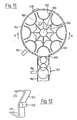
- Fig. 11 shows a drum-type magazine which can be substituted for the magazine of Fig. 8, the feed chute and the holder 110 remaining substantially the same.
- Drum-type magazines are not as such novel - see for example Japanese Published Patent Specification 47-25811. Such magazines present, however, a number of problems regarding control of bobbin movements into and out of the magazine, and the illustrated system shows elegant solutions to these problems.
- the outer shell 184 of the magazines is cylindrical and is fixed relative to the chute, having an opening 186 in alignment with the chute.
- a gate means 187 similar to the gate shown in Fig. 8 is located adjacent the junction between the chute and shell 184. Gate 187 is normally biased into the illustrated disposition in which it retains a first bobbin while a second bobbin rests on the first.
- a rotary member 188 Co-axial with shell 184 is a rotary member 188 carrying a plurality of bobbin receiving elements 190 at its periphery.
- Each element 190 is U-shaped in section, with the open side of the U facing radially outwardly towards the shell 184.
- the elements 190 are so located relative to shell 184 that a bobbin of predetermined size can be neatly received in the compartment defined between one element 190 and the shell.
- Member 188 is rotated about the axis of shell 184 by any suitable stepping drive means (not shown).
- the stepping drive means locates elements 190 successively in alignment with opening 186.
- a bobbin detector 192 e.g. a light barrier type of detector, is located in association with the compartment next to the opening 186 considered in the direction of rotation indicated by arrow A.
- a bobbin detector 194 is associated with the gate 187, and the gate is normally maintained full so that a "bobbin absent" signal from detector 194 indicates that the magazine is empty. The signal is passed to controller PC (Fig. 8) which causes the tender to move to a magazine loading position at one end of the machine.
- the controller PC (which receives signals indicating arrival at the machine end) causes the tender to move to the magazine loading position even if the magazine is still part full, i.e. even if a "bobbin present" signal is received from detector 194.
- the magazine is "topped up” each time the tender moves to the said machine end.
- controller PC will be receiving a "bobbin absent" signal from detector 192 and will cause the loading station to load a second bobbin into the compartment now associated with detector 192.
- Member 188 is then indexed through a further step in the direction of the arrow B, so that the second bobbin falls onto the first, that is the system is in the actually shown condition.
- the loading/stepping operation is then repeated, because detector 192 is still providing a "bobbin absent" signal.
- the number of repeats is dependent upon the capacity of the magazine, the process being repeated until detector 192 provides a "bobbin present" signal after stepping of the member 188.
- the second-loaded bobbin is so disposed in the chute, and the elements 190 are so disposed relative to the chute, that the third-loaded bobbin and subsequently loaded bobbins make line contact with the second-loaded bobbin during the stepping movements.
- the opening 186 is effectively “closed” (as far as the third and subsequently loaded bobbins are concerned) by the second-loaded bobbin.
- the tender arrives at the loading position with at least gate 187 and possibly some magazine compartments still occupied.
- the loading/stepping operation can be carried out exactly as for refilling of an empty magazine i.e. by reference to the output of detector 192; the number of bobbins loaded may be anywhere in the range 1 to (n+1), where n is the number of elements 190, depending on the level of fill before the start of loading.
- An indexing mechanism is preferably provided to ensure that at the end of each rotation step one of the compartments is accurately aligned with the opening 186.
- a suitable arrangement is illustrated in dotted lines in Fig. 11.
- member 188 is associated with a rotary plate 196 having a plurality of recesses corresponding respectively with the elements 190.
- a spring bias roller 198 secured (by means not shown) to the tender frame, engages successively in the recesses of plate 196 as the latter rotates with member 188 thus locating the member in successive positions determined by the co-operation of the roller and the recesses.
- a detector 200 responsive to a predetermined part of the member 188, e.g. the adjoining region between two successive elements 190, can be provided to indicate rotary alignment/misalignment of the member 188, and the controller PC can respond in accordance with a predetermined programme when a misalignment is indicated.
- the drum-type magazine could, of course, be used with cylindrical bobbins. However, the much simpler form of magazine illustrated in Fig. 8 is preferred wherever possible.
- the non-illustrated stepping mechanism could, for example, comprise a piston and cylinder unit adapted to pivot a pawl-like element co-operable with the indexing member 196. There may be two such piston and cylinder units, each with its respective pawl element for driving member 188 in the directions of arrows A and B respectively. Any alternative stepping mechanism could, of course, be used instead.
- the end faces of the drum may be closed except where an opening is left to enable loading of bobbins into a compartment aligned with the detector 192. This latter opening may be normally closable, but full closure of the end faces may in any event prove unnecessary since the bobbins are not normally subjected to any axial movement when located in their compartments.
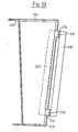
- Figs 12 and 13 show some further detail of a practical form of chute and gate mechanism designed specifically for conical bobbins, although modifications will readily be apparent to enable the use of the system with cylindrical bobbins.
- the chute is made up of two sheet metal portions 202, 204 respectively. These portions define a space 206 the cross section of which corresponds with the shape of the bobbins 208 to be controlled.
- the gate pivoting mechanism is provided in part by a circular section rod 210, which is rotatable (by means not shown) about its own longitudinal axis.
- a circular section rod 210 Secured to bar 210 at intervals spaced therealong are two cross pieces 212, 214 respectively (see Fig. 13).
- each cross piece carries a pair of arms 216, 218 respectively projecting from respective free ends of the cross piece.
- the arms 218 are joined by a bobbin engaging bar 220 (Fig. 13), and the arms 216 are joined by a similar bar (not seen in the figures).
- the arms on cross piece 212 are slightly longer than the arms on cross piece 214 in order to allow for the shape of the bobbin.
- Arms 218 normally project into the space 206 so that bar 220 underlies a bobbin 208 and prevents it moving down the feed chute under gravity. Arms 216 are normally withdrawn from the space 206.
- a conical bobbin 222 is shown in the winding position. Its axis BA is inclined at the angle ⁇ to the horizontal so that the bobbin makes line contact with the drive roll.
- the position in which bobbins are presented to the bobbin insertion device i.e. the collection position, is indicated in dotted lines at 224.
- the bobbin axis at the collection position is indicated at PA and is parallel to the axis BA.
- axis SA The axis of swing of the arm 32 of the bobbin insertion device is indicated at SA. Due to the adjustment of the sub-frame 180 as described with reference to Fig. 10, axis SA is parallel to axes BA and PA.
- a bobbin 208 is shown in the position in which it is held by the gate mechanism ready to fall to the position 224.
- the bobbin axis RA in this "ready" position is parallel to the axis PA, thus differing from the illustration in Fig. 11.
- the ready position shown in Fig. 14 is prefer necessarilyable to that shown in Fig. 11 because it requires no tilt of the incoming bobbin about its larger diameter end in passing from the gate to the position 224.
- a bobbin 226 is shown resting on the bobbin 208.
- the position of the axis of bobbin 226 is therefore determined by that of bobbin 208 and by the cone angle of the bobbins. The latter angle has been exaggerated in the drawings to facilitate illustration of the principle.
- the dotted lines 228 illustrate a bobbin held by one of the elements 90 in the drum magazine and "riding" on bobbin 226 during a loading operation as described above.
- the disposition of the axis of bobbin 228 is determined by that of bobbin 226 and the requirement that these two bobbins make line contact while bobbin 228 rides on bobbin 226.
- the disposition of the elements 90 must be designed accordingly.
- the hub member 188 of the drum magazine is shown. its axis 230 is arranged parallel to the line of contact between bobbins 226 and 228. It is thus inclined to the horizontal.
- the inclined disposition of the magazine facilitates loading of bobbins into the elements 190 by sliding of the bobbins in their axial direction under gravity or propulsion on a suitable oriented slide (not shown). Control of loading can therefore be effected by gates associated with the slide.
- the gripper 30 must also be adapted to conical bobbins by replacement of a yoke 68 (Fig. 4) with roller assemblies 74, 78 suited to cylindrical bobbins by a yoke with roller assemblies suited to the conicity of the bobbins to be gripped.
- the angle of offset of the shafts 98 of the roller assemblies relative to the axis of the shaft 60 is adapted to the bobbin conicity as well as to the skew required to produce the holding force F (Fig. 2).
- a complete package ejection/bobbin insertion sequence, and a complete set of equipment appropriate thereto, will vary substantially depending upon both the machine-type and the detailed design thereof. Purely by way of example, for the sake of completeness of the present specification, a complete set of equipment suitable for operating upon a specific design of open end spinning machine will be listed and very briefly described in the following.
- the open end spinning machine is of the type in which package winding is stopped when the package has reached a predetermined length, and the cradle mechanism is operated to lift the fully-wound package through a short distance away from the friction drive roll 10. In this "lifted-off position", the package awaits the arrival of the service tender.
- the tender After being located in registry with the spinning station, the tender first operates a "cradle lift” lever which engages the arm 16 of the cradle mechanism and lifts it to its uppermost position. As already described, the cradle will be maintained in this positon by the cradle mechanism of the machine. The tender then moves out a “doffing lever” which engages the underside of the package to support it. Further, the tender moves out an "upper cradle opener” which opens the cradle as described with reference to Fig. 2 in order to release the package, which is thereupon moved away from the cradle mechanism by the doff lever to a position at which the package is taken over by transport means on the machine.
- the doff lever is then withdrawin and the bobbin insertion arm is operated to bring a bobbin to the transfer location as described with reference to Figs. 1 and 3.
- the upper cradle opener is then operated to close the cradle; this opener also exerts a grip on the lever 16 and, after closing of the cradle, forces the cradle downwardly, initially against the action of the cradle mechanism.
- the upper cradle opener releases its grip on the cradle, and control of lowering of the cradle to the winding position is taken over by the cradle lift lever.
- the expressions "cradle” and “cradle mechanism” as used in both the description and claims are not limited to a package holding device comprising a pair of arms. Alternative systems are known.
- the bobbin is held upon a "chuck" member carried by a single arm swingable to produce the arc of movement 40 shown in Fig. 1.
- the chuck is mounted cantilever fashion on the arm, for example as shown in US Specification 3491961.
- the package/bobbin is held by clamping pressure applied to its ends; any convenient means may be used for this purpose.
- the terms "bobbin” and “bobbin tube” used herein are intended to be synonymous.
- the term “doffing” as used herein refers to an operating sequence including both package ejection and fresh bobbin insertion.
- the axis 182 about which the sub-frame 180 can be pivoted to adapt the tender is provided by a sub-frame mounting (not shown).
- the mounting is provided between sub-frame 180 and a cross piece 232 extending between and secured to the bulkheads 179.
- Cross piece 232 has a pair of curved slots 234 through which bolts can be extended to co-operate with portions of the sub-frame 180 in order to secure the sub-frame relative to the cross piece.
- a second cross piece 236 extends between bulkheads 179 adjacent the upper end of sub-frame 180 and is provided with a second pair of curved slots 238 for the same purpose as the slots 234.
- sub-frame 180 When the securing bolts are released, sub-frame 180 can be pivoted about axis 182 with bolts moving in a corresponding manner along their respective curved slots 234 or 238. When the sub-frame 180 is in the desired positon, the bolts can be re-tightened in order to hold the sub-frame relative to the cross pieces 232 and 236.
- the parts to be carried by the sub-frame 180 in a practical service tender will depend substantially upon the purpose for which said tender is designed, and in particular upon the machine with which the tender is to operate. By way of example only a complete set of equipment suitivelyable for performing a particular type of doffing operation was described above.
- Each of the elements referred to in that description i.e. the cradle lift lever, the doffing lever, the upper cradle opener, the bobbin inserting arm and the lower cradle opener
- the doff lever is preferably in the form of a "shovel" having a plate-like member adapted to engage the underside of a package to be doffed (i.e. the side facing the friction drive roller 10 shown in Fig. 1) along a substantial portion of the axial length of the package.
- This shovel member must maintain a substantially horizontal disposition despite tilting of the sub-frame 180 in order to adapt the tender for use with conical packages. This is because even a conical package remains in contact with a horizontally disposed friction drive roll as shown in and described with reference to Fig. 14.
- the doff lever may be mounted on sub-frame 180 for rotation thereon about its own longitudinal axis, so that the doff lever can be pivoted back to its required horizontal disposition despite tilting of the sub-frame.
- the doff lever could be mounted separately upon the frame of the tender so that it does not tilt with the sub-frame 180.
- sub-frame 180 will also carry certain elements shown in the co-pending application (610 B) of Manfred Schreiber and Andrè Lattion entitled OPEN END YARN PIECER and filed on even date namely the suction end finding nozzle 90, the yarn guide means 96, the yarn feed means 172 and the yarn manipulating means 174 shown in Fig. 4 of that Application. Again, however, since the end finding nozzle 90 is adapted to co-operate with the underside of the package (as clearly seen in Fig.
- the nozzle may be mounted on sub-frame 180 so as to permit pivoting of the end finding portion of the nozzle about the longitudinal nozzle axis relativ to the sub-frame 180.
- the portion of the nozzle which co-operates with the package in operation can be pivoted back to the required horizontal disposition despite pivoting of the main body of the nozzle (or of the pneumatic leads extending thereto) with the sub-frame 180.
Landscapes
- Replacing, Conveying, And Pick-Finding For Filamentary Materials (AREA)
- Spinning Or Twisting Of Yarns (AREA)
Priority Applications (2)
| Application Number | Priority Date | Filing Date | Title |
|---|---|---|---|
| EP89106775A EP0329202B1 (de) | 1983-05-20 | 1984-05-04 | Vorrichtung zum Einlegen von Spulenhülsen |
| AT89106775T ATE80860T1 (de) | 1983-05-20 | 1984-05-04 | Vorrichtung zum einlegen von spulenhuelsen. |
Applications Claiming Priority (5)
| Application Number | Priority Date | Filing Date | Title |
|---|---|---|---|
| GB08313994A GB2140046B (en) | 1983-05-20 | 1983-05-20 | Bobbin inserting device |
| GB8313994 | 1983-05-20 | ||
| GB838333471A GB8333471D0 (en) | 1983-12-15 | 1983-12-15 | Spinning machine tenders |
| GB8333471 | 1983-12-15 | ||
| EP89106775A EP0329202B1 (de) | 1983-05-20 | 1984-05-04 | Vorrichtung zum Einlegen von Spulenhülsen |
Related Parent Applications (1)
| Application Number | Title | Priority Date | Filing Date |
|---|---|---|---|
| EP84105036.2 Division | 1984-05-04 |
Publications (3)
| Publication Number | Publication Date |
|---|---|
| EP0329202A2 true EP0329202A2 (de) | 1989-08-23 |
| EP0329202A3 EP0329202A3 (en) | 1989-11-29 |
| EP0329202B1 EP0329202B1 (de) | 1992-09-23 |
Family
ID=27232360
Family Applications (1)
| Application Number | Title | Priority Date | Filing Date |
|---|---|---|---|
| EP89106775A Expired - Lifetime EP0329202B1 (de) | 1983-05-20 | 1984-05-04 | Vorrichtung zum Einlegen von Spulenhülsen |
Country Status (2)
| Country | Link |
|---|---|
| EP (1) | EP0329202B1 (de) |
| AT (1) | ATE80860T1 (de) |
Cited By (1)
| Publication number | Priority date | Publication date | Assignee | Title |
|---|---|---|---|---|
| CN112093583A (zh) * | 2020-09-24 | 2020-12-18 | 陕西华燕航空仪表有限公司 | 一种纺纱筒管定位装置 |
Citations (4)
| Publication number | Priority date | Publication date | Assignee | Title |
|---|---|---|---|---|
| CH555290A (de) * | 1973-03-05 | 1974-10-31 | Heberlein & Co Ag | Automatische spulenwechsel- und -transportvorrichtung. |
| FR2353661A1 (fr) * | 1976-06-01 | 1977-12-30 | Stahlecker Fritz | Metier a filer a fibres liberees (a bout ouvert) avec un dispositif d'echange de bobines pleines contre des tubes vides |
| GB2001362A (en) * | 1977-06-30 | 1979-01-31 | Ishikawa Seisakusho Kk | Doffing yarn packages: temporarily storing continuously delivered yarn |
| DE2947901A1 (de) * | 1979-11-28 | 1981-07-23 | W. Schlafhorst & Co, 4050 Mönchengladbach | Spulenwechselvorrichtung |
-
1984
- 1984-05-04 AT AT89106775T patent/ATE80860T1/de not_active IP Right Cessation
- 1984-05-04 EP EP89106775A patent/EP0329202B1/de not_active Expired - Lifetime
Patent Citations (4)
| Publication number | Priority date | Publication date | Assignee | Title |
|---|---|---|---|---|
| CH555290A (de) * | 1973-03-05 | 1974-10-31 | Heberlein & Co Ag | Automatische spulenwechsel- und -transportvorrichtung. |
| FR2353661A1 (fr) * | 1976-06-01 | 1977-12-30 | Stahlecker Fritz | Metier a filer a fibres liberees (a bout ouvert) avec un dispositif d'echange de bobines pleines contre des tubes vides |
| GB2001362A (en) * | 1977-06-30 | 1979-01-31 | Ishikawa Seisakusho Kk | Doffing yarn packages: temporarily storing continuously delivered yarn |
| DE2947901A1 (de) * | 1979-11-28 | 1981-07-23 | W. Schlafhorst & Co, 4050 Mönchengladbach | Spulenwechselvorrichtung |
Cited By (2)
| Publication number | Priority date | Publication date | Assignee | Title |
|---|---|---|---|---|
| CN112093583A (zh) * | 2020-09-24 | 2020-12-18 | 陕西华燕航空仪表有限公司 | 一种纺纱筒管定位装置 |
| CN112093583B (zh) * | 2020-09-24 | 2022-09-20 | 陕西华燕航空仪表有限公司 | 一种纺纱筒管定位装置 |
Also Published As
| Publication number | Publication date |
|---|---|
| EP0329202A3 (en) | 1989-11-29 |
| EP0329202B1 (de) | 1992-09-23 |
| ATE80860T1 (de) | 1992-10-15 |
Similar Documents
| Publication | Publication Date | Title |
|---|---|---|
| EP0205958B1 (de) | Einrichtung zum Führen eines Garnes | |
| US4555215A (en) | Spool transporting device | |
| US4598881A (en) | Bobbin inserting device | |
| US3295775A (en) | Method and apparatus for readying the winding operation of yarn supply coils on coil winding machines | |
| US4154411A (en) | Method and device for increasing the speed at which take-up coils are exchanged in a winding machine for textile threads | |
| US4899531A (en) | Method and apparatus for automatic exchange of roving bobbins of a ring spinning machine | |
| US4616789A (en) | Yarn end readying device in winder | |
| EP1028908B1 (de) | Wickler für synthetische filamente | |
| CN101513967A (zh) | 绕线机 | |
| EP0285186B1 (de) | Vorrichtung und Verfahren zum automatischen Spulenwechsel an einer Aufwickelmaschine | |
| US6015113A (en) | Winder for synthetic filaments | |
| GB2179066A (en) | Forming overwrapped thread reserves on bobbins | |
| US4638956A (en) | Textile machine for producing cross-wound bobbins | |
| EP0406923A2 (de) | Handhaben von Garnspulen mit einer gerichteten Form | |
| EP0329202A2 (de) | Vorrichtung zum Einlegen von Spulenhülsen | |
| EP0330245A2 (de) | Vorrichtung zum Einlegen von Spulenhülsen | |
| EP0198517A2 (de) | Spulenhülsen-Einlegevorrichtung | |
| US3389866A (en) | Method of operation of an automatic spool machine, in particular a crossspool automatic winding machine | |
| US4595151A (en) | Bobbin inserting device | |
| US4878342A (en) | Two-for-one twisting machine | |
| GB2179064A (en) | Bobbin doffing device | |
| GB2179376A (en) | Bobbin inserting device | |
| GB2179065A (en) | Bobbin donning | |
| US4702427A (en) | Coil producing machine | |
| CZ281430B6 (cs) | Způsob a zařízení k navíjení nitě na kuželovou cívku u dopřádacích strojů s otevřeným koncem |
Legal Events
| Date | Code | Title | Description |
|---|---|---|---|
| PUAI | Public reference made under article 153(3) epc to a published international application that has entered the european phase |
Free format text: ORIGINAL CODE: 0009012 |
|
| AC | Divisional application: reference to earlier application |
Ref document number: 126352 Country of ref document: EP |
|
| AK | Designated contracting states |
Kind code of ref document: A2 Designated state(s): AT BE CH DE FR IT LI NL |
|
| PUAL | Search report despatched |
Free format text: ORIGINAL CODE: 0009013 |
|
| AK | Designated contracting states |
Kind code of ref document: A3 Designated state(s): AT BE CH DE FR IT LI NL |
|
| 17P | Request for examination filed |
Effective date: 19900109 |
|
| 17Q | First examination report despatched |
Effective date: 19910613 |
|
| GRAA | (expected) grant |
Free format text: ORIGINAL CODE: 0009210 |
|
| AC | Divisional application: reference to earlier application |
Ref document number: 126352 Country of ref document: EP |
|
| AK | Designated contracting states |
Kind code of ref document: B1 Designated state(s): AT BE CH DE FR IT LI NL |
|
| PG25 | Lapsed in a contracting state [announced via postgrant information from national office to epo] |
Ref country code: NL Effective date: 19920923 Ref country code: BE Effective date: 19920923 Ref country code: AT Effective date: 19920923 |
|
| REF | Corresponds to: |
Ref document number: 80860 Country of ref document: AT Date of ref document: 19921015 Kind code of ref document: T |
|
| REF | Corresponds to: |
Ref document number: 3485940 Country of ref document: DE Date of ref document: 19921029 |
|
| ITF | It: translation for a ep patent filed |
Owner name: ING. ZINI MARANESI & C. |
|
| ET | Fr: translation filed | ||
| NLV1 | Nl: lapsed or annulled due to failure to fulfill the requirements of art. 29p and 29m of the patents act | ||
| PG25 | Lapsed in a contracting state [announced via postgrant information from national office to epo] |
Ref country code: LI Effective date: 19930531 Ref country code: CH Effective date: 19930531 |
|
| PLBE | No opposition filed within time limit |
Free format text: ORIGINAL CODE: 0009261 |
|
| STAA | Information on the status of an ep patent application or granted ep patent |
Free format text: STATUS: NO OPPOSITION FILED WITHIN TIME LIMIT |
|
| 26N | No opposition filed | ||
| PG25 | Lapsed in a contracting state [announced via postgrant information from national office to epo] |
Ref country code: FR Effective date: 19940131 |
|
| REG | Reference to a national code |
Ref country code: CH Ref legal event code: PL |
|
| REG | Reference to a national code |
Ref country code: FR Ref legal event code: ST |
|
| PGFP | Annual fee paid to national office [announced via postgrant information from national office to epo] |
Ref country code: DE Payment date: 20020511 Year of fee payment: 19 |
|
| PG25 | Lapsed in a contracting state [announced via postgrant information from national office to epo] |
Ref country code: DE Free format text: LAPSE BECAUSE OF NON-PAYMENT OF DUE FEES Effective date: 20031202 |