EP0328879A2 - Roller fork for rotary presses - Google Patents
Roller fork for rotary presses Download PDFInfo
- Publication number
- EP0328879A2 EP0328879A2 EP89100623A EP89100623A EP0328879A2 EP 0328879 A2 EP0328879 A2 EP 0328879A2 EP 89100623 A EP89100623 A EP 89100623A EP 89100623 A EP89100623 A EP 89100623A EP 0328879 A2 EP0328879 A2 EP 0328879A2
- Authority
- EP
- European Patent Office
- Prior art keywords
- roller
- pin
- bearing
- journal
- rotation
- Prior art date
- Legal status (The legal status is an assumption and is not a legal conclusion. Google has not performed a legal analysis and makes no representation as to the accuracy of the status listed.)
- Granted
Links
- 238000013016 damping Methods 0.000 abstract 1
- 230000007246 mechanism Effects 0.000 abstract 1
- XEEYBQQBJWHFJM-UHFFFAOYSA-N Iron Chemical compound [Fe] XEEYBQQBJWHFJM-UHFFFAOYSA-N 0.000 description 2
- 230000005540 biological transmission Effects 0.000 description 1
- 238000006073 displacement reaction Methods 0.000 description 1
- 238000005516 engineering process Methods 0.000 description 1
- 229910052742 iron Inorganic materials 0.000 description 1
- 238000005096 rolling process Methods 0.000 description 1
Images
Classifications
-
- B—PERFORMING OPERATIONS; TRANSPORTING
- B41—PRINTING; LINING MACHINES; TYPEWRITERS; STAMPS
- B41F—PRINTING MACHINES OR PRESSES
- B41F31/00—Inking arrangements or devices
- B41F31/30—Arrangements for tripping, lifting, adjusting, or removing inking rollers; Supports, bearings, or forks therefor
- B41F31/304—Arrangements for inking roller bearings, forks or supports
- B41F31/305—Eccentric bearings
Definitions
- the invention relates to a roller bearing for rollers of ink and dampening units on rotary printing presses according to the preamble of the claim.
- a roller bearing of the type mentioned is known from DE-Gbm 1 995 046.
- the roller receiving piece is designed as a stepped pin in the form of a plug-in bearing, a pin on the pin being axially displaceably mounted in the eccentric bushing.
- These bearings have disadvantages in terms of operation because they require two-man operation or additional devices for holding the roller when it is inserted axially into the bearing point.
- the object of the invention is therefore to enable a sensitive setting in a device of the type mentioned, in which a considerable reduction in the angle of rotation of the adjusting movement of the eccentric bushing relative to the rotation of the roller receiving piece is ensured.
- the roller bearing according to the invention has advantages in terms of operation and, at the same time, enables the assembly or disassembly direction to be approximately maintained when the roller is adjusted.
- the pin 13 of a transfer roller 1 carries a roller bearing 12 which is encased with a bearing ring 4.
- the bearing ring 4 has, on opposite sides, a flattened, double-edged guide pin 14 which, together with the bearing ring 4 receiving the roller 1, is placed in a bearing body 20 of a roller receiving piece 3 which is open on one side and which has a slot S corresponding to the width of the flattened guide pin 14.
- the roll holder 3 is provided with a pin 15 which is rotatably arranged in an eccentric bush 5 in the bearing block 6 on the side stands 19 of the printing press.
- the pin 13 of the roller 1, the guide pin 14 of the bearing ring 4 and the pin 15 of the roller receiving piece 3 are aligned with one another with an axis 16, i. H. arranged coaxially.
- the roller bearings 12, the bearing ring 4 and the bearing body 20 which is open on one side are also coaxial.
- the guide pin 14 of the bearing ring 4 After inserting the guide pin 14 of the bearing ring 4, it is turned to the right or left. As a result, the curved part of the guide pin 14 shifts into the bearing bore of the bearing body 3 that is open on one side until a resilient pressure piece 11 of the guide pin 14 engages in a recess on the bearing body 20 that is open on one side. Thus, the guide pin 14 is closed in the bearing body 20, which is open on one side, and secured against rotation.
- the pin 15 of the roller holder 3 can optionally also be mounted directly in the side stand 19, or in a hinged to the side stand, not shown in the drawing, if the roller 1 is also to be pivoted on and off.
- the receiving bore for the eccentric bushing 5 in the bearing block 6 is narrowly slotted so that the eccentric bushing 5 can be clamped there by means of a clamping screw 7 and at the same time secured against axial displacement.
- Clamping screw 7 can be canceled.
- the eccentric bush 5 can then be rotated by means of a dowel pin via the holes 17 assigned to the circumference.
- the pin 15 of the roll receiving piece 3 is provided on the end face in the assembly or disassembly direction with a groove 18, equal to the position of the slot S.
- One end of an anti-rotation lever 8 engages in the groove 18, in the manner of a sliding joint.
- the anti-rotation lever 8 has z. B. the shape of a flat iron with a corresponding guide in the groove 18. With its other end, this lever 8 is pivotally mounted about a pivot point parallel to the pin 15 by means of the pivot joint 10 in the bearing block 6.
- the slot S of the open-ended bearing body 20 rotates and thus also the assembly and disassembly direction of the roller 1 only slightly by half the angle ⁇ .
- the assembly or disassembly direction is rotated by the angle ⁇ , when the eccentric bushing 5 is rotated by 180 degrees, e.g. left to right in a lateral direction.
- the device according to the invention thus allows a sensitive adjustment of the roller 1 with respect to the roller 2, with a minimal change in the assembly or disassembly direction of the roller 1.
- the roller 1 is also securely, precisely and free of wear.
- the anti-rotation device according to the invention with the components 3, 5, 6, 8, 10, 18 could be understood as a vibrating crank loop with a modified thrust joint shape 18 in relation to the movement sequence, in which the eccentric bush 5 represents a special form of a crank which is in the side stand 19 is clampable.
Landscapes
- Rolls And Other Rotary Bodies (AREA)
- Inking, Control Or Cleaning Of Printing Machines (AREA)
- Support Of The Bearing (AREA)
- Forklifts And Lifting Vehicles (AREA)
- Motor Or Generator Frames (AREA)
- Rolling Contact Bearings (AREA)
- Rotary Presses (AREA)
Abstract
Description
Die Erfindung betrifft ein Walzenlager für Walzen von Farb- und Feuchtwerken an Rotationsdruckmaschinen nach dem Oberbegriff des Patentanspruches.The invention relates to a roller bearing for rollers of ink and dampening units on rotary printing presses according to the preamble of the claim.
Ein Walzenlager genannter Gattung ist aus dem DE-Gbm 1 995 046 bekannt. Das Walzenaufnahmestück ist als abgesetzter Bolzen ausgeführt in Form eines Stecklagers, wobei ein Zapfen am Bolzen axial verschiebbar in der Exzenterbüchse gelagert ist. Diese Lager haben Nachteile bei der Bedienung, weil sie eine Zwei-Mann-Bedienung oder zusätzliche Vorrichtungen zum Halten der Walze beim axialen Einführen in die Lagerstelle erfordern.A roller bearing of the type mentioned is known from DE-Gbm 1 995 046. The roller receiving piece is designed as a stepped pin in the form of a plug-in bearing, a pin on the pin being axially displaceably mounted in the eccentric bushing. These bearings have disadvantages in terms of operation because they require two-man operation or additional devices for holding the roller when it is inserted axially into the bearing point.
Bei einer weiteren bekannten Ausführung sind z. B. zwei Auftragwalzen schwenkbar um eine Reibwalze in Schwenkhebeln angeordnet. Die Einstellung des Achsabstandes zwischen Auftragswalzen und Reibwalze erfolgt ebenfalls über Exzenter, die auf der Reibwalzenwelle angeordnet sind (siehe DE-PS 1 242 636).In a further known embodiment, for. B. two applicator rollers pivotally arranged about a friction roller in pivot levers. The adjustment of the center distance between application rollers and distribution roller is also carried out via eccentrics which are arranged on the distribution roller shaft (see DE-PS 1 242 636).
Aus der DE-AS 1 268 443 ist es auch bereits bekannt, einen einseitig offenen Lagerkörper mit seinem Zapfen gestellfest exzentrisch zu lagern. Da aber der einseitig offene Lagerkörper mit dem exzentrisch angeordneten Zapfen aus einem Stück besteht, verdreht sich, falls durch eine einfache Exzenterverdrehung die gelagerte Walze gegen eine andere Walze eingestellt werden soll, auch die Montage- bzw. Demontagerichtung mit gleichem Drehwinkel, je nach Verdrehung. Dies ist aber dann nicht zu vertreten, wenn Walzen nur von einer Seite mit möglichst gleichbleibender Montage- bzw. Demontagerichtung zugänglich sein sollen, weil alle anderen Seiten durch anliegende Farb- oder Feuchtwerkswalzen oder durch Maschinenteile verdeckt sind.From DE-AS 1 268 443 it is also known to mount a bearing body which is open on one side and eccentrically with its pin fixed to the frame. However, since the bearing body, which is open on one side, with the eccentrically arranged pin consists of one piece, if the roller is to be set against another roller by simply turning the eccentric, the direction of assembly or disassembly also rotates with the same angle of rotation, depending on the rotation. However, this is not to be justified if rollers should only be accessible from one side with the assembly or disassembly direction being as constant as possible, because all other sides are covered by adjacent inking or dampening unit rollers or by machine parts.
Aufgabe der Erfindung ist es deshalb, bei einer Vorrichtung der genannten Gattung eine feinfühlige Einstellung zu ermöglichen, bei der eine erhebliche Drehwinkeluntersetzung der Stellbewegung der Exzenterbuchse gegenüber der Verdrehung des Walzenaufnahmestückes gewährleistet ist.The object of the invention is therefore to enable a sensitive setting in a device of the type mentioned, in which a considerable reduction in the angle of rotation of the adjusting movement of the eccentric bushing relative to the rotation of the roller receiving piece is ensured.
Gelöst wird diese Aufgabe gemäß dem Kennzeichen des Patentanspruches.This object is achieved according to the characterizing part of the patent claim.
Das erfindungsgemäße Walzenlager hat Vorteile bei der Bedienung und ermöglicht es zugleich, daß bei der Einstellung der Walze die Montage- bzw. Demontagerichtung annähernd erhalten bleibt.The roller bearing according to the invention has advantages in terms of operation and, at the same time, enables the assembly or disassembly direction to be approximately maintained when the roller is adjusted.
Die Erfindung soll anhand der Zeichnung an einem Ausführungsbeispiel nachstehen näher erläutert werden.The invention will be explained in more detail with reference to the drawing of an embodiment.
Es zeigt:
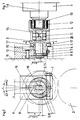
Figur 1 das Walzenlager in geöffnetem Zustand, wobei der abgeflachte Zapfen eines die Walze aufnehmenden Lagerringes in einen einseitig offenen Lagerkörper eingelegt ist,Figur 2 eine Ansicht nach Schnitt A - A derFigur 1.
- 1 shows the roller bearing in the open state, the flattened pin of a bearing ring receiving the roller being inserted into a bearing body which is open on one side,
- FIG. 2 shows a view according to section AA of FIG. 1.
Der Zapfen 13 einer Übertragungswalze 1 trägt ein Wälzlager 12, das mit einem Lagerring 4 umhüllt ist. Der Lagerring 4 besitzt an gegenüberliegenden Seiten einen abgeflachten, zweikantigen Führungszapfen 14, der gemeinsam mit dem die Walze 1 aufnehmenden Lagerring 4 in einen einseitig offenen Lagerkörper 20 eines Walzenaufnahmestückes 3 eingelegt ist, welches entsprechend der Breite des abgeflachten Führungszapfens 14 einen Schlitz S aufweist.The
Das Walzenaufnahmestück 3 ist mit einem Zapfen 15 versehen, der drehbar in einer Exzenterbuchse 5 im Lagerbock 6 an den Seitenständern 19 der Druckmaschine angeordnet ist.The
Der Zapfen 13 der Walze 1, der Führungszapfen 14 des Lagerringes 4 und der Zapfen 15 des Walzenaufnahmestückes 3 sind fluchtend zueinander mit einer Achse 16, d. h. koaxial angeordnet. Ebenso koaxial sind die Wälzlager 12, der Lagerring 4 und der einseitig offene Lagerkörper 20 angeorndet.The
Nach dem Einlegen des Führungszapfens 14 des Lagerringes 4 wird dieser rechts oder links gedreht. Dadurch verschiebt sich der gekrümmte Teil des Führungszapfens 14 in die Lagerbohrung des einseitig offenen Lagerkörpers 3, bis ein federndes Druckstück 11 des Führungszapfens 14 in eine Ausnehmung an einseitig offenen Lagerkörper 20 einrastet. Somit ist der Führungszapfen 14 im einseitig offenen Lagerkörper 20 verschlossen und gegen Verdrehen gesichert.After inserting the
Der Zapfen 15 des Walzenaufnahmestückes 3 kann gegebenenfalls auch direkt im Seitenständer 19, oder auch in einem am Seitenständer angelenkten, in der Zeichnung nicht näher dargestellten An- und Abstellhebel gelagert sein, wenn die Walze 1 zusätzlich an- und abschwenkbar sein soll.The
Die Aufnahmebohrung für die Exzenterbuchse 5 im Lagerbock 6 ist schmal geschlitzt, so daß mittels einer Spannschraube 7 die Exzenterbuchse 5 dort geklemmt und zugleich gegen axiales Verschieben gesichert werden kann.The receiving bore for the
Durch einen Gewindestift 9, dessen Zapfen in einer Ringnut des Zapfens 15 des Walzenaufnahmestückes 3 eingreift, wird dieses axial gesichert.This is axially secured by a
Soll die Walze 1 gegen eine Walze 2 eingestellt werden, muß zunächst die Klemmung der Exzenterbuchse 5 im Lagerbock 6 durch Betätigen derIf the
Spannschraube 7 aufgehoben werden. Mittels Spannstift läßt sich dann über die am Umfang zugeordneten Bohrungen 17 die Exzenterbuchse 5 verdrehen.Clamping
Der Zapfen 15 des Walzenaufnahmestückes 3 ist stirnseitig in Montage- bzw. Demontagerichtung mit einer Nut 18 versehen, gleich der Lage des Schlitzes S. In die Nut 18 greift das eine Ende eines Verdrehsicherungshebels 8 ein, nach Art eines Schubgelenkes. Der Verdrehsicherungshebel 8 besitzt z. B. die Form eines Flacheisens mit entsprechender Führung in der Nut 18. Mit seinem anderen Ende ist dieser Hebel 8 um einen Drehpunkt parallel zum Zapfen 15 mittels des Drehgelenks 10 im Lagerbock 6 gestellfest schwenkbar gelagert.The
Beim Verdrehen der Exzenterbuchse 5 z. B. um 90 Grad nach links oder rechts (siehe Figur 2), verdreht sich der Schlitz S des einseitig offenen Lagerkörpers 20 und somit auch die Montage- bzw. Demontagerichtung der Walze 1 nur geringfügig um die Hälfte des Winkelsα. Die Größe dieser Verdrehung wird durch das Verhältnis der Exzentrizität a zum Abstand b, welcher zwischen Drehgelenk 10 und der Mittelachse der Lagerbohrung der Exzenterbuchse 5 gebildet wird, mit a:b =α:2 vorgegeben. Im ungünstigsten Fall erfolgt die Verdrehung der Montage- bzw. Demontagerichtung um den Winkelα, bei Verdrehung der Exzenterbuchse 5 um 180 Grad von z.B. links nach rechts in seitlicher Richtung.When turning the eccentric bush 5 z. B. by 90 degrees to the left or right (see Figure 2), the slot S of the open-ended bearing
Die erfindungsgemäße Vorrichtung erlaubt somit eine feinfühlige Einstellung der Walze 1 gegenüber der Walze 2, bei minimaler Veränderung der Montage- bzw. Demontagerichtung der Walze 1.The device according to the invention thus allows a sensitive adjustment of the
Bei ordnungsgemäß verriegeltem Lagerring 4 im einseitig offenen Lagerkörper 20 auch die Walze 1 sicher, genau und verschleißfrei aufgenommen.When the
Getriebetechnisch könnte die erfindungsgemäße Verdrehsicherung mit den Bauteilen 3, 5, 6, 8, 10, 18 in Bezug auf den Bewegungsablauf als eine schwingende Kurbelschleife mit geänderter Schubgelenkform 18 aufgefaßt werden, bei der die Exzenterbuchse 5 eine Sonderform einer Kurbel darstellt, die im Seitenständer 19 klemmbar ist.In terms of transmission technology, the anti-rotation device according to the invention with the
- 1 einstellbare Walze1 adjustable roller
- 2 feststehende Walze2 fixed roller
- 3 Walzenaufnahmestück3 roll holder
- 4 Lagerring4 bearing ring
- 5 Exzenterbuchse5 eccentric bushing
- 6 Lagerbock6 bearing block
- 7 Spannschraube7 clamping screw
- 8 Verdrehsicherungshebel8 anti-rotation lever
- 9 Gewindestift9 grub screw
- 10 Drehgelenk10 swivel
- 11 federndes Druckstück11 resilient pressure piece
- 12 Wälzlager12 rolling bearings
- 13 Zapfen13 cones
- 14 Führungszapfen14 guide pins
- 15 Zapfen15 cones
- 16 Achse16 axis
- 17 Bohrung17 hole
- 18 Nut18 groove
- 19 Seitenständer19 side stands
- 20 einseitig offener Lagerkörper20 bearing bodies open on one side
Claims (2)
dadurch gekennzeichnet,
daß der Zapfen (15) des Walzenaufnahmestückes (3) verdrehbar in der Exzenterbuchse (5) gelagert ist, wobei als Verdrehsicherung an dem Zapfen (15) eine Nut (18) vorgesehen ist, in der mit einem Ende ein Verdrehsicherungshebel (8) schubgelenkartig geführt ist, der mit seinem anderen Ende um ein zum Zapfen (15) paralleles Drehgelenk (10) gestellfest schwenkbar gelagert ist, daß die Wälzlager (12) auf dem Zapfen (13) der Walze (1) angeordnet mit ihrem Außenring in einem allseitig geschlossenen Lagerring (4) aufgenommen sind, der einen zweikantig abgeflachten Führungszapfen (14) aufweist und daß das Walzenaufnahmestück (3) einen einseitig offenen Lagerkörper (20) mit einem Schlitz (S) gleichgerichtet mit der Nut (18) des Zapfens (15) aufweist, durch den der zweikantig abgeflachte Führungszapfen (14) einlegbar und durch Verdrehen im einseitig offenen Lagerkörper (20) verschlossen ist.1.) Roller bearings for rotary printing presses with an eccentric bushing, which can be rotated in its seat in the frame for the purpose of one-time adjustment and can be clamped in this position by means of a clamping screw, and also with a roller receiving piece that is coaxially supported with a pin in the eccentric bushing a ball bearing in which the roller axis is rotatably received and finally with an anti-rotation device with which the pin of the roller receptacle can be locked in its position of use,
characterized,
that the pin (15) of the roller receiving piece (3) is rotatably mounted in the eccentric bushing (5), a groove (18) being provided on the pin (15) as a means of preventing rotation, in which one end an anti-rotation lever (8) is guided in the manner of a sliding joint is, which is pivotally mounted with its other end about a pivot joint (10) parallel to the pivot (15) so that the roller bearings (12) are arranged on the pivot (13) of the roller (1) with their outer ring in a bearing ring which is closed on all sides (4) are received, which has a two-sided flattened guide pin (14) and that the roller receiving piece (3) has a bearing body (20) open on one side with a slot (S) aligned with the groove (18) of the pin (15) which the two-sided flattened guide pin (14) can be inserted and closed by twisting in the open-ended bearing body (20).
dadurch gekennzeichnet,
daß im Führungszapfen (14) des Lagerringes (4) ein federndes Druckstück (11) angeordnet ist, das in eine Ausnehmung des einseitig offenen Lagerkörpers (20) beim Verschließen einrastet.2.) roller bearings for roationa printing machines according to claim 1,
characterized,
that in the guide pin (14) of the bearing ring (4) a resilient pressure piece (11) is arranged, which engages in a recess of the open-sided bearing body (20) when closing.
Priority Applications (1)
| Application Number | Priority Date | Filing Date | Title |
|---|---|---|---|
| AT89100623T ATE78434T1 (en) | 1988-02-19 | 1989-01-14 | ROLLER BEARING FOR ROTARY PRINTING MACHINES. |
Applications Claiming Priority (2)
| Application Number | Priority Date | Filing Date | Title |
|---|---|---|---|
| DE3805143A DE3805143C1 (en) | 1988-02-19 | 1988-02-19 | |
| DE3805143 | 1988-02-19 |
Publications (3)
| Publication Number | Publication Date |
|---|---|
| EP0328879A2 true EP0328879A2 (en) | 1989-08-23 |
| EP0328879A3 EP0328879A3 (en) | 1990-07-04 |
| EP0328879B1 EP0328879B1 (en) | 1992-07-22 |
Family
ID=6347697
Family Applications (1)
| Application Number | Title | Priority Date | Filing Date |
|---|---|---|---|
| EP89100623A Expired - Lifetime EP0328879B1 (en) | 1988-02-19 | 1989-01-14 | Roller fork for rotary presses |
Country Status (7)
| Country | Link |
|---|---|
| US (1) | US4953462A (en) |
| EP (1) | EP0328879B1 (en) |
| JP (1) | JPH01249349A (en) |
| AT (1) | ATE78434T1 (en) |
| BR (1) | BR8900258A (en) |
| DE (2) | DE3805143C1 (en) |
| ES (1) | ES2034406T3 (en) |
Cited By (3)
| Publication number | Priority date | Publication date | Assignee | Title |
|---|---|---|---|---|
| WO1991016201A1 (en) * | 1990-04-24 | 1991-10-31 | Gustav Rennerfelt | Bearing device for side register |
| DE4012928A1 (en) * | 1990-04-24 | 1991-10-31 | Roland Man Druckmasch | BOW TRANSPORT DRUM FOR SLOPE REGISTER CORRECTION |
| US5403099A (en) * | 1992-12-23 | 1995-04-04 | Heidelberger Druckmaschinen Ag | Roller bearing for rollers in printing units of a printing machine |
Families Citing this family (19)
| Publication number | Priority date | Publication date | Assignee | Title |
|---|---|---|---|---|
| DE3934070A1 (en) * | 1989-10-12 | 1991-04-25 | Miller Johannisberg Druckmasch | CHANGING APPLICATION ROLLER OF A INK PRINTING MACHINE |
| US5092240A (en) * | 1990-02-28 | 1992-03-03 | Wpc Machinery Corporation | Easily removable mounting and drive assembly for a rotating cylinder of a printing unit |
| DE4415340C2 (en) * | 1994-05-02 | 1996-03-14 | Roland Man Druckmasch | Printing unit cylinder of a web-fed rotary printing press |
| US5458061A (en) * | 1994-05-13 | 1995-10-17 | Mitsubishi Jukogyo Kabushiki Kaisha | Printing press |
| US5630364A (en) * | 1994-05-13 | 1997-05-20 | Mitsubishi Jukogyo Kabushiki Kaisha | Printing press |
| US5873141A (en) * | 1996-07-23 | 1999-02-23 | Tackett; Shelby G. | Windshield and wiper preservation device |
| US5943955A (en) | 1997-08-29 | 1999-08-31 | Goss Graphic Systems, Inc. | Printing press having cantilevered self-driven cylinders |
| DE19803558A1 (en) * | 1998-01-30 | 1999-08-12 | Koenig & Bauer Ag | Method for determining an angular position of a displaceable cylinder of a printing press |
| DE10006124A1 (en) * | 2000-02-11 | 2001-08-16 | Hauni Maschinenbau Ag | Printing unit for printing an envelope strip for smoking articles |
| DE10111068B4 (en) * | 2000-04-07 | 2018-01-18 | Heidelberger Druckmaschinen Ag | Roller lock for releasably securing a roller in a printing machine |
| DE10215613A1 (en) * | 2002-04-09 | 2003-10-30 | Roland Man Druckmasch | Roller lock for rollers of printer's inker and humidifier has bearing shell holding roller stud, clamp, and tensioning element |
| JP4025214B2 (en) * | 2003-02-20 | 2007-12-19 | 株式会社小森コーポレーション | Forming roller device for printing press |
| US7032515B2 (en) * | 2003-03-06 | 2006-04-25 | Goss International Corporation | Method and apparatus for changing print length on a printing press |
| DE112005003455B4 (en) * | 2005-05-03 | 2017-11-30 | Blickle Sondermaschinen Gmbh & Co. Kg | Device for rotary processing of rolls |
| JP5997428B2 (en) * | 2011-10-26 | 2016-09-28 | オイレス工業株式会社 | Air roll unit |
| CN102909940B (en) * | 2012-10-19 | 2014-06-18 | 浙江美格机械股份有限公司 | Multi-rubber-roll interchanging device for photogravure press |
| US20180031446A1 (en) * | 2016-07-29 | 2018-02-01 | Minebea Co., Ltd. | Bearing arrangement |
| WO2021028932A1 (en) * | 2019-08-10 | 2021-02-18 | Niki Narendrabhai Thakore | Rotary printing machine with combination of open and close bearing assembly |
| CN110948864A (en) * | 2019-12-20 | 2020-04-03 | 盐城威布三维科技有限公司 | 3D printer of convertible nozzle |
Citations (4)
| Publication number | Priority date | Publication date | Assignee | Title |
|---|---|---|---|---|
| FR565511A (en) * | 1923-04-25 | 1924-01-29 | Device for adjusting the rollers of printing machines | |
| DE937526C (en) * | 1952-01-25 | 1956-01-12 | Koenig & Bauer Schnellpressfab | Inking roller bearings for printing machines |
| GB1278245A (en) * | 1968-10-16 | 1972-06-21 | Ernest Arthur Timson | Improvements relating to printing machines |
| US4407198A (en) * | 1982-04-15 | 1983-10-04 | M.A.N.-Roland Druckmaschinen Aktiengesellschaft | Arrangement for securing pure skew adjustment of a plate cylinder in a sheet-fed rotary printing press |
Family Cites Families (6)
| Publication number | Priority date | Publication date | Assignee | Title |
|---|---|---|---|---|
| DE1995046U (en) * | 1968-10-24 | Koenig & Bauer Ag | Roller bearings for varnish and fire rollers of printing units; A.nm: Schnellpressenfabrik '^ oenig?; Bauer A.G., T700 ', Juerzburg | |
| US1816948A (en) * | 1929-05-04 | 1931-08-04 | Wood Newspaper Mach Corp | Lock-up for rolls |
| DE1268443B (en) * | 1963-03-04 | 1968-05-16 | Leipzig Veb Druckmasch Werke | Roller bearings for printing machines or the like, in which the axle stubs of the rollers are inserted into the bearing points |
| DE1242636B (en) * | 1964-05-19 | 1967-06-22 | Planeta Veb Druckmasch Werke | Device for adjusting the applicator rollers of inking and dampening units of rotary printing machines, in particular offset printing machines |
| DE3004921C2 (en) * | 1980-02-09 | 1982-07-22 | M.A.N.- Roland Druckmaschinen AG, 6050 Offenbach | Device for the lateral fastening of a printing machine roller |
| DD238358A1 (en) * | 1985-06-17 | 1986-08-20 | Polygraph Leipzig | ROLLING STOCK |
-
1988
- 1988-02-19 DE DE3805143A patent/DE3805143C1/de not_active Expired
-
1989
- 1989-01-14 AT AT89100623T patent/ATE78434T1/en not_active IP Right Cessation
- 1989-01-14 ES ES198989100623T patent/ES2034406T3/en not_active Expired - Lifetime
- 1989-01-14 DE DE8989100623T patent/DE58901858D1/en not_active Expired - Lifetime
- 1989-01-14 EP EP89100623A patent/EP0328879B1/en not_active Expired - Lifetime
- 1989-01-23 BR BR898900258A patent/BR8900258A/en not_active IP Right Cessation
- 1989-02-16 US US07/311,724 patent/US4953462A/en not_active Expired - Fee Related
- 1989-02-17 JP JP1036437A patent/JPH01249349A/en active Pending
Patent Citations (4)
| Publication number | Priority date | Publication date | Assignee | Title |
|---|---|---|---|---|
| FR565511A (en) * | 1923-04-25 | 1924-01-29 | Device for adjusting the rollers of printing machines | |
| DE937526C (en) * | 1952-01-25 | 1956-01-12 | Koenig & Bauer Schnellpressfab | Inking roller bearings for printing machines |
| GB1278245A (en) * | 1968-10-16 | 1972-06-21 | Ernest Arthur Timson | Improvements relating to printing machines |
| US4407198A (en) * | 1982-04-15 | 1983-10-04 | M.A.N.-Roland Druckmaschinen Aktiengesellschaft | Arrangement for securing pure skew adjustment of a plate cylinder in a sheet-fed rotary printing press |
Cited By (3)
| Publication number | Priority date | Publication date | Assignee | Title |
|---|---|---|---|---|
| WO1991016201A1 (en) * | 1990-04-24 | 1991-10-31 | Gustav Rennerfelt | Bearing device for side register |
| DE4012928A1 (en) * | 1990-04-24 | 1991-10-31 | Roland Man Druckmasch | BOW TRANSPORT DRUM FOR SLOPE REGISTER CORRECTION |
| US5403099A (en) * | 1992-12-23 | 1995-04-04 | Heidelberger Druckmaschinen Ag | Roller bearing for rollers in printing units of a printing machine |
Also Published As
| Publication number | Publication date |
|---|---|
| EP0328879A3 (en) | 1990-07-04 |
| JPH01249349A (en) | 1989-10-04 |
| BR8900258A (en) | 1989-09-19 |
| ATE78434T1 (en) | 1992-08-15 |
| DE3805143C1 (en) | 1989-03-23 |
| DE58901858D1 (en) | 1992-08-27 |
| ES2034406T3 (en) | 1993-04-01 |
| EP0328879B1 (en) | 1992-07-22 |
| US4953462A (en) | 1990-09-04 |
Similar Documents
| Publication | Publication Date | Title |
|---|---|---|
| EP0328879B1 (en) | Roller fork for rotary presses | |
| DE19511710C1 (en) | Bearing for journal of cylinder in printing machine | |
| DE3942189C1 (en) | ||
| DE3119879C2 (en) | Device for setting and lifting an application roller of a rotary printing press with tiltable cylinders | |
| DE69119438T2 (en) | Color device for printing machines | |
| EP0401500A2 (en) | Device for positioning a flexible printing plate on the plate cylinder of a notary printing machine | |
| DE2627963C2 (en) | Device on printing machines for adjusting the inking rollers that can be brought into contact with the plate cylinder | |
| DE10102734B4 (en) | Apparatus for driving a rubbing roller in a printing machine | |
| EP0387486B1 (en) | Driving mechanism for the axial movement of the first or both first and second rollers of a couple of rearrangeable roller in offset printing presses | |
| DE10111068B4 (en) | Roller lock for releasably securing a roller in a printing machine | |
| DE4400563C2 (en) | Roller in an inking unit or dampening unit of a rotary printing press | |
| DE4013416C1 (en) | ||
| DE2029007C3 (en) | Device for adjusting the printing force of an applicator roller of a dampening unit of an offset printing machine, which is mounted in holders | |
| EP1707361B1 (en) | Applicator roller for an offset printing group | |
| EP1361055B1 (en) | Drive for an oscillating roller | |
| DE9113505U1 (en) | Device for adjusting the circumferential register on rotary printing machines | |
| DE4142754C2 (en) | Device for adjusting the printing pressure of cylinders in printing machines | |
| DE69802637T2 (en) | Adjustment mechanism for inking rollers in a printing press | |
| DE4302149A1 (en) | Plate-cylinder alignment guide in rotary printing press | |
| DE60222987T2 (en) | jaw cylinder | |
| DD149187A5 (en) | DEVICE FOR DOSING A LIQUID ON A SPIDER SHAPED BY TWO ROLLERS | |
| DE19528623A1 (en) | Axial bearing for a shaft of an OE spinning rotor | |
| DE912816C (en) | Device for adjusting and checking the inking and application rollers on printing machines | |
| DE9316916U1 (en) | Combined wet inking unit | |
| DE2124234C3 (en) | Device for adjusting the spring force on folding rollers |
Legal Events
| Date | Code | Title | Description |
|---|---|---|---|
| PUAI | Public reference made under article 153(3) epc to a published international application that has entered the european phase |
Free format text: ORIGINAL CODE: 0009012 |
|
| AK | Designated contracting states |
Kind code of ref document: A2 Designated state(s): AT BE CH DE ES FR GB IT LI NL SE |
|
| PUAL | Search report despatched |
Free format text: ORIGINAL CODE: 0009013 |
|
| AK | Designated contracting states |
Kind code of ref document: A3 Designated state(s): AT BE CH DE ES FR GB IT LI NL SE |
|
| 17P | Request for examination filed |
Effective date: 19900607 |
|
| 17Q | First examination report despatched |
Effective date: 19911217 |
|
| ITF | It: translation for a ep patent filed | ||
| GRAA | (expected) grant |
Free format text: ORIGINAL CODE: 0009210 |
|
| AK | Designated contracting states |
Kind code of ref document: B1 Designated state(s): AT BE CH DE ES FR GB IT LI NL SE |
|
| REF | Corresponds to: |
Ref document number: 78434 Country of ref document: AT Date of ref document: 19920815 Kind code of ref document: T |
|
| ET | Fr: translation filed | ||
| REF | Corresponds to: |
Ref document number: 58901858 Country of ref document: DE Date of ref document: 19920827 |
|
| GBT | Gb: translation of ep patent filed (gb section 77(6)(a)/1977) | ||
| REG | Reference to a national code |
Ref country code: ES Ref legal event code: FG2A Ref document number: 2034406 Country of ref document: ES Kind code of ref document: T3 |
|
| PLBE | No opposition filed within time limit |
Free format text: ORIGINAL CODE: 0009261 |
|
| STAA | Information on the status of an ep patent application or granted ep patent |
Free format text: STATUS: NO OPPOSITION FILED WITHIN TIME LIMIT |
|
| 26N | No opposition filed | ||
| EAL | Se: european patent in force in sweden |
Ref document number: 89100623.1 |
|
| PGFP | Annual fee paid to national office [announced via postgrant information from national office to epo] |
Ref country code: BE Payment date: 19951215 Year of fee payment: 8 |
|
| PGFP | Annual fee paid to national office [announced via postgrant information from national office to epo] |
Ref country code: FR Payment date: 19951219 Year of fee payment: 8 |
|
| PGFP | Annual fee paid to national office [announced via postgrant information from national office to epo] |
Ref country code: SE Payment date: 19951221 Year of fee payment: 8 Ref country code: NL Payment date: 19951221 Year of fee payment: 8 |
|
| PGFP | Annual fee paid to national office [announced via postgrant information from national office to epo] |
Ref country code: CH Payment date: 19951222 Year of fee payment: 8 |
|
| PGFP | Annual fee paid to national office [announced via postgrant information from national office to epo] |
Ref country code: ES Payment date: 19960131 Year of fee payment: 8 |
|
| PG25 | Lapsed in a contracting state [announced via postgrant information from national office to epo] |
Ref country code: SE Effective date: 19970115 Ref country code: ES Free format text: LAPSE BECAUSE OF NON-PAYMENT OF DUE FEES Effective date: 19970115 |
|
| PG25 | Lapsed in a contracting state [announced via postgrant information from national office to epo] |
Ref country code: LI Effective date: 19970131 Ref country code: CH Effective date: 19970131 Ref country code: BE Effective date: 19970131 |
|
| BERE | Be: lapsed |
Owner name: MAN ROLAND DRUCKMASCHINEN A.G. Effective date: 19970131 |
|
| PG25 | Lapsed in a contracting state [announced via postgrant information from national office to epo] |
Ref country code: NL Effective date: 19970801 |
|
| REG | Reference to a national code |
Ref country code: CH Ref legal event code: PL |
|
| PG25 | Lapsed in a contracting state [announced via postgrant information from national office to epo] |
Ref country code: FR Effective date: 19970930 |
|
| NLV4 | Nl: lapsed or anulled due to non-payment of the annual fee |
Effective date: 19970801 |
|
| EUG | Se: european patent has lapsed |
Ref document number: 89100623.1 |
|
| REG | Reference to a national code |
Ref country code: FR Ref legal event code: ST |
|
| PGFP | Annual fee paid to national office [announced via postgrant information from national office to epo] |
Ref country code: GB Payment date: 19971211 Year of fee payment: 10 |
|
| PGFP | Annual fee paid to national office [announced via postgrant information from national office to epo] |
Ref country code: AT Payment date: 19971223 Year of fee payment: 10 |
|
| PG25 | Lapsed in a contracting state [announced via postgrant information from national office to epo] |
Ref country code: GB Free format text: LAPSE BECAUSE OF NON-PAYMENT OF DUE FEES Effective date: 19990114 Ref country code: AT Free format text: LAPSE BECAUSE OF NON-PAYMENT OF DUE FEES Effective date: 19990114 |
|
| REG | Reference to a national code |
Ref country code: ES Ref legal event code: FD2A Effective date: 19990405 |
|
| GBPC | Gb: european patent ceased through non-payment of renewal fee |
Effective date: 19990114 |
|
| PGFP | Annual fee paid to national office [announced via postgrant information from national office to epo] |
Ref country code: DE Payment date: 20010102 Year of fee payment: 13 |
|
| PG25 | Lapsed in a contracting state [announced via postgrant information from national office to epo] |
Ref country code: DE Free format text: LAPSE BECAUSE OF NON-PAYMENT OF DUE FEES Effective date: 20020801 |
|
| PG25 | Lapsed in a contracting state [announced via postgrant information from national office to epo] |
Ref country code: IT Free format text: LAPSE BECAUSE OF NON-PAYMENT OF DUE FEES;WARNING: LAPSES OF ITALIAN PATENTS WITH EFFECTIVE DATE BEFORE 2007 MAY HAVE OCCURRED AT ANY TIME BEFORE 2007. THE CORRECT EFFECTIVE DATE MAY BE DIFFERENT FROM THE ONE RECORDED. Effective date: 20050114 |