EP0328794B1 - Partial combustion burner with spiral-flow cooled face - Google Patents
Partial combustion burner with spiral-flow cooled face Download PDFInfo
- Publication number
- EP0328794B1 EP0328794B1 EP19880202798 EP88202798A EP0328794B1 EP 0328794 B1 EP0328794 B1 EP 0328794B1 EP 19880202798 EP19880202798 EP 19880202798 EP 88202798 A EP88202798 A EP 88202798A EP 0328794 B1 EP0328794 B1 EP 0328794B1
- Authority
- EP
- European Patent Office
- Prior art keywords
- burner
- combustion zone
- oxygen
- wall member
- gas
- Prior art date
- Legal status (The legal status is an assumption and is not a legal conclusion. Google has not performed a legal analysis and makes no representation as to the accuracy of the status listed.)
- Expired
Links
- 238000002485 combustion reaction Methods 0.000 title claims description 30
- 239000007789 gas Substances 0.000 claims description 68
- QVGXLLKOCUKJST-UHFFFAOYSA-N atomic oxygen Chemical compound [O] QVGXLLKOCUKJST-UHFFFAOYSA-N 0.000 claims description 43
- 239000001301 oxygen Substances 0.000 claims description 41
- 229910052760 oxygen Inorganic materials 0.000 claims description 41
- 239000000446 fuel Substances 0.000 claims description 22
- 239000002826 coolant Substances 0.000 claims description 14
- 239000012530 fluid Substances 0.000 claims description 12
- 239000007787 solid Substances 0.000 claims description 8
- 239000007800 oxidant agent Substances 0.000 claims description 7
- 230000001590 oxidative effect Effects 0.000 claims description 7
- 239000012809 cooling fluid Substances 0.000 claims description 3
- 230000004888 barrier function Effects 0.000 claims description 2
- 239000003245 coal Substances 0.000 description 17
- CURLTUGMZLYLDI-UHFFFAOYSA-N Carbon dioxide Chemical compound O=C=O CURLTUGMZLYLDI-UHFFFAOYSA-N 0.000 description 16
- IJGRMHOSHXDMSA-UHFFFAOYSA-N Atomic nitrogen Chemical compound N#N IJGRMHOSHXDMSA-UHFFFAOYSA-N 0.000 description 12
- 239000001569 carbon dioxide Substances 0.000 description 8
- 229910002092 carbon dioxide Inorganic materials 0.000 description 8
- 238000000034 method Methods 0.000 description 8
- 239000000376 reactant Substances 0.000 description 7
- 239000004449 solid propellant Substances 0.000 description 7
- 238000002309 gasification Methods 0.000 description 6
- 239000000203 mixture Substances 0.000 description 6
- 229910052757 nitrogen Inorganic materials 0.000 description 6
- 230000008569 process Effects 0.000 description 6
- -1 e.g. Substances 0.000 description 5
- 230000015572 biosynthetic process Effects 0.000 description 4
- 238000006243 chemical reaction Methods 0.000 description 4
- 239000000463 material Substances 0.000 description 4
- 229910052751 metal Inorganic materials 0.000 description 4
- 239000002184 metal Substances 0.000 description 4
- 238000003786 synthesis reaction Methods 0.000 description 4
- XLYOFNOQVPJJNP-UHFFFAOYSA-N water Substances O XLYOFNOQVPJJNP-UHFFFAOYSA-N 0.000 description 4
- OKTJSMMVPCPJKN-UHFFFAOYSA-N Carbon Chemical compound [C] OKTJSMMVPCPJKN-UHFFFAOYSA-N 0.000 description 3
- 229910052799 carbon Inorganic materials 0.000 description 3
- MCMNRKCIXSYSNV-UHFFFAOYSA-N Zirconium dioxide Chemical compound O=[Zr]=O MCMNRKCIXSYSNV-UHFFFAOYSA-N 0.000 description 2
- 230000008901 benefit Effects 0.000 description 2
- 239000012159 carrier gas Substances 0.000 description 2
- 238000001816 cooling Methods 0.000 description 2
- 238000010304 firing Methods 0.000 description 2
- 239000001257 hydrogen Substances 0.000 description 2
- 229910052739 hydrogen Inorganic materials 0.000 description 2
- 239000007788 liquid Substances 0.000 description 2
- VNWKTOKETHGBQD-UHFFFAOYSA-N methane Chemical compound C VNWKTOKETHGBQD-UHFFFAOYSA-N 0.000 description 2
- 238000012986 modification Methods 0.000 description 2
- 230000004048 modification Effects 0.000 description 2
- 230000003647 oxidation Effects 0.000 description 2
- 238000007254 oxidation reaction Methods 0.000 description 2
- 239000002245 particle Substances 0.000 description 2
- 230000002028 premature Effects 0.000 description 2
- UGFAIRIUMAVXCW-UHFFFAOYSA-N Carbon monoxide Chemical compound [O+]#[C-] UGFAIRIUMAVXCW-UHFFFAOYSA-N 0.000 description 1
- MYMOFIZGZYHOMD-UHFFFAOYSA-N Dioxygen Chemical compound O=O MYMOFIZGZYHOMD-UHFFFAOYSA-N 0.000 description 1
- UFHFLCQGNIYNRP-UHFFFAOYSA-N Hydrogen Chemical compound [H][H] UFHFLCQGNIYNRP-UHFFFAOYSA-N 0.000 description 1
- 230000001154 acute effect Effects 0.000 description 1
- 239000000956 alloy Substances 0.000 description 1
- 229910045601 alloy Inorganic materials 0.000 description 1
- RHZUVFJBSILHOK-UHFFFAOYSA-N anthracen-1-ylmethanolate Chemical compound C1=CC=C2C=C3C(C[O-])=CC=CC3=CC2=C1 RHZUVFJBSILHOK-UHFFFAOYSA-N 0.000 description 1
- 239000003830 anthracite Substances 0.000 description 1
- 238000009835 boiling Methods 0.000 description 1
- 238000005219 brazing Methods 0.000 description 1
- 229910002091 carbon monoxide Inorganic materials 0.000 description 1
- 239000000919 ceramic Substances 0.000 description 1
- 239000011248 coating agent Substances 0.000 description 1
- 238000000576 coating method Methods 0.000 description 1
- 239000000571 coke Substances 0.000 description 1
- 230000006866 deterioration Effects 0.000 description 1
- 230000003628 erosive effect Effects 0.000 description 1
- 230000004907 flux Effects 0.000 description 1
- 239000002737 fuel gas Substances 0.000 description 1
- 150000002431 hydrogen Chemical class 0.000 description 1
- 239000003077 lignite Substances 0.000 description 1
- 150000002739 metals Chemical class 0.000 description 1
- 238000002156 mixing Methods 0.000 description 1
- 239000004058 oil shale Substances 0.000 description 1
- 238000013021 overheating Methods 0.000 description 1
- 239000002006 petroleum coke Substances 0.000 description 1
- 230000002035 prolonged effect Effects 0.000 description 1
- 239000004071 soot Substances 0.000 description 1
- 125000006850 spacer group Chemical group 0.000 description 1
- 230000035882 stress Effects 0.000 description 1
- 230000008961 swelling Effects 0.000 description 1
- 230000008646 thermal stress Effects 0.000 description 1
- 238000011144 upstream manufacturing Methods 0.000 description 1
- 238000003466 welding Methods 0.000 description 1
Images

Classifications
-
- C—CHEMISTRY; METALLURGY
- C10—PETROLEUM, GAS OR COKE INDUSTRIES; TECHNICAL GASES CONTAINING CARBON MONOXIDE; FUELS; LUBRICANTS; PEAT
- C10J—PRODUCTION OF PRODUCER GAS, WATER-GAS, SYNTHESIS GAS FROM SOLID CARBONACEOUS MATERIAL, OR MIXTURES CONTAINING THESE GASES; CARBURETTING AIR OR OTHER GASES
- C10J3/00—Production of combustible gases containing carbon monoxide from solid carbonaceous fuels
- C10J3/46—Gasification of granular or pulverulent flues in suspension
- C10J3/48—Apparatus; Plants
- C10J3/485—Entrained flow gasifiers
- C10J3/487—Swirling or cyclonic gasifiers
-
- C—CHEMISTRY; METALLURGY
- C10—PETROLEUM, GAS OR COKE INDUSTRIES; TECHNICAL GASES CONTAINING CARBON MONOXIDE; FUELS; LUBRICANTS; PEAT
- C10J—PRODUCTION OF PRODUCER GAS, WATER-GAS, SYNTHESIS GAS FROM SOLID CARBONACEOUS MATERIAL, OR MIXTURES CONTAINING THESE GASES; CARBURETTING AIR OR OTHER GASES
- C10J3/00—Production of combustible gases containing carbon monoxide from solid carbonaceous fuels
- C10J3/46—Gasification of granular or pulverulent flues in suspension
- C10J3/48—Apparatus; Plants
- C10J3/50—Fuel charging devices
- C10J3/506—Fuel charging devices for entrained flow gasifiers
-
- C—CHEMISTRY; METALLURGY
- C10—PETROLEUM, GAS OR COKE INDUSTRIES; TECHNICAL GASES CONTAINING CARBON MONOXIDE; FUELS; LUBRICANTS; PEAT
- C10J—PRODUCTION OF PRODUCER GAS, WATER-GAS, SYNTHESIS GAS FROM SOLID CARBONACEOUS MATERIAL, OR MIXTURES CONTAINING THESE GASES; CARBURETTING AIR OR OTHER GASES
- C10J2300/00—Details of gasification processes
- C10J2300/12—Heating the gasifier
- C10J2300/1223—Heating the gasifier by burners
Definitions
- the invention relates to a burner for use in the partial combustion of carbonaceous fuels, and particularly for the partial combustion of finely divided solid fuel such as pulverized coal, in which the fuel is introduced together with an oxygen-containing gas into a reactor space operating under a pressure up to 100 bar for producing pressurized synthesis gas, fuel gas or reducing gas.
- Partial combustion also known as gasification, of a solid carbonaceous fuel is obtained by the reaction of the fuel with oxygen.
- the fuel contains as combustible components, mainly carbon and hydrogen, which react with the supplied oxygen _ and possibly with any steam and carbon dioxide as may be present _ to form carbon monoxide and hydrogen. At some temperatures it is also possible to form methane.
- a more advantageous process passes the finely divided fuel in a carrier gas such as nitrogen or synthesis gas into a reactor at relatively high velocity.
- a flame is maintained in which the fuel reacts with oxygen-containing gas at temperatures above 1000°C.
- the carbonaceous fuel is usually passed into the reactor via a burner, and the oxygen-containing gas is also passed via the burner into the reactor.
- a moderator gas such as steam or carbon dioxide is also passed via the burner to the reactor; such a moderator gas is often advantageous for reducing or preventing premature contact of the oxygen with the reactor gas, which might result in undesirable complete conversion of the reactor gas.
- the present burner is well suited to introduce the reactants in any desired manner, i.e., vertically or horizontally, into the reaction zone of a conventional, refractory lined partial oxidation gas generator, and is particularly suited for use in solid fuel gasification apparatus having a plurality of burners for the reactants positioned on substantially opposite sides of the combustion zone, whereby the reactants are introduced horizontally and the burner jets impinge on each other to facilitate the partial oxidation process and to minimize erosion of the refractory wall.
- the invention therefore provides a burner for the partial combustion of finely divided solid carbonaceous fuel with an oxygen containing gas in a combustion zone, characterized by:
- At least one first substantially annular channel disposed coaxially with said central channel and having an outlet to supply an oxidant gas flow to the combustion zone;
- a front face disposed at the discharge end of said burner and normal to the longitudinal axis thereof, said front face having a central aperture through which at least said fuel and oxidant gas flow to the combustion zone; said front face comprising a hollow wall member operatively connected to: (a) a supply conduit disposed to supply fluid coolant to the proximate first end of a passageway in said hollow wall member; (b) a return conduit disposed to pass fluid coolant proximately from the final end of said passageway; and (c) including spiral flow means defining said passageway disposed within said hollow wall member to cause fluid coolant entering said hollow wall member from said supply conduit to flow in a spiral direction about the longitudinal axis of the burner.
- a second substantially annular channel is disposed coaxially with said first annular channel and having an outlet to supply a second gas flow to the combustion zone.
- the invention provides a burner that is capable of operation for extended periods of time without subjecting the front face and other burner components to excessive stress.
- a burner for the partial combustion of a carbonaceous fuel, such as pulverized coal
- a carbonaceous fuel such as pulverized coal
- a carrier gas e.g., nitrogen, carbon dioxide or synthesis gas
- the outlet 20 is disposed at an angle of from about 15 to about 60 degrees with respect to the longitudinal axis 14, so that the issuing stream of oxygen-containing gas will intersect and mix with the stream of solid fuel issuing from outlet 16 into the downstream combustion zone.
- the oxidant gas will be oxygen-containing gas, or optionally a mixture of oxygen-containing gas with a moderator gas such as, e.g., steam or carbon dioxide.
- Conventional separators are used for radially spacing the channels from each other, for example alignment pins, fins, centering vanes, spacers and other conventional means are used to symmetrically space the channels with respect to each other and to hold same in stable alignment with minimal obstruction to the free flow of the reactant streams.
- the burner 10 further comprises a cylindrical hollow wall member 26 having an enlarged end part forming a front face 28 which is normal to the longitudinal axis 14 of the burner.
- the hollow wall member is interiorly provided with spiral flow means 29, which may be somewhat pervious to fluids, but advantageously is a fluid impervious barrier forming a spiral channel 30, said channel having one end operatively connected to supply conduit 34 for supplying fluid coolant (arrow C) to said spiral channel and having the other end of said spiral channel operatively connected to return conduit 32 to pass fluid coolant from said channel 30 (arrow D).
- the supply conduit may be operatively connected to either end of the spiral channel, and the return conduit to the other end, as desired.
- the supply conduit provides the fluid coolant, particularly a liquid coolant such as tempered water to the outside end of spiral channel 30.
- the use of high velocity coolant through the spiral channel assures even, low metal temperature in the burner face thereby enabling long life of the burner.
- water When water is used as coolant, it is supplied to the hollow wall member at a flow rate sufficiently high that at maximum heat output of the burner the water entering the return conduit will have increased no more than about 5°C and more in particular less than about 3°C. It is found advantageous to employ as coolant tempered water having a temperature in the range below about 210°C.
- a temperature moderating gas such as steam, carbon dioxide or nitrogen also may be introduced into the feed line of annular channel so that a mixture of oxygen-containing gas and moderating gas, is conveyed through annular channel 18 to outlet 20 to control the temperature and to limit the amount of oxygen as needed.
- the rate of flow for each of the streams of pulverized fuel, and oxygen-containing gas optionally mixed with temperature moderator gas is controlled by a flow control valve (not shown) in each feedline upstream of the burner.
- the burner firing rate i.e., turnup or turndown of the burner, is effected by changing the flow rate for each of the streams while maintaining a substantially constant ratio of atomic oxygen to carbon in the solid feed.
- an oxygen demand of 0.9 to 1 ton per ton of moisture and ash-free coal is fairly typical of hard coals; for low rank coals 0.7 tons oxygen per ton is more representative.
- a burner wherein arranged concentrically around said first annular channel 18 is a second substantially annular channel 22 for a second gas, which may be oxygen-containing gas, a moderator gas such as, e.g., steam or carbon dioxide, or a mixture or oxygen-containing gas and moderator gas, and having free end 24 forming an outlet for a second gas flow into the combustion zone.
- Said outlet 24 will generally be disposed at a similar angle with respect to the longitudinal axis 14, but advantageously will be more divergent, i.e., less acute when said second annular channel will be used to supply moderating or shielding gas to the combustion zone.
- the ratio of the cross-sectional area for the second annular channel divided by the cross-sectional area for the first annular channel is in the range from about 0.5 to 2, such as 0.75 to 1.5.
- a second gas which may be oxygen-containing gas, a temperature moderating gas such as steam, carbon dioxide or nitrogen, or a mixture of oxygen-containing gas and moderating gas, is conveyed through annular channel 22 to outlet 24 to supply additional oxygen as needed, and when said second gas flow contains substantial amounts of moderator gas, forms a shield around the jets issuing coal and oxygen.
- the shield of moderator gas may be advantageous for preventing premature contact of oxygen with the reactor gas, which might result in undesirable complete conversion of the reactor gas.
- the rate of flow for each of the streams of the pulverized fuel, the oxygen-containing gas and of the second gas is controlled by a flow control valve in each feedline to the burner.
- the burner firing rate i.e., turnup or turndown of the burner, is effected by changing the flow rate for each of the streams while maintaining a substantially constant ratio of atomic oxygen to carbon in the solid feed.
- an oxygen demand of 0.9 to 1 ton per ton of moisture and ash-free coal is fairly typical of hard coals; for low rank coals 0.7 tons oxygen per ton is more representative. It is an advantage of the instant burner in addition to its durability that it has a channel for admitting a second gas to the combustion zone that permits great flexibility in supplying the reactants under a wide variety of operational requirements.
- the burner will ordinarily be fabricated of high temperature resistant materials, particularly high temperature resistant metals and alloys and be fabricated by techniques of welding and/or brazing conventionally employed with such materials.
- the channels and outlets for oxygen-containing gas which are usually made of metal, may be internally coated with an oxidic coating, such as ZrO2, or a ceramic, enabling the application of high oxygen-containing gas velocities without the risk of metal combustion by the oxygen.
- solid carbonaceous fuel as used herein is intended to include various materials and mixtures thereof from the group of coal, coke from coal, coal liquefaction residues, petroleum coke, soot and particulate solids derived from oil shale, tar sands and pitch.
- the coal may be of any type, including lignite, sub-bituminous, bituminous and anthracite.
- the solid carbonaceous fuels are advantageously ground to a particle size so that at least about 90% by weight of the material is less than 90 microns and moisture content is less than about five per cent weight.
- oxygen-containing gas as used herein is intended to refer to gas containing free oxygen, i.e., uncombined oxygen, and to include air, oxygen-enriched air, i.e., greater than 21 mole % oxygen, and also substantially pure oxygen, i.e., greater than about 95 mole % oxygen, with the remainder comprising gases normally found in air such as nitrogen and the rare gases.
Landscapes
- Chemical & Material Sciences (AREA)
- Engineering & Computer Science (AREA)
- Combustion & Propulsion (AREA)
- Oil, Petroleum & Natural Gas (AREA)
- Organic Chemistry (AREA)
Description
- The invention relates to a burner for use in the partial combustion of carbonaceous fuels, and particularly for the partial combustion of finely divided solid fuel such as pulverized coal, in which the fuel is introduced together with an oxygen-containing gas into a reactor space operating under a pressure up to 100 bar for producing pressurized synthesis gas, fuel gas or reducing gas.
- Partial combustion, also known as gasification, of a solid carbonaceous fuel is obtained by the reaction of the fuel with oxygen. The fuel contains as combustible components, mainly carbon and hydrogen, which react with the supplied oxygen _ and possibly with any steam and carbon dioxide as may be present _ to form carbon monoxide and hydrogen. At some temperatures it is also possible to form methane.
- There are in principle two different processes for the partial combustion of solid fuel. In the first process, solid fuel in particulate form is contacted with an oxygen-containing gas in the reactor in a fixed or fluidized bed at a temperature below about 1000°C. A drawback of this method is that not all types of solid fuel can be partially combusted in this manner. For example, high swelling coal is unsuitable since particles of such coal type easily sinter, resulting in risk of clogging of the reactor.
- A more advantageous process passes the finely divided fuel in a carrier gas such as nitrogen or synthesis gas into a reactor at relatively high velocity. In the reactor a flame is maintained in which the fuel reacts with oxygen-containing gas at temperatures above 1000°C. The carbonaceous fuel is usually passed into the reactor via a burner, and the oxygen-containing gas is also passed via the burner into the reactor. In some processes a moderator gas such as steam or carbon dioxide is also passed via the burner to the reactor; such a moderator gas is often advantageous for reducing or preventing premature contact of the oxygen with the reactor gas, which might result in undesirable complete conversion of the reactor gas.
- The present burner is well suited to introduce the reactants in any desired manner, i.e., vertically or horizontally, into the reaction zone of a conventional, refractory lined partial oxidation gas generator, and is particularly suited for use in solid fuel gasification apparatus having a plurality of burners for the reactants positioned on substantially opposite sides of the combustion zone, whereby the reactants are introduced horizontally and the burner jets impinge on each other to facilitate the partial oxidation process and to minimize erosion of the refractory wall.
- Since flame temperatures may reach 2000°C or more, a primary concern of such burners is to prevent damage to the burner front, also referred to as the burner face, caused by the high heat flux during the gasification process. To protect the burner front from overheating, it has been suggested to provide a refractory lining applied to the outer surface of the burner front wall and/or provide a a hollow wall member with internal cooling passages through which cooling fluid is circulated at a rapid rate.
- It is therefore an object of the present invention to provide a burner wherein the cooling fluid is caused to flow in a particular manner to assure even cooling of the burner front face so as to minimize thermal stresses which could cause deterioration and even failure of the burner during prolonged operation.
- The invention therefore provides a burner for the partial combustion of finely divided solid carbonaceous fuel with an oxygen containing gas in a combustion zone, characterized by:
- a central channel and outlet for supplying fuel to the combustion zone;
- at least one first substantially annular channel disposed coaxially with said central channel and having an outlet to supply an oxidant gas flow to the combustion zone;
- a front face disposed at the discharge end of said burner and normal to the longitudinal axis thereof, said front face having a central aperture through which at least said fuel and oxidant gas flow to the combustion zone; said front face comprising a hollow wall member operatively connected to: (a) a supply conduit disposed to supply fluid coolant to the proximate first end of a passageway in said hollow wall member; (b) a return conduit disposed to pass fluid coolant proximately from the final end of said passageway; and (c) including spiral flow means defining said passageway disposed within said hollow wall member to cause fluid coolant entering said hollow wall member from said supply conduit to flow in a spiral direction about the longitudinal axis of the burner.
- Advantageously a second substantially annular channel is disposed coaxially with said first annular channel and having an outlet to supply a second gas flow to the combustion zone.
- In this manner the invention provides a burner that is capable of operation for extended periods of time without subjecting the front face and other burner components to excessive stress.
- The invention will now be described in more detail, by way of example, with reference to the accompanying drawings, wherein:
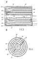
- FIG. 1 is a longitudinal section of the front part of a burner according to the invention;
- FIG. 2 shows a cross-section along the line II-II of FIG. 1;
- FIG. 3 is a longitudinal section of the front part of another burner according to the invention; and
- FIG. 4 shows a cross-section along the line III-III of FIG. 3.
- It should be noted that identical elements shown in the drawings have been indicated with the same reference numeral.
- Referring to FIGS. 1 and 2, a burner, generally indicated with the
reference numeral 10, for the partial combustion of a carbonaceous fuel, such as pulverized coal comprises acentral channel 12 disposed along alongitudinal axis 14, and having adischarge outlet 16 for supplying a finely divided solid fuel (arrow A) in a carrier gas, e.g., nitrogen, carbon dioxide or synthesis gas, to a combustion zone. Concentrically arranged around thecentral channel 12 is a first substantiallyannular channel 18 for an oxidant gas (arrow B) having afree end 20 forming an outlet for said oxidant gas flow into the combustion zone. Advantageously, theoutlet 20 is disposed at an angle of from about 15 to about 60 degrees with respect to thelongitudinal axis 14, so that the issuing stream of oxygen-containing gas will intersect and mix with the stream of solid fuel issuing fromoutlet 16 into the downstream combustion zone. The oxidant gas will be oxygen-containing gas, or optionally a mixture of oxygen-containing gas with a moderator gas such as, e.g., steam or carbon dioxide. Conventional separators are used for radially spacing the channels from each other, for example alignment pins, fins, centering vanes, spacers and other conventional means are used to symmetrically space the channels with respect to each other and to hold same in stable alignment with minimal obstruction to the free flow of the reactant streams. - The
burner 10 further comprises a cylindricalhollow wall member 26 having an enlarged end part forming afront face 28 which is normal to thelongitudinal axis 14 of the burner. The hollow wall member is interiorly provided with spiral flow means 29, which may be somewhat pervious to fluids, but advantageously is a fluid impervious barrier forming aspiral channel 30, said channel having one end operatively connected to supplyconduit 34 for supplying fluid coolant (arrow C) to said spiral channel and having the other end of said spiral channel operatively connected to returnconduit 32 to pass fluid coolant from said channel 30 (arrow D). The supply conduit may be operatively connected to either end of the spiral channel, and the return conduit to the other end, as desired. However, advantageously the supply conduit provides the fluid coolant, particularly a liquid coolant such as tempered water to the outside end ofspiral channel 30. - It is an advantage of the present invention that it permits convective and radiant heat transfer from the combustion downstream of the burner face while avoiding, substantially or altogether, boiling of the coolant liquid within the hollow wall member. The use of high velocity coolant through the spiral channel assures even, low metal temperature in the burner face thereby enabling long life of the burner.
- When water is used as coolant, it is supplied to the hollow wall member at a flow rate sufficiently high that at maximum heat output of the burner the water entering the return conduit will have increased no more than about 5°C and more in particular less than about 3°C. It is found advantageous to employ as coolant tempered water having a temperature in the range below about 210°C.
- During operation of the above described
burner 10 for the gasification of carbonaceous fuel, e.g., pulverized coal by means of oxygen-containing gas, said coal suspended in a carrier fluid, such as, e.g., nitrogen, synthesis gas or carbon dioxide, is passed through thecentral channel 12 tooutlet 16 for introducing the coal into the combustion zone of a reactor arranged downstream of the burner. Simultaneously, oxygen-containing gas is passed throughannular channel 18 tooutlet 20 so that the coal and oxygen-containing gas reactants will be intensively mixed in the reactor space. The mixing of the reactants can be further promoted by a swirling motion imparted to one or both streams by a swirl body of baffles (not shown) in the appropriate channel. To promote stable outflow of coal the cross sectional area available for the coal flow should be kept constant over at least part ofcentral channel 12 of the burner near the outlet. - During operation of the burner for the gasification of pulverized fuel, a temperature moderating gas such as steam, carbon dioxide or nitrogen also may be introduced into the feed line of annular channel so that a mixture of oxygen-containing gas and moderating gas, is conveyed through
annular channel 18 tooutlet 20 to control the temperature and to limit the amount of oxygen as needed. The rate of flow for each of the streams of pulverized fuel, and oxygen-containing gas optionally mixed with temperature moderator gas is controlled by a flow control valve (not shown) in each feedline upstream of the burner. The burner firing rate, i.e., turnup or turndown of the burner, is effected by changing the flow rate for each of the streams while maintaining a substantially constant ratio of atomic oxygen to carbon in the solid feed. Generally an oxygen demand of 0.9 to 1 ton per ton of moisture and ash-free coal is fairly typical of hard coals; for low rank coals 0.7 tons oxygen per ton is more representative. - Referring now to Figs. 3 and 4 a burner is shown wherein arranged concentrically around said first
annular channel 18 is a second substantiallyannular channel 22 for a second gas, which may be oxygen-containing gas, a moderator gas such as, e.g., steam or carbon dioxide, or a mixture or oxygen-containing gas and moderator gas, and havingfree end 24 forming an outlet for a second gas flow into the combustion zone. Saidoutlet 24 will generally be disposed at a similar angle with respect to thelongitudinal axis 14, but advantageously will be more divergent, i.e., less acute when said second annular channel will be used to supply moderating or shielding gas to the combustion zone. The ratio of the cross-sectional area for the second annular channel divided by the cross-sectional area for the first annular channel is in the range from about 0.5 to 2, such as 0.75 to 1.5. - During operation of this burner for the gasification of pulverized fuel a second gas which may be oxygen-containing gas, a temperature moderating gas such as steam, carbon dioxide or nitrogen, or a mixture of oxygen-containing gas and moderating gas, is conveyed through
annular channel 22 tooutlet 24 to supply additional oxygen as needed, and when said second gas flow contains substantial amounts of moderator gas, forms a shield around the jets issuing coal and oxygen. The shield of moderator gas may be advantageous for preventing premature contact of oxygen with the reactor gas, which might result in undesirable complete conversion of the reactor gas. It is preferred to operate by supplying oxygen-containing gas through both channels, at a mean velocity in the range from about 35 to about 100 meters/second, supplying said gas through said first (centermost) annular channel outlet at a somewhat lower velocity than the velocity of gas supplied to the combustion zone through said second annular channel outlet. - The rate of flow for each of the streams of the pulverized fuel, the oxygen-containing gas and of the second gas is controlled by a flow control valve in each feedline to the burner. The burner firing rate, i.e., turnup or turndown of the burner, is effected by changing the flow rate for each of the streams while maintaining a substantially constant ratio of atomic oxygen to carbon in the solid feed. Generally an oxygen demand of 0.9 to 1 ton per ton of moisture and ash-free coal is fairly typical of hard coals; for low rank coals 0.7 tons oxygen per ton is more representative. It is an advantage of the instant burner in addition to its durability that it has a channel for admitting a second gas to the combustion zone that permits great flexibility in supplying the reactants under a wide variety of operational requirements.
- The burner will ordinarily be fabricated of high temperature resistant materials, particularly high temperature resistant metals and alloys and be fabricated by techniques of welding and/or brazing conventionally employed with such materials. For high duty operations the channels and outlets for oxygen-containing gas, which are usually made of metal, may be internally coated with an oxidic coating, such as ZrO₂, or a ceramic, enabling the application of high oxygen-containing gas velocities without the risk of metal combustion by the oxygen.
- The term solid carbonaceous fuel as used herein is intended to include various materials and mixtures thereof from the group of coal, coke from coal, coal liquefaction residues, petroleum coke, soot and particulate solids derived from oil shale, tar sands and pitch. The coal may be of any type, including lignite, sub-bituminous, bituminous and anthracite. The solid carbonaceous fuels are advantageously ground to a particle size so that at least about 90% by weight of the material is less than 90 microns and moisture content is less than about five per cent weight.
- The term "oxygen-containing gas" as used herein is intended to refer to gas containing free oxygen, i.e., uncombined oxygen, and to include air, oxygen-enriched air, i.e., greater than 21 mole % oxygen, and also substantially pure oxygen, i.e., greater than about 95 mole % oxygen, with the remainder comprising gases normally found in air such as nitrogen and the rare gases.
- Various modifications of the invention will become apparent to those skilled in the art from the foregoing description and accompanying drawings. Such modifications are intended to fall within the scope of the appended claims.
Claims (5)
a central channel (12) and outlet (16) for supplying fuel to the combustion zone;
at least one first substantially annular channel (18) disposed coaxially with said central channel (12) and having an outlet (20) to supply an oxidant gas flow to the combustion zone;
a front face (28) disposed at the discharge end of said burner and normal to the longitudinal axis (14) thereof, said front face (28) having a central aperture through which at least said fuel and oxidant gas flow to the combustion zone; said front face (28) comprising a hollow wall member (26) operatively connected to: (a) a supply conduit (34) disposed to supply fluid coolant to the proximate first end of a passageway in said hollow wall member (26); (b) a return conduit (32) disposed to pass fluid coolant proximately from the final end of said passageway; and (c) including spiral flow means (29) defining said passageway disposed within said hollow wall member (26) to cause fluid coolant entering said hollow wall member (26) from said supply conduit (34) to flow in a spiral direction about the longitudinal axis of the burner.
Applications Claiming Priority (4)
| Application Number | Priority Date | Filing Date | Title |
|---|---|---|---|
| US156679 | 1980-06-05 | ||
| US156675 | 1988-02-17 | ||
| US07/156,675 US4887962A (en) | 1988-02-17 | 1988-02-17 | Partial combustion burner with spiral-flow cooled face |
| US07/156,679 US4865542A (en) | 1988-02-17 | 1988-02-17 | Partial combustion burner with spiral-flow cooled face |
Publications (2)
| Publication Number | Publication Date |
|---|---|
| EP0328794A1 EP0328794A1 (en) | 1989-08-23 |
| EP0328794B1 true EP0328794B1 (en) | 1991-05-08 |
Family
ID=26853407
Family Applications (1)
| Application Number | Title | Priority Date | Filing Date |
|---|---|---|---|
| EP19880202798 Expired EP0328794B1 (en) | 1988-02-17 | 1988-12-06 | Partial combustion burner with spiral-flow cooled face |
Country Status (6)
| Country | Link |
|---|---|
| EP (1) | EP0328794B1 (en) |
| JP (1) | JP2627552B2 (en) |
| CN (1) | CN1011617B (en) |
| AU (1) | AU605388B2 (en) |
| CA (1) | CA1308306C (en) |
| DE (1) | DE3862757D1 (en) |
Families Citing this family (28)
| Publication number | Priority date | Publication date | Assignee | Title |
|---|---|---|---|---|
| CN201228965Y (en) | 2007-08-06 | 2009-04-29 | 国际壳牌研究有限公司 | Combustor |
| CN101363623B (en) * | 2007-08-06 | 2010-12-08 | 国际壳牌研究有限公司 | Burner |
| CN101363626B (en) * | 2007-08-06 | 2015-05-20 | 国际壳牌研究有限公司 | Method of manufacturing a burner front face |
| US8070483B2 (en) * | 2007-11-28 | 2011-12-06 | Shell Oil Company | Burner with atomizer |
| CN101909738B (en) | 2008-01-16 | 2013-11-06 | 国际壳牌研究有限公司 | Process to provide a particulate solid material to a pressurised reactor |
| SE532338C2 (en) | 2008-04-22 | 2009-12-15 | Aga Ab | Method and apparatus for combustion of solid phase fuel |
| CN101382292B (en) * | 2008-10-24 | 2010-09-01 | 孙明路 | Alcohol based burning machine, alcohol based combustion nozzle thereof and pneumatic power shearing knife |
| CN103140713A (en) * | 2010-09-16 | 2013-06-05 | 勒舍有限公司 | Solid-fuel-fired hot gas generator having an extended control range |
| KR101892683B1 (en) | 2010-10-01 | 2018-08-29 | 에어 프로덕츠 앤드 케미칼스, 인코오포레이티드 | A burner for the gasification of a solid fuel |
| US9822969B2 (en) | 2010-11-30 | 2017-11-21 | General Electric Company | Fuel injector having tip cooling |
| CN102287825A (en) * | 2011-07-15 | 2011-12-21 | 马鞍山科达洁能股份有限公司 | Burning nozzle and coal-gasifying furnace |
| WO2013010303A1 (en) * | 2011-07-15 | 2013-01-24 | 马鞍山科达洁能股份有限公司 | Burner nozzle and coal gasifier |
| CN102287826B (en) * | 2011-07-15 | 2013-09-11 | 安徽科达洁能股份有限公司 | Combustion nozzle and coal gasification furnace |
| CN103254940A (en) * | 2012-02-16 | 2013-08-21 | 通用电气公司 | A system and a method for cooling a fuel injector |
| CN202835334U (en) | 2012-04-02 | 2013-03-27 | 国际壳牌研究有限公司 | Burner used for gasified solid fuel |
| CN103266951A (en) * | 2012-05-22 | 2013-08-28 | 摩尔动力(北京)技术股份有限公司 | Non-gas-liquid fuel working medium generator for power system |
| EP2743579A1 (en) * | 2012-12-14 | 2014-06-18 | Siemens Aktiengesellschaft | Burner tip and burner |
| CN107033971B (en) * | 2016-02-04 | 2021-01-08 | 清华大学 | Multi-channel combined burner for coal water slurry gasification furnace and coal water slurry gasification furnace |
| CN107022379B (en) * | 2017-05-09 | 2020-05-26 | 哈尔滨工业大学 | Dry coal powder entrained flow gasifier nozzle with water-cooling coil protection |
| CN110577846B (en) * | 2019-09-12 | 2021-02-05 | 杨建平 | Combustion system and burner |
| TWI769612B (en) * | 2020-11-02 | 2022-07-01 | 國立成功大學 | Scroll heating device |
| CN112797420A (en) * | 2020-12-07 | 2021-05-14 | 南京锦泥资源环境科技有限公司 | Waste water mud minimizing is with burning device |
| CN112879902A (en) * | 2021-01-18 | 2021-06-01 | 煤科院节能技术有限公司 | Biomass powder coupled pulverized coal burner and using method thereof |
| CN112856439A (en) * | 2021-01-18 | 2021-05-28 | 煤科院节能技术有限公司 | Combustion processor and method for treating refuse incineration ash |
| CN112856438A (en) * | 2021-01-18 | 2021-05-28 | 煤科院节能技术有限公司 | Organic waste liquid combustion processor and use method thereof |
| CN112856454A (en) * | 2021-01-18 | 2021-05-28 | 煤科院节能技术有限公司 | Exhaust gas treatment device and exhaust gas treatment method |
| CN114621793B (en) * | 2022-03-17 | 2023-06-13 | 张金辉 | Burner of coal gasification equipment |
| CN116477641B (en) * | 2023-02-28 | 2024-04-12 | 安徽泽一科技有限公司 | Production equipment for ammonia synthesis process |
Family Cites Families (7)
| Publication number | Priority date | Publication date | Assignee | Title |
|---|---|---|---|---|
| US3607157A (en) * | 1969-07-23 | 1971-09-21 | Texaco Inc | Synthesis gas from petroleum coke |
| US4443228A (en) * | 1982-06-29 | 1984-04-17 | Texaco Inc. | Partial oxidation burner |
| US4547145A (en) * | 1983-03-09 | 1985-10-15 | Texaco Development Corporation | Combination with a high temperature combustion chamber and top burner |
| US4443230A (en) * | 1983-05-31 | 1984-04-17 | Texaco Inc. | Partial oxidation process for slurries of solid fuel |
| GB8317251D0 (en) * | 1983-06-24 | 1983-07-27 | Shell Int Research | Burner for gasification of solid fuel |
| DE3440088A1 (en) * | 1984-11-02 | 1986-05-07 | Veba Oel Entwicklungs-Gesellschaft mbH, 4650 Gelsenkirchen | BURNER |
| IN167217B (en) * | 1985-04-16 | 1990-09-22 | Dow Chemical Co |
-
1988
- 1988-11-29 JP JP29977288A patent/JP2627552B2/en not_active Expired - Lifetime
- 1988-11-29 AU AU26373/88A patent/AU605388B2/en not_active Expired
- 1988-11-30 CN CN 88108098 patent/CN1011617B/en not_active Expired
- 1988-12-06 DE DE8888202798T patent/DE3862757D1/en not_active Expired - Lifetime
- 1988-12-06 EP EP19880202798 patent/EP0328794B1/en not_active Expired
- 1988-12-06 CA CA000585081A patent/CA1308306C/en not_active Expired - Lifetime
Also Published As
| Publication number | Publication date |
|---|---|
| JPH028603A (en) | 1990-01-12 |
| CN1011617B (en) | 1991-02-13 |
| AU2637388A (en) | 1989-08-17 |
| CN1035172A (en) | 1989-08-30 |
| CA1308306C (en) | 1992-10-06 |
| JP2627552B2 (en) | 1997-07-09 |
| EP0328794A1 (en) | 1989-08-23 |
| DE3862757D1 (en) | 1991-06-13 |
| AU605388B2 (en) | 1991-01-10 |
Similar Documents
| Publication | Publication Date | Title |
|---|---|---|
| US4865542A (en) | Partial combustion burner with spiral-flow cooled face | |
| US4887962A (en) | Partial combustion burner with spiral-flow cooled face | |
| EP0328794B1 (en) | Partial combustion burner with spiral-flow cooled face | |
| US4858538A (en) | Partial combustion burner | |
| EP0107225B1 (en) | Process and burner for the partial combustion of solid fuel | |
| US4458607A (en) | Process and burner for the partial combustion of finely divided solid fuel | |
| CA1190046A (en) | Partial oxidation burner | |
| EP0120517B1 (en) | Burner and process for the partial combustion of solid fuel | |
| US4353712A (en) | Start-up method for partial oxidation process | |
| EP2176590B1 (en) | Burner | |
| EP0127273A2 (en) | Burner and partial oxidation process for slurries of solid fuel | |
| US4400179A (en) | Partial oxidation high turndown apparatus | |
| US4386941A (en) | Process for the partial oxidation of slurries of solid carbonaceous fuel | |
| EP1274958B1 (en) | Threaded heat shield for burner nozzle face | |
| US4736693A (en) | Partial combustion burner with heat pipe-cooled face | |
| US4392869A (en) | High turndown partial oxidation process | |
| US4351647A (en) | Partial oxidation process | |
| CA1269842A (en) | Process for producing synthesis gas from hydrocarbon fuel | |
| US4351645A (en) | Partial oxidation burner apparatus | |
| US4371379A (en) | Partial oxidation process using a swirl burner | |
| US4364744A (en) | Burner for the partial oxidation of slurries of solid carbonaceous fuels | |
| US4479810A (en) | Partial oxidation system | |
| EP0021461B2 (en) | Process and burner for the gasification of solid fuel | |
| US4371378A (en) | Swirl burner for partial oxidation process | |
| EP0108425B1 (en) | Burner for the partial combustion of finely divided solid fuel |
Legal Events
| Date | Code | Title | Description |
|---|---|---|---|
| PUAI | Public reference made under article 153(3) epc to a published international application that has entered the european phase |
Free format text: ORIGINAL CODE: 0009012 |
|
| AK | Designated contracting states |
Kind code of ref document: A1 Designated state(s): DE GB IT NL SE |
|
| 17P | Request for examination filed |
Effective date: 19891213 |
|
| 17Q | First examination report despatched |
Effective date: 19900731 |
|
| GRAA | (expected) grant |
Free format text: ORIGINAL CODE: 0009210 |
|
| AK | Designated contracting states |
Kind code of ref document: B1 Designated state(s): DE GB IT NL SE |
|
| REF | Corresponds to: |
Ref document number: 3862757 Country of ref document: DE Date of ref document: 19910613 |
|
| ITF | It: translation for a ep patent filed | ||
| PLBE | No opposition filed within time limit |
Free format text: ORIGINAL CODE: 0009261 |
|
| STAA | Information on the status of an ep patent application or granted ep patent |
Free format text: STATUS: NO OPPOSITION FILED WITHIN TIME LIMIT |
|
| 26N | No opposition filed | ||
| EAL | Se: european patent in force in sweden |
Ref document number: 88202798.0 |
|
| PGFP | Annual fee paid to national office [announced via postgrant information from national office to epo] |
Ref country code: SE Payment date: 19971113 Year of fee payment: 10 |
|
| PG25 | Lapsed in a contracting state [announced via postgrant information from national office to epo] |
Ref country code: SE Free format text: LAPSE BECAUSE OF NON-PAYMENT OF DUE FEES Effective date: 19981207 |
|
| REG | Reference to a national code |
Ref country code: GB Ref legal event code: IF02 |
|
| PGFP | Annual fee paid to national office [announced via postgrant information from national office to epo] |
Ref country code: NL Payment date: 20071228 Year of fee payment: 20 |
|
| PGFP | Annual fee paid to national office [announced via postgrant information from national office to epo] |
Ref country code: IT Payment date: 20071221 Year of fee payment: 20 |
|
| PGFP | Annual fee paid to national office [announced via postgrant information from national office to epo] |
Ref country code: GB Payment date: 20071122 Year of fee payment: 20 |
|
| PGFP | Annual fee paid to national office [announced via postgrant information from national office to epo] |
Ref country code: DE Payment date: 20071214 Year of fee payment: 20 |
|
| REG | Reference to a national code |
Ref country code: GB Ref legal event code: PE20 Expiry date: 20081205 |
|
| PG25 | Lapsed in a contracting state [announced via postgrant information from national office to epo] |
Ref country code: NL Free format text: LAPSE BECAUSE OF EXPIRATION OF PROTECTION Effective date: 20081206 |
|
| PG25 | Lapsed in a contracting state [announced via postgrant information from national office to epo] |
Ref country code: GB Free format text: LAPSE BECAUSE OF EXPIRATION OF PROTECTION Effective date: 20081205 |