EP0328626B1 - Mist eliminator module and a method for self-cleaning of the same - Google Patents
Mist eliminator module and a method for self-cleaning of the same Download PDFInfo
- Publication number
- EP0328626B1 EP0328626B1 EP88908059A EP88908059A EP0328626B1 EP 0328626 B1 EP0328626 B1 EP 0328626B1 EP 88908059 A EP88908059 A EP 88908059A EP 88908059 A EP88908059 A EP 88908059A EP 0328626 B1 EP0328626 B1 EP 0328626B1
- Authority
- EP
- European Patent Office
- Prior art keywords
- blades
- mist eliminator
- module
- accordance
- blade
- Prior art date
- Legal status (The legal status is an assumption and is not a legal conclusion. Google has not performed a legal analysis and makes no representation as to the accuracy of the status listed.)
- Expired - Lifetime
Links
- 239000003595 mist Substances 0.000 title claims abstract description 59
- 238000004140 cleaning Methods 0.000 title claims abstract description 23
- 238000000034 method Methods 0.000 title claims description 4
- 125000006850 spacer group Chemical group 0.000 claims abstract description 51
- XLYOFNOQVPJJNP-UHFFFAOYSA-N water Substances O XLYOFNOQVPJJNP-UHFFFAOYSA-N 0.000 claims abstract description 22
- 239000007787 solid Substances 0.000 claims abstract description 18
- 239000007921 spray Substances 0.000 claims abstract description 13
- 239000000463 material Substances 0.000 claims abstract description 8
- 239000000835 fiber Substances 0.000 claims abstract description 3
- 239000007788 liquid Substances 0.000 claims description 10
- 238000011144 upstream manufacturing Methods 0.000 claims description 5
- 239000013536 elastomeric material Substances 0.000 claims description 2
- 229920001084 poly(chloroprene) Polymers 0.000 claims description 2
- 239000008400 supply water Substances 0.000 claims 2
- 229920000728 polyester Polymers 0.000 claims 1
- 238000005507 spraying Methods 0.000 claims 1
- 239000007789 gas Substances 0.000 description 21
- 238000006477 desulfuration reaction Methods 0.000 description 4
- 230000023556 desulfurization Effects 0.000 description 4
- UGFAIRIUMAVXCW-UHFFFAOYSA-N Carbon monoxide Chemical compound [O+]#[C-] UGFAIRIUMAVXCW-UHFFFAOYSA-N 0.000 description 3
- 238000009825 accumulation Methods 0.000 description 3
- 239000003546 flue gas Substances 0.000 description 3
- 230000000149 penetrating effect Effects 0.000 description 3
- 238000005201 scrubbing Methods 0.000 description 3
- 235000019687 Lamb Nutrition 0.000 description 2
- RAHZWNYVWXNFOC-UHFFFAOYSA-N Sulphur dioxide Chemical compound O=S=O RAHZWNYVWXNFOC-UHFFFAOYSA-N 0.000 description 2
- OSGAYBCDTDRGGQ-UHFFFAOYSA-L calcium sulfate Chemical compound [Ca+2].[O-]S([O-])(=O)=O OSGAYBCDTDRGGQ-UHFFFAOYSA-L 0.000 description 2
- 238000004519 manufacturing process Methods 0.000 description 2
- 230000015572 biosynthetic process Effects 0.000 description 1
- 159000000007 calcium salts Chemical class 0.000 description 1
- GBAOBIBJACZTNA-UHFFFAOYSA-L calcium sulfite Chemical compound [Ca+2].[O-]S([O-])=O GBAOBIBJACZTNA-UHFFFAOYSA-L 0.000 description 1
- 235000010261 calcium sulphite Nutrition 0.000 description 1
- 239000003245 coal Substances 0.000 description 1
- 239000011248 coating agent Substances 0.000 description 1
- 238000000576 coating method Methods 0.000 description 1
- 230000002542 deteriorative effect Effects 0.000 description 1
- 229910003460 diamond Inorganic materials 0.000 description 1
- 239000010432 diamond Substances 0.000 description 1
- 239000011152 fibreglass Substances 0.000 description 1
- 239000003517 fume Substances 0.000 description 1
- 229910052751 metal Inorganic materials 0.000 description 1
- 239000002184 metal Substances 0.000 description 1
- 230000000737 periodic effect Effects 0.000 description 1
- 239000004033 plastic Substances 0.000 description 1
- 229920003023 plastic Polymers 0.000 description 1
- 229920001225 polyester resin Polymers 0.000 description 1
- 239000004645 polyester resin Substances 0.000 description 1
- 229920000642 polymer Polymers 0.000 description 1
- 238000001556 precipitation Methods 0.000 description 1
- 238000009877 rendering Methods 0.000 description 1
- 229920005989 resin Polymers 0.000 description 1
- 239000011347 resin Substances 0.000 description 1
- 238000007790 scraping Methods 0.000 description 1
- 238000000926 separation method Methods 0.000 description 1
- 239000002002 slurry Substances 0.000 description 1
Images


Classifications
-
- B—PERFORMING OPERATIONS; TRANSPORTING
- B01—PHYSICAL OR CHEMICAL PROCESSES OR APPARATUS IN GENERAL
- B01D—SEPARATION
- B01D45/00—Separating dispersed particles from gases or vapours by gravity, inertia, or centrifugal forces
- B01D45/04—Separating dispersed particles from gases or vapours by gravity, inertia, or centrifugal forces by utilising inertia
- B01D45/08—Separating dispersed particles from gases or vapours by gravity, inertia, or centrifugal forces by utilising inertia by impingement against baffle separators
-
- B—PERFORMING OPERATIONS; TRANSPORTING
- B01—PHYSICAL OR CHEMICAL PROCESSES OR APPARATUS IN GENERAL
- B01D—SEPARATION
- B01D45/00—Separating dispersed particles from gases or vapours by gravity, inertia, or centrifugal forces
- B01D45/04—Separating dispersed particles from gases or vapours by gravity, inertia, or centrifugal forces by utilising inertia
-
- B—PERFORMING OPERATIONS; TRANSPORTING
- B01—PHYSICAL OR CHEMICAL PROCESSES OR APPARATUS IN GENERAL
- B01D—SEPARATION
- B01D45/00—Separating dispersed particles from gases or vapours by gravity, inertia, or centrifugal forces
- B01D45/04—Separating dispersed particles from gases or vapours by gravity, inertia, or centrifugal forces by utilising inertia
- B01D45/08—Separating dispersed particles from gases or vapours by gravity, inertia, or centrifugal forces by utilising inertia by impingement against baffle separators
- B01D45/10—Separating dispersed particles from gases or vapours by gravity, inertia, or centrifugal forces by utilising inertia by impingement against baffle separators which are wetted
Definitions
- the present invention relates to mist eliminator modules used in flue gas desulfurization exhaust streams and other gas streams having particulates and droplets which would tend to clog or scale the blades of a mist eliminator module.
- a mist eliminator also known as a droplet collector, is used to remove suspended liquids or droplets from a gas stream.
- one or more mist eliminator modules or sections are installed in a vertical droplet scrubbing tower or in a horizontal scrubber casing.
- a mist eliminator module is usually a group of closely spaced parallel zig-zag eliminator blades fastened together. Liquid droplets impinge on and are deposited on the blades and thereby removed from the gas stream.
- the gas stream may contain solid particulates and/or liquid droplets that react with gaseous components in the gas stream to precipitate solids.
- the exhaust stream of a flue gas desulfurization unit may contain droplets of a slurry of water and calcium salts which will react with residual sulfur dioxide in the gas stream to precipitate calcium sulfite or calcium sulfate on the mist eliminator blades.
- These deposited solids (usually referred to as "scale") reduce the mist eliminator droplet removal efficiency and eventually clog the passages between the blades.
- mist eliminator module that is easily cleaned, or, preferably, self cleaning, to prevent the formation of scale on the blades by the precipitation and build-up of solids.
- a resilient support holds a captive edge portion of the blades in spaced alignment.
- a detachable spacer holds a free edge portion of the blades in spaced alignment.
- the blades may be manually cleaned in place by removing the spacer and separating each blade from adjacent blades, and cleaning each side of the blade.
- the blade module may also be made self-cleaning by operating the mist eliminator chamber with the water spray running and the support bar removed so that the blades flex and vibrate sufficiently to flake off any accumulated solids.
- FIGURE 1 is an end view of a mist eliminator module of the present invention.
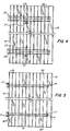
- FIGURE 4 a view showing at least one spacer bar mounted on the blades of the mist eliminator module.
- FIGURE 5 is a view showing at least one rod extending through the captive edge portions of the blades of the mist eliminator module.
- FIGURE 6 is a cross section of the free edge portions of a mist eliminator module of the present invention along the line 6-6 of FIGURE 1.
- the blades 12 preferably comprise a fiberglass core covered with a thick polyester resin coating and a surfacing veil to insure a smooth resin-rich surface on each blade 12.
- the blades may be made of any other smooth materials such as other polymeric compounds or metal.
- the smooth surface prevents the accumulation of solids in the pits and fissures of blade surfaces made from other types of materials or according to prior art designs.
- the blades 12 are held together in the selected spacing by two supporting elements.
- the first element is a support which resiliently holds a captive edge portion 16 of the blades 12 in spaced alignment.
- the support comprises at least one support rod 14 which extends through apertures 15 in captive edge portions 16 of each of the blades 12.
- the rod 14 will preferably be a one-half inch (1.2 cm) diameter rod.
- the apertures 15 are aligned to form a passage from one side of the module to an opposite side, so that the rod 14 may traverse the entire module 10.
- the captive edges 16 of the blades 12 are perpendicular to the rod 14.
Landscapes
- Chemical & Material Sciences (AREA)
- Chemical Kinetics & Catalysis (AREA)
- Treating Waste Gases (AREA)
- Separating Particles In Gases By Inertia (AREA)
- Gas Separation By Absorption (AREA)
- Heat-Exchange Devices With Radiators And Conduit Assemblies (AREA)
- Filtering Of Dispersed Particles In Gases (AREA)
Abstract
Description
- The present invention relates to mist eliminator modules used in flue gas desulfurization exhaust streams and other gas streams having particulates and droplets which would tend to clog or scale the blades of a mist eliminator module.
- A mist eliminator, also known as a droplet collector, is used to remove suspended liquids or droplets from a gas stream. Typically, one or more mist eliminator modules or sections are installed in a vertical droplet scrubbing tower or in a horizontal scrubber casing. A mist eliminator module is usually a group of closely spaced parallel zig-zag eliminator blades fastened together. Liquid droplets impinge on and are deposited on the blades and thereby removed from the gas stream.
- In heavy duty applications, such as the exhaust stream from a flue gas desulfurization unit (such units are frequently used to treat the exhaust of coal fired boilers and paper mill exhaust fumes), the gas stream may contain solid particulates and/or liquid droplets that react with gaseous components in the gas stream to precipitate solids. For example, the exhaust stream of a flue gas desulfurization unit may contain droplets of a slurry of water and calcium salts which will react with residual sulfur dioxide in the gas stream to precipitate calcium sulfite or calcium sulfate on the mist eliminator blades. These deposited solids (usually referred to as "scale") reduce the mist eliminator droplet removal efficiency and eventually clog the passages between the blades.
- It is desirable therefore to provide for a mist eliminator module that is easily cleaned, or, preferably, self cleaning, to prevent the formation of scale on the blades by the precipitation and build-up of solids.
- Several designs have been proposed to allow for the periodic cleaning of mist eliminator blades (also referred to in the art as plates). One such design, in US-A-2 752 005 to Avera for an Eliminator Plate Assembly for Air Washers, discloses a clip at one end of each plate, which is hooked over a bar so that the plate hangs from the bar and swings freely so that a plate may be easily spread apart from an adjacent plate. At the other end of the plate a slotted spacer bar holds the other ends of the plates in position, but can be detached for cleaning of the plates.
- It has been found in actual use with the exhaust streams of desulfurization units that structures such as that used by Avera, US-A-2752005, quickly become clogged, rendering the mist eliminator unit ineffective. In particular, the hooked ends quickly accumulate solids and scale. Therefore, the assembly shown in Avera, US-A-2752005, will have an excessive amount of cleaning downtime. Furthermore, due to the nature of the clip and bar combination used to provide a pivot, the invention shown in Avera is difficult to use when inverted, that is, when the pivot end of the plates is located on the bottom side of the plates. In such an orientation the plates are difficult to realign after cleaning so that the spacer bar is fitted onto the free ends of the plates.
- US-A- 3 276 193 to Lamb for an Eliminator Plate Assembly for Air Washers discloses an assembly in which the hooked ends of plates are fitted into matching hooks of a core framework.
- The Lamb invention, US-A-3276193, has also been found to be subject to excessive clogging of the blades in heavy duty applications. The hooked ends of the blades and their mountings quickly accumulate precipitated solids and scale during use, creating the need for frequent cleaning. Furthermore, it has been found that when structures such as that disclosed by Lamb, US-A-3276193, are used in a vertical gaseous flow environment such as in a tower, that droplets removed from the gas stream will collect in the hooked ends of the blades, and this collected liquid will be reentrained in the gas stream.
- US-A- 3 864 110 to Wyman for a Support Assembly For Eliminator Blades discloses an assembly in which the edges of blades are seated in grooves formed in support bars situated at the top, bottom, and lateral edges of each blade. However, no provision is made in this design for separating individual blades like the pages of a book to clean them.
- US-A- 3 870 488 to Arndt for a Liquid Eliminator discloses fitting the hooked ends of a blade into a slotted support bracket. The structure disclosed in Arndt has been found to be extremely prone to clogging and solids accumulation in heavy duty use. The hooked ends of the blades and their supports quickly accumulate both liquids and solids in heavy duty service. These accumulated solids and scale must be manually removed, and this may only be accomplished by a complete disassembly of the mist eliminator. Furthermore, if the invention of Arndt, US-A-3870488, is used in a vertical gaseous flow environment such as in a tower, the various trapping vanes and deflectors formed on the blades will fill with trapped droplets leading to reentrainment of the droplets, giving a low droplet removal efficiency.
- To reduce the problem of clogging by particulates, several inventors have suggested the use of an intermittent or continuous wash water spray on the eliminator blades. For example, in US-A- 4 053 292 to Schneider for a Gas Scrubbing Plant, an intermittent 10 second rinse cycle for each hour of operation is recommended to keep plates clean. US-A-4251242 to Ito for a Mist Eliminator also discloses the use of a wash water spray.
- The prior art thus has focused on various blade holding frameworks which use a pivoting hook and rod combination to allow access to the plates for cleaning. This type of mounting has been found to be subject to rapid clogging and deteriorating efficiency in heavy duty applications, and has also been found to lead to reentrainment of collected liquid when used in a vertical flow tower. The prior art does not provide for a blade module which both obviates solid accumulation and which may be readily cleaned in place either manually or by a method of self-cleaning.
- The present invention relates to a mist eliminator blade module which may be cleaned in place either manually or by a method of self cleaning.
- The invention consists in a mist eliminator module for removing liquid components of a gas stream, comprising: a plurality of mist eliminator blades formed from a smooth material, each blade having a captive edge portion and a free edge portion, and each blade being in substantial alignment with adjacent blades; a resilient support for holding captive edge portions of said blades in spaced alignment; and a detachable spacer for holding free edge portions of said blades in spaced alignment; whereby said blades may be readily separated from adjacent blades after detaching said spacer.
- The eliminator blades have no hooks or protrusions.
Preferably, the blades are formed from a fiber reinforced polymeric material. - A resilient support holds a captive edge portion of the blades in spaced alignment.
- Preferably the support is at least one rod extending through aligned apertures in a captive edge portion of adjacent blades. A plurality of resilient spacers are located between the blades to allow the blades to be flexibly separated, and a holding means holds the rod, blades and spacers together.
- A detachable spacer holds a free edge portion of the blades in spaced alignment.
- Preferably the spacer is at least one rigid spacer bar, having a plurality of slots in one face, attached to the free edge portion of the blades by inserting the free edge portions into the spacer bar slots.
- A water spray may be directed onto the blades to form a continuous film of water on the blades.
- The blades may be manually cleaned in place by removing the spacer and separating each blade from adjacent blades, and cleaning each side of the blade. The blade module may also be made self-cleaning by operating the mist eliminator chamber with the water spray running and the support bar removed so that the blades flex and vibrate sufficiently to flake off any accumulated solids.
- FIGURE 1 is an end view of a mist eliminator module of the present invention.
- FIGURE 2 is a cut-away view of a mist eliminator tower showing a mist eliminator module and a water spray.
- FIGURE 3 is a detail end view of the rod and tubular flexible spacers showing blade movement when the rigid spacer is removed.
- FIGURE 4 a view showing at least one spacer bar mounted on the blades of the mist eliminator module.
- FIGURE 5 is a view showing at least one rod extending through the captive edge portions of the blades of the mist eliminator module.
- FIGURE 6 is a cross section of the free edge portions of a mist eliminator module of the present invention along the line 6-6 of FIGURE 1.
- In accordance with the invention, a
mist eliminator module 10 is shown. The mist eliminator has a plurality of thin, smooth zig-zagmist eliminator blades 12 held parallel to each other and spaced sufficiently closely together that there are no straight line paths through the module in the direction of the gas flow shown by arrow A. This spacing ensures that a gas stream passing through the mist eliminator module must change direction at least once in the module. The entrained liquid in the gas stream will impinge on and be caught by the blade surfaces. In the embodiment shown, theblades 12 are four bend blades. However, the present invention is applicable to two bend or three bend blades and other types of blades as well. - The
blades 12 preferably comprise a fiberglass core covered with a thick polyester resin coating and a surfacing veil to insure a smooth resin-rich surface on eachblade 12. However, the blades may be made of any other smooth materials such as other polymeric compounds or metal. The smooth surface prevents the accumulation of solids in the pits and fissures of blade surfaces made from other types of materials or according to prior art designs. - The
blades 12 are held together in the selected spacing by two supporting elements. The first element is a support which resiliently holds acaptive edge portion 16 of theblades 12 in spaced alignment. Preferably, the support comprises at least onesupport rod 14 which extends throughapertures 15 incaptive edge portions 16 of each of theblades 12. Therod 14 will preferably be a one-half inch (1.2 cm) diameter rod. Theapertures 15 are aligned to form a passage from one side of the module to an opposite side, so that therod 14 may traverse theentire module 10. The captive edges 16 of theblades 12 are perpendicular to therod 14. - A plurality of resilient
tubular spacers 18 are fitted over therod 14 between theblades 12. Theresilient spacers 18 are preferably composed of an elastomeric material such as neoprene rubber. - A holding means is supplied to hold the
blades 12,rod 14 andspacers 18 together. Preferably the holding means comprises threaded nuts 17 fastened onto threaded ends of therod 14 to hold theblade module 10 together. - The second support element is a detachable spacer for holding a
free edge portion 24 of theblades 12 in spaced alignment. Preferably, the spacer comprises at least one rigidhollow spacer bar 20 havingslots 22 cut in one face. Thefree edge portions 24 of theblades 12 fit into theslots 22, which hold thefree edges 24 in the selected spacing. Thespacer bar 20 may have a variety of cross-sectional shapes, although a diamond shape, shown in FIGURE 6, is the preferred embodiment. - The
spacer bar 20 is secured to theblades 12 by a hold-down plate 25 which is fastened to theblades 12 by screws and nuts 27. - In the preferred embodiment, the
captive edge portion 16 and thefree edge portion 24 are flat portions of ablade 12 which are located in the path of gas flow shown by arrow A. Thecaptive edge portion 16 thus presents a straight edge through which therod 14 may be perpendicularly located. Thefree edge portion 24 presents a straight edge onto which thespacer bar 20 may be mounted. It should be noted that therod 14 andspacer bar 20 are thus generally located in the gas flow path shown by arrow A. This selection of straight edges as the captive and free edge portions minimizes the costs and ease of production and assures flexibility in the mist eliminator module. - However, an alternative embodiment may be employed in which the captive edge portion is located at one edge of each blade in the zig-zag portion of the blade, shown as 30 in FIGURES 1, 2 and 5. A free edge portion would then be located on the opposite zig-zag edge, as shown at 32 in FIGURE 5. This embodiment presents an equally effective mist eliminator module as the previously described preferred embodiment. However, this embodiment will generally be more costly to manufacture, due to the need to locate holes for the
rod 14 in the bends or zig-zag portions of the blades, and the need to cut V-shaped or angled slots in thespacer bar 20. - The design of the
module 10 allows for easy accessibility to and cleaning of theblades 12 by removing thespacer bar 20, and cleaning by mechanical scrubbing or scraping eachblade 12. Theblades 12 are held in alignment by therod 14 andspacers 18, but can be easily separated like the pages of a book. The ease of separation is due to the use of theresilient spacers 18 covering therod 14. Some side to side movement of the blades may also be the result of the flexibility of the blade itself. Theresilient spacers 18 serve to hold theblades 12 in their proper spacing during use, but, also allow the blades to be separated for cleaning. The present invention allows access to each side of the blade, as shown by the range of movement for eachblade 12 indicated by Arrow B in FIGURE 3. - The
mist eliminator module 10 may be circular or rectangular, depending on the cross-sectional shape of the mist eliminator chamber; for instance, themist eliminator tower 34 shown in FIGURE 2 has a square cross-section. - The
mist eliminator module 10 may be used in both horizontal flow gas streams and vertical flow gas streams without the clogging or reentrainment problems of prior art devices. In either case, the preferred embodiment of themodule 10 will be located so that the supporting elements are located at the inlet and outlet ends of the module. In a horizontal flow gas stream themodule 10 will be oriented such that the at least onesupport rod 14 and the at least onespacer bar 20 are located at opposite sides of themodule 10. In a vertical flow gas stream themodule 10 will be oriented such that the at least onesupport rod 14 and the at least onespacer bar 20 are located at the top and bottom of themodule 10. - The
module 10 is effective in either of two orientations relative to both a horizontal and a vertical gas stream. Themodule 10 may be mounted with therod 14 penetrating the inlet edges of the blades 12 (that is, the upstream edges) and with thesupport bar 20 positioned on the outlet edges (the downstream edges) of theblades 12. This orientation is shown in FIGURE 1 where the module is oriented relative to the direction of gas flow shown by Arrow A with therod 14 penetrating the upstream edge. Alternatively, thesupport bar 20 may be located in front of the leading edges of theblades 12, with therod 14 penetrating the trailing edges of theblades 12. The choice of orientations allows for in-place cleaning of themodule 10 from either end of themodule 10. In a vertical flow tower, the module may be cleaned either from above or below the module, depending on which orientation is selected. In a horizontal flow casing, the module may be cleaned from either side of the module, depending on which orientation is chosen. The choice of module orientation may be made depending on the size and location of access to the module inside the mist eliminator chamber. - In either orientation the module can be easily placed into operation after cleaning. In one vertical orientation where
rod 14 penetrates the leading edges of theblades 12, thespacers 18 keep theblades 12 upright so that the bladefree edges 24 may be fitted into theslots 22 of thespacer bar 20 without aligning theblades 12 with a comb or other devices. In the alternate vertical orientation, theblades 12 hang freely from therod 14, allowing thespacer bar 20 to be quickly attached without aligning theblades 12 with a comb. - The frequency of manual cleaning can be reduced by providing a constant or intermittent spray of water over the mist eliminator blades to coat the
blades 12 with a film of water as shown in FIGURE 2. The water film rinses off any accumulating solids from the blades, to insure the continuing droplet removal efficiency of the blades. It has been found thatwater spray nozzles 36 providing water droplets having a diameter of 200 to 300 micrometers at a nozzle pressure of at least 40 psig (2.8·10⁵Pa) with water flow rates of between .1 to .5 gallons per minute per square foot (3.8·10⁻⁴ m³ to 1.9·10⁻³ m³ per min per 929.03 cm²) of tower cross-sectional area provide optimal cleaning. Thewater spray nozzles 32 should be directed at themodules 10 from the upstream side of the leading edges of theblades 12. - It has been found that the module of the present invention may be made to be self cleaning by removing the
spacer bar 20 from the module and operating the mist eliminator chamber to provide an air flow through the module sufficient to cause the blades to flex and vibrate. The flexing and vibration results because of the flexibility of theplastic blades 12 in combination with theresilient spacers 18. This unique combination gives themodule 10 the capacity to the flex and vibrate, causing accumulated solids to flake off of the blade surfaces. Preferably, a water spray is also provided as above described to rinse off the flaking solids and to flex and vibrate the blades. - Therefore, the present invention provides an improved mist eliminator blade module, which is easily cleaned, and which can be made to be self-cleaning in place.
Claims (15)
- A mist eliminator module (10) for removing liquid components of a gas stream, comprising:
a plurality of mist eliminator blades (12) formed from a smooth material, each blade having a captive edge portion (16) and a free edge portion (24), and each blade (12) being in substantial alignment with adjacent blades;
a resilient support (14, 18) for holding captive edge portions of said blades (12) in spaced alignment; and
a detachable spacer (20) for holding free edge portions of said blades in spaced alignment;
whereby said blades may be readily separated from adjacent blades after detaching said spacer (20). - A mist eliminator module in accordance with claim 1 wherein said resilient support (14, 18) comprises:
at least one support rod (14) extending through aligned apertures in the captive edge portions of said blades;
a plurality of resilient spacers (18) fitted onto said rod between said blades; and
a securing mechanism (17) for holding the said blades and spacers in secured alignment. - A mist eliminator module in accordance with claim 2 wherein each end of said at least one support rod (14) is threaded and wherein said securing mechanism comprises threaded nuts (17) threaded onto said support rod ends.
- A mist eliminator module in accordance with claims 1, 2 or 3 wherein said spacer comprises at least one rigid spacer bar (20) having a plurality of slots (22) formed in one edge for receiving said free edge portions of said blades.
- A mist eliminator module in accordance with claim 4 wherein said spacer bar (20) is hollow.
- A mist eliminator module in accordance with any preceding claim wherein said module is oriented relative to said gas stream such that said support and said captive edge portions (16) of said blades (12) are located downstream of said spacer (20) and said free edge portions of said blades.
- A mist eliminator module in accordance with any of claims 1 to 5 wherein said module is oriented relative to said gas stream such that said support and said captive edge portions (16) of said blades (12) are located upstream of said spacer (20) and said free end portions of said blades.
- A mist eliminator module in accordance with any of claims 2 to 7 wherein said resilient spacers (18) comprise an elastomeric material.
- A mist eliminator module in accordance with claim 8 wherein said resilient spacers (18) comprise neoprene rubber.
- A mist eliminator module in accordance with any preceding claim wherein said mist eliminator blades (12) comprise a polymeric material.
- A mist eliminator module in accordance with claim 10 wherein said mist eliminator blades (12) comprise a fiber reinforced polyester material.
- A mist eliminator assembly comprising a mist eliminator module in accordance with any preceding claim, and further comprising:
a water spraying device (36) located adjacent said module to spray water on said blades to form a water film on said blades. - A mist eliminator assembly in accordance with claim 12 wherein said device comprises a nozzle (36) located upstream of said module, and is adapted to supply water droplets having a diameter of 200 to 300 micrometers.
- A mist eliminator assembly in accordance with claim 13 wherein said nozzle is adapted to supply water at a pressure of at least 2.8 x 10⁵ Pa/cm²(40 psig).
- A method of self-cleaning deposited solids from the blades of a mist eliminator module according to any preceding claim comprising the steps of:
removing said detachable spacer from said module;
directing a spray of water droplets having a diameter of 200 to 300 micrometers at a pressure of at least 2.8 x 10⁵ Pa/cm² (40 psig) on said blades; and
flowing air at an effective volume and velocity through said mist eliminator module to induce flexing and vibration of said blades sufficient to dislodge said deposited solids.
Applications Claiming Priority (2)
| Application Number | Priority Date | Filing Date | Title |
|---|---|---|---|
| US82053 | 1987-08-05 | ||
| US07/082,053 US4784674A (en) | 1987-08-05 | 1987-08-05 | Mist eliminator module and a method for self-cleaning of the same |
Publications (3)
| Publication Number | Publication Date |
|---|---|
| EP0328626A1 EP0328626A1 (en) | 1989-08-23 |
| EP0328626A4 EP0328626A4 (en) | 1989-11-07 |
| EP0328626B1 true EP0328626B1 (en) | 1993-03-24 |
Family
ID=22168748
Family Applications (1)
| Application Number | Title | Priority Date | Filing Date |
|---|---|---|---|
| EP88908059A Expired - Lifetime EP0328626B1 (en) | 1987-08-05 | 1988-07-29 | Mist eliminator module and a method for self-cleaning of the same |
Country Status (7)
| Country | Link |
|---|---|
| US (1) | US4784674A (en) |
| EP (1) | EP0328626B1 (en) |
| JP (1) | JP2660859B2 (en) |
| CA (1) | CA1327534C (en) |
| DE (1) | DE3879672T2 (en) |
| ES (1) | ES2007985A6 (en) |
| WO (1) | WO1989000882A1 (en) |
Families Citing this family (23)
| Publication number | Priority date | Publication date | Assignee | Title |
|---|---|---|---|---|
| DE4041165C1 (en) * | 1990-12-21 | 1992-05-27 | Deutsche Babcock Anlagen Ag, 4200 Oberhausen, De | Drop separator of gas washed - which is cleaned by water jets from nozzle pipes positioned perpendicular to lamellae packs mounted on supports |
| US5203894A (en) * | 1992-04-03 | 1993-04-20 | Munters Corporation | Mist eliminator blade spacer |
| US6003434A (en) * | 1995-06-19 | 1999-12-21 | Foerster; Malte E.C. | Process and device for influencing liquid drops in a gas stream |
| AT402264B (en) * | 1995-09-07 | 1997-03-25 | Austrian Energy & Environment | METHOD AND DEVICE FOR WET SEPARATION OF ACID GASES |
| US6083302A (en) * | 1998-08-13 | 2000-07-04 | Abb Environmental Systems, Division Of Abb Flakt, Inc. | Mist eliminator for wet gas scrubbing |
| US20060000360A1 (en) * | 2004-06-30 | 2006-01-05 | Ming-Hwa Shou | Indoor air circulation sterilizing device |
| DE102005056543B4 (en) * | 2005-11-28 | 2016-01-14 | Rea Plastik Tech Gmbh | Mist separator for a gas scrubber |
| US7674304B2 (en) * | 2008-06-26 | 2010-03-09 | Brentwood Industries, Inc. | Drift eliminator with formed beveled tip |
| US7686862B1 (en) * | 2008-09-22 | 2010-03-30 | Peerless Mfg. Co. | Composite vane and method of manufacture |
| DE202008016962U1 (en) * | 2008-12-20 | 2010-05-27 | Rehau Ag + Co | droplet |
| RU2471533C2 (en) * | 2010-09-15 | 2013-01-10 | Российская Федерация, от имени которой выступает Министерство промышленности и торговли Российской Федерации (Минпромторг России) | Air cleaner for ship power planes |
| US20130255289A1 (en) * | 2012-03-30 | 2013-10-03 | Hamilton Sundstrand Corporation | Flash tank eliminator |
| US9993760B2 (en) * | 2015-08-07 | 2018-06-12 | Big Heart Pet, Inc. | Particle separator systems and processes for improving food safety |
| US11752465B2 (en) * | 2016-11-09 | 2023-09-12 | Schubert Environmental Equipment, Inc. | Wet scrubber apparatus |
| US10480816B2 (en) | 2017-08-10 | 2019-11-19 | Trane International Inc. | Method and system for reducing moisture carryover in air handlers |
| US11433337B2 (en) * | 2019-08-30 | 2022-09-06 | Paragon Space Development Corporation | Two-phase separator device for removing condensate or particulate from a gas stream |
| DE102020101540B4 (en) | 2020-01-23 | 2023-12-14 | Kunststoff Helmbrechts Ag | Process for exhaust air purification, as well as plasma module, agglomeration module and UV treatment module for use in such a process |
| CN113750653B (en) * | 2020-06-03 | 2022-08-19 | 约克(无锡)空调冷冻设备有限公司 | Gas-liquid separator |
| CN111701340B (en) * | 2020-06-11 | 2021-12-14 | 山西大唐国际临汾热电有限责任公司 | Self-cleaning demister for wet desulphurization process |
| CN112691447A (en) * | 2021-01-13 | 2021-04-23 | 广州轩碧装饰材料有限公司 | Vacuum tube type demister |
| US11828230B2 (en) * | 2021-10-04 | 2023-11-28 | General Electric Company | System and method for mitigating particulate intrusion to an air intake system of a gas turbine system with intrusion protective coatings tailored to locale of operation |
| CN115090103B (en) * | 2022-07-18 | 2023-03-21 | 江苏瑞洁环境工程科技有限责任公司 | Waste gas pollutant purification system for waste lead storage battery treatment and purification method thereof |
| CN117398790B (en) * | 2023-10-20 | 2025-04-25 | 江苏蓝天环保集团股份有限公司 | High efficiency horizontal wet dust collector |
Family Cites Families (13)
| Publication number | Priority date | Publication date | Assignee | Title |
|---|---|---|---|---|
| GB222385A (en) * | 1924-03-07 | 1924-10-02 | Edward Lionel Joseph | Improvements in or relating to filters for air and other gases |
| US2752005A (en) * | 1954-10-07 | 1956-06-26 | Bahnson Co | Eliminator plate assembly for air washers |
| US2925878A (en) * | 1957-04-08 | 1960-02-23 | Delta Tank Mfg Co Inc | Mist extractor with safety by-pass |
| US3276193A (en) * | 1964-01-06 | 1966-10-04 | Grinnell Corp | Eliminator plate assembly for air washers |
| US3405511A (en) * | 1966-05-16 | 1968-10-15 | Burgess Manning Co | Vane type separator |
| DE2146205A1 (en) * | 1970-09-15 | 1972-03-16 | Heil Process Equipment Corp., Cleveland, Ohio (V.St.A.) | |
| US3811252A (en) * | 1972-04-12 | 1974-05-21 | Devansco Inc | Air cleaning device |
| US4157250A (en) * | 1972-09-22 | 1979-06-05 | Ulrich Regehr | Scrubber apparatus for washing gases and having a coarse and fine droplet separator |
| US3864110A (en) * | 1972-12-29 | 1975-02-04 | Floyd H Wyman | Support assembly for eliminator blades |
| JPS4993966A (en) * | 1973-01-13 | 1974-09-06 | ||
| CH598855A5 (en) * | 1975-06-13 | 1978-05-12 | Ciba Geigy Ag | |
| US4251242A (en) * | 1979-02-12 | 1981-02-17 | Ngk Insulators, Ltd. | Mist eliminator |
| US4322234A (en) * | 1981-03-09 | 1982-03-30 | Cetec Corporation | Mist eliminator and wet deck pack |
-
1987
- 1987-08-05 US US07/082,053 patent/US4784674A/en not_active Expired - Lifetime
-
1988
- 1988-07-29 JP JP63507003A patent/JP2660859B2/en not_active Expired - Fee Related
- 1988-07-29 DE DE88908059T patent/DE3879672T2/en not_active Expired - Fee Related
- 1988-07-29 WO PCT/US1988/002600 patent/WO1989000882A1/en not_active Ceased
- 1988-07-29 EP EP88908059A patent/EP0328626B1/en not_active Expired - Lifetime
- 1988-08-03 CA CA000573739A patent/CA1327534C/en not_active Expired - Fee Related
- 1988-08-05 ES ES8802474A patent/ES2007985A6/en not_active Expired
Also Published As
| Publication number | Publication date |
|---|---|
| JPH02501048A (en) | 1990-04-12 |
| US4784674A (en) | 1988-11-15 |
| EP0328626A4 (en) | 1989-11-07 |
| DE3879672T2 (en) | 1993-10-14 |
| WO1989000882A1 (en) | 1989-02-09 |
| DE3879672D1 (en) | 1993-04-29 |
| ES2007985A6 (en) | 1989-07-01 |
| EP0328626A1 (en) | 1989-08-23 |
| JP2660859B2 (en) | 1997-10-08 |
| CA1327534C (en) | 1994-03-08 |
Similar Documents
| Publication | Publication Date | Title |
|---|---|---|
| US4784674A (en) | Mist eliminator module and a method for self-cleaning of the same | |
| US3912471A (en) | High velocity moisture eliminator | |
| US7771517B2 (en) | Filtering method | |
| US5486341A (en) | Entrainment separator for high velocity gases | |
| EP0120920B1 (en) | Filter assembly for a spray booth | |
| RU2361646C1 (en) | Dust chamber with acoustic dispersion of liquid | |
| CA2192207C (en) | Chevron-type mist eliminator and system | |
| US3254475A (en) | Mist collector | |
| CZ355996A3 (en) | Wet purification process for reducing sulfur dioxide concentration in chimney gases and apparatus for making the same | |
| US4204847A (en) | Mist eliminator device for a wet scrubber apparatus | |
| EP0946248B1 (en) | Filter with counter flow clearing | |
| CA2006305A1 (en) | Disposable baffle system and method | |
| KR20170013180A (en) | Anti-accumulation bagfilter dust collector | |
| US5203894A (en) | Mist eliminator blade spacer | |
| CN1758947A (en) | Wet scrubbing apparatus and method | |
| US4028077A (en) | Mist eliminator | |
| KR20180073191A (en) | Self-cleaning waste gas scrubber | |
| US5055239A (en) | Liquid and gas contact apparatus | |
| US3961922A (en) | Vane separator | |
| EP2236186A1 (en) | Baffle system for separating liquid from a gas stream | |
| RU2281147C1 (en) | Dust chamber | |
| CA1135179A (en) | Scrubber and method utilizing wetted slotted screens for removing flyash from flue gas | |
| US20250099884A1 (en) | Filter system with backflush | |
| JP7651100B2 (en) | Gas purifying device and liquid collecting member for gas purifying device | |
| CN220297423U (en) | Glaze recovery device |
Legal Events
| Date | Code | Title | Description |
|---|---|---|---|
| PUAI | Public reference made under article 153(3) epc to a published international application that has entered the european phase |
Free format text: ORIGINAL CODE: 0009012 |
|
| AK | Designated contracting states |
Kind code of ref document: A1 Designated state(s): DE GB IT NL SE |
|
| 17P | Request for examination filed |
Effective date: 19890803 |
|
| A4 | Supplementary search report drawn up and despatched |
Effective date: 19891107 |
|
| 17Q | First examination report despatched |
Effective date: 19910723 |
|
| GRAA | (expected) grant |
Free format text: ORIGINAL CODE: 0009210 |
|
| AK | Designated contracting states |
Kind code of ref document: B1 Designated state(s): DE GB IT NL SE |
|
| REF | Corresponds to: |
Ref document number: 3879672 Country of ref document: DE Date of ref document: 19930429 |
|
| ITF | It: translation for a ep patent filed | ||
| PLBE | No opposition filed within time limit |
Free format text: ORIGINAL CODE: 0009261 |
|
| STAA | Information on the status of an ep patent application or granted ep patent |
Free format text: STATUS: NO OPPOSITION FILED WITHIN TIME LIMIT |
|
| 26N | No opposition filed | ||
| EAL | Se: european patent in force in sweden |
Ref document number: 88908059.4 |
|
| PGFP | Annual fee paid to national office [announced via postgrant information from national office to epo] |
Ref country code: NL Payment date: 19960613 Year of fee payment: 9 |
|
| PGFP | Annual fee paid to national office [announced via postgrant information from national office to epo] |
Ref country code: GB Payment date: 19960618 Year of fee payment: 9 |
|
| PGFP | Annual fee paid to national office [announced via postgrant information from national office to epo] |
Ref country code: SE Payment date: 19960620 Year of fee payment: 9 Ref country code: DE Payment date: 19960620 Year of fee payment: 9 |
|
| PG25 | Lapsed in a contracting state [announced via postgrant information from national office to epo] |
Ref country code: GB Free format text: LAPSE BECAUSE OF NON-PAYMENT OF DUE FEES Effective date: 19970729 |
|
| PG25 | Lapsed in a contracting state [announced via postgrant information from national office to epo] |
Ref country code: SE Effective date: 19970730 |
|
| PG25 | Lapsed in a contracting state [announced via postgrant information from national office to epo] |
Ref country code: NL Free format text: LAPSE BECAUSE OF NON-PAYMENT OF DUE FEES Effective date: 19980201 |
|
| GBPC | Gb: european patent ceased through non-payment of renewal fee |
Effective date: 19970729 |
|
| NLV4 | Nl: lapsed or anulled due to non-payment of the annual fee |
Effective date: 19980201 |
|
| PG25 | Lapsed in a contracting state [announced via postgrant information from national office to epo] |
Ref country code: DE Free format text: LAPSE BECAUSE OF NON-PAYMENT OF DUE FEES Effective date: 19980401 |
|
| EUG | Se: european patent has lapsed |
Ref document number: 88908059.4 |
|
| PG25 | Lapsed in a contracting state [announced via postgrant information from national office to epo] |
Ref country code: IT Free format text: LAPSE BECAUSE OF NON-PAYMENT OF DUE FEES Effective date: 20050729 |