EP0328567B1 - Verfahren und einrichtung zum korrosionsschutz von wasserrohrleitungen - Google Patents
Verfahren und einrichtung zum korrosionsschutz von wasserrohrleitungen Download PDFInfo
- Publication number
- EP0328567B1 EP0328567B1 EP88905388A EP88905388A EP0328567B1 EP 0328567 B1 EP0328567 B1 EP 0328567B1 EP 88905388 A EP88905388 A EP 88905388A EP 88905388 A EP88905388 A EP 88905388A EP 0328567 B1 EP0328567 B1 EP 0328567B1
- Authority
- EP
- European Patent Office
- Prior art keywords
- water
- saturator
- point
- decarbonator
- lime
- Prior art date
- Legal status (The legal status is an assumption and is not a legal conclusion. Google has not performed a legal analysis and makes no representation as to the accuracy of the status listed.)
- Expired - Lifetime
Links
- XLYOFNOQVPJJNP-UHFFFAOYSA-N water Substances O XLYOFNOQVPJJNP-UHFFFAOYSA-N 0.000 title claims abstract description 155
- 238000000034 method Methods 0.000 title claims description 21
- 230000007797 corrosion Effects 0.000 title claims description 10
- 238000005260 corrosion Methods 0.000 title claims description 10
- 238000009434 installation Methods 0.000 title description 46
- 235000008733 Citrus aurantifolia Nutrition 0.000 claims abstract description 63
- 235000011941 Tilia x europaea Nutrition 0.000 claims abstract description 63
- 239000004571 lime Substances 0.000 claims abstract description 63
- 238000004064 recycling Methods 0.000 claims abstract description 11
- 238000011144 upstream manufacturing Methods 0.000 claims abstract description 9
- 230000000740 bleeding effect Effects 0.000 claims abstract 3
- 239000011575 calcium Substances 0.000 claims description 66
- 239000007787 solid Substances 0.000 claims description 60
- 229910000019 calcium carbonate Inorganic materials 0.000 claims description 28
- 239000000203 mixture Substances 0.000 claims description 28
- 238000010586 diagram Methods 0.000 claims description 17
- 238000001556 precipitation Methods 0.000 claims description 15
- 230000002269 spontaneous effect Effects 0.000 claims description 9
- 239000004568 cement Substances 0.000 claims description 8
- 229910052751 metal Inorganic materials 0.000 claims description 7
- 239000002184 metal Substances 0.000 claims description 7
- 229910052791 calcium Inorganic materials 0.000 claims description 5
- OYPRJOBELJOOCE-UHFFFAOYSA-N Calcium Chemical compound [Ca] OYPRJOBELJOOCE-UHFFFAOYSA-N 0.000 claims description 4
- -1 ferrous metals Chemical class 0.000 claims description 3
- 230000008030 elimination Effects 0.000 claims description 2
- 238000003379 elimination reaction Methods 0.000 claims description 2
- BVKZGUZCCUSVTD-UHFFFAOYSA-L Carbonate Chemical compound [O-]C([O-])=O BVKZGUZCCUSVTD-UHFFFAOYSA-L 0.000 claims 1
- 230000001419 dependent effect Effects 0.000 claims 1
- 229910001425 magnesium ion Inorganic materials 0.000 claims 1
- 229910001414 potassium ion Inorganic materials 0.000 claims 1
- 229910001415 sodium ion Inorganic materials 0.000 claims 1
- 239000000463 material Substances 0.000 abstract description 4
- 239000002245 particle Substances 0.000 description 29
- AXCZMVOFGPJBDE-UHFFFAOYSA-L calcium dihydroxide Chemical compound [OH-].[OH-].[Ca+2] AXCZMVOFGPJBDE-UHFFFAOYSA-L 0.000 description 19
- 150000002500 ions Chemical class 0.000 description 18
- 239000000920 calcium hydroxide Substances 0.000 description 17
- 229910001861 calcium hydroxide Inorganic materials 0.000 description 17
- 238000004090 dissolution Methods 0.000 description 17
- VTYYLEPIZMXCLO-UHFFFAOYSA-L Calcium carbonate Chemical compound [Ca+2].[O-]C([O-])=O VTYYLEPIZMXCLO-UHFFFAOYSA-L 0.000 description 14
- HEMHJVSKTPXQMS-UHFFFAOYSA-M Sodium hydroxide Chemical compound [OH-].[Na+] HEMHJVSKTPXQMS-UHFFFAOYSA-M 0.000 description 12
- 238000006073 displacement reaction Methods 0.000 description 12
- 229910002092 carbon dioxide Inorganic materials 0.000 description 11
- 230000015572 biosynthetic process Effects 0.000 description 10
- CURLTUGMZLYLDI-UHFFFAOYSA-N Carbon dioxide Chemical compound O=C=O CURLTUGMZLYLDI-UHFFFAOYSA-N 0.000 description 9
- 239000003643 water by type Substances 0.000 description 9
- 229920000388 Polyphosphate Polymers 0.000 description 6
- 238000005352 clarification Methods 0.000 description 6
- 239000001205 polyphosphate Substances 0.000 description 6
- 235000011176 polyphosphates Nutrition 0.000 description 6
- 239000000701 coagulant Substances 0.000 description 5
- 230000001681 protective effect Effects 0.000 description 5
- 239000000725 suspension Substances 0.000 description 5
- CWYNVVGOOAEACU-UHFFFAOYSA-N Fe2+ Chemical compound [Fe+2] CWYNVVGOOAEACU-UHFFFAOYSA-N 0.000 description 4
- 150000001768 cations Chemical class 0.000 description 4
- 239000003153 chemical reaction reagent Substances 0.000 description 4
- 239000002244 precipitate Substances 0.000 description 4
- WSFSSNUMVMOOMR-UHFFFAOYSA-N Formaldehyde Chemical compound O=C WSFSSNUMVMOOMR-UHFFFAOYSA-N 0.000 description 3
- CDBYLPFSWZWCQE-UHFFFAOYSA-L Sodium Carbonate Chemical compound [Na+].[Na+].[O-]C([O-])=O CDBYLPFSWZWCQE-UHFFFAOYSA-L 0.000 description 3
- AZDRQVAHHNSJOQ-UHFFFAOYSA-N alumane Chemical class [AlH3] AZDRQVAHHNSJOQ-UHFFFAOYSA-N 0.000 description 3
- 244000052616 bacterial pathogen Species 0.000 description 3
- 230000000694 effects Effects 0.000 description 3
- 238000001914 filtration Methods 0.000 description 3
- 238000005189 flocculation Methods 0.000 description 3
- 230000016615 flocculation Effects 0.000 description 3
- 239000000843 powder Substances 0.000 description 3
- ZAMOUSCENKQFHK-UHFFFAOYSA-N Chlorine atom Chemical compound [Cl] ZAMOUSCENKQFHK-UHFFFAOYSA-N 0.000 description 2
- 241001080024 Telles Species 0.000 description 2
- 240000008042 Zea mays Species 0.000 description 2
- 239000004411 aluminium Substances 0.000 description 2
- 229910052782 aluminium Inorganic materials 0.000 description 2
- XAGFODPZIPBFFR-UHFFFAOYSA-N aluminium Chemical compound [Al] XAGFODPZIPBFFR-UHFFFAOYSA-N 0.000 description 2
- 239000008346 aqueous phase Substances 0.000 description 2
- 239000001569 carbon dioxide Substances 0.000 description 2
- 230000001010 compromised effect Effects 0.000 description 2
- 238000010908 decantation Methods 0.000 description 2
- 230000007423 decrease Effects 0.000 description 2
- 238000000855 fermentation Methods 0.000 description 2
- 230000004151 fermentation Effects 0.000 description 2
- 239000007791 liquid phase Substances 0.000 description 2
- 150000002739 metals Chemical class 0.000 description 2
- 239000012071 phase Substances 0.000 description 2
- OKTJSMMVPCPJKN-UHFFFAOYSA-N Carbon Chemical compound [C] OKTJSMMVPCPJKN-UHFFFAOYSA-N 0.000 description 1
- 229910001018 Cast iron Inorganic materials 0.000 description 1
- 229910001335 Galvanized steel Inorganic materials 0.000 description 1
- 229910000831 Steel Inorganic materials 0.000 description 1
- 230000001464 adherent effect Effects 0.000 description 1
- 238000013459 approach Methods 0.000 description 1
- 239000007900 aqueous suspension Substances 0.000 description 1
- 230000001174 ascending effect Effects 0.000 description 1
- 229910052799 carbon Inorganic materials 0.000 description 1
- 230000015556 catabolic process Effects 0.000 description 1
- 239000000460 chlorine Substances 0.000 description 1
- 229910052801 chlorine Inorganic materials 0.000 description 1
- 238000000576 coating method Methods 0.000 description 1
- 238000006731 degradation reaction Methods 0.000 description 1
- 235000021183 entrée Nutrition 0.000 description 1
- 239000008397 galvanized steel Substances 0.000 description 1
- 239000003112 inhibitor Substances 0.000 description 1
- 230000014759 maintenance of location Effects 0.000 description 1
- 230000004048 modification Effects 0.000 description 1
- 238000012986 modification Methods 0.000 description 1
- 239000004570 mortar (masonry) Substances 0.000 description 1
- 230000032696 parturition Effects 0.000 description 1
- 229940088417 precipitated calcium carbonate Drugs 0.000 description 1
- 230000002035 prolonged effect Effects 0.000 description 1
- 239000011150 reinforced concrete Substances 0.000 description 1
- 229920006395 saturated elastomer Polymers 0.000 description 1
- 239000011734 sodium Substances 0.000 description 1
- 239000007790 solid phase Substances 0.000 description 1
- 239000010959 steel Substances 0.000 description 1
- 238000004659 sterilization and disinfection Methods 0.000 description 1
- 239000000126 substance Substances 0.000 description 1
- 230000001052 transient effect Effects 0.000 description 1
Images


Classifications
-
- F—MECHANICAL ENGINEERING; LIGHTING; HEATING; WEAPONS; BLASTING
- F16—ENGINEERING ELEMENTS AND UNITS; GENERAL MEASURES FOR PRODUCING AND MAINTAINING EFFECTIVE FUNCTIONING OF MACHINES OR INSTALLATIONS; THERMAL INSULATION IN GENERAL
- F16L—PIPES; JOINTS OR FITTINGS FOR PIPES; SUPPORTS FOR PIPES, CABLES OR PROTECTIVE TUBING; MEANS FOR THERMAL INSULATION IN GENERAL
- F16L58/00—Protection of pipes or pipe fittings against corrosion or incrustation
-
- C—CHEMISTRY; METALLURGY
- C23—COATING METALLIC MATERIAL; COATING MATERIAL WITH METALLIC MATERIAL; CHEMICAL SURFACE TREATMENT; DIFFUSION TREATMENT OF METALLIC MATERIAL; COATING BY VACUUM EVAPORATION, BY SPUTTERING, BY ION IMPLANTATION OR BY CHEMICAL VAPOUR DEPOSITION, IN GENERAL; INHIBITING CORROSION OF METALLIC MATERIAL OR INCRUSTATION IN GENERAL
- C23F—NON-MECHANICAL REMOVAL OF METALLIC MATERIAL FROM SURFACE; INHIBITING CORROSION OF METALLIC MATERIAL OR INCRUSTATION IN GENERAL; MULTI-STEP PROCESSES FOR SURFACE TREATMENT OF METALLIC MATERIAL INVOLVING AT LEAST ONE PROCESS PROVIDED FOR IN CLASS C23 AND AT LEAST ONE PROCESS COVERED BY SUBCLASS C21D OR C22F OR CLASS C25
- C23F15/00—Other methods of preventing corrosion or incrustation
-
- C—CHEMISTRY; METALLURGY
- C02—TREATMENT OF WATER, WASTE WATER, SEWAGE, OR SLUDGE
- C02F—TREATMENT OF WATER, WASTE WATER, SEWAGE, OR SLUDGE
- C02F1/00—Treatment of water, waste water, or sewage
- C02F1/52—Treatment of water, waste water, or sewage by flocculation or precipitation of suspended impurities
- C02F1/5236—Treatment of water, waste water, or sewage by flocculation or precipitation of suspended impurities using inorganic agents
-
- C—CHEMISTRY; METALLURGY
- C02—TREATMENT OF WATER, WASTE WATER, SEWAGE, OR SLUDGE
- C02F—TREATMENT OF WATER, WASTE WATER, SEWAGE, OR SLUDGE
- C02F1/00—Treatment of water, waste water, or sewage
- C02F1/68—Treatment of water, waste water, or sewage by addition of specified substances, e.g. trace elements, for ameliorating potable water
-
- C—CHEMISTRY; METALLURGY
- C02—TREATMENT OF WATER, WASTE WATER, SEWAGE, OR SLUDGE
- C02F—TREATMENT OF WATER, WASTE WATER, SEWAGE, OR SLUDGE
- C02F2303/00—Specific treatment goals
- C02F2303/08—Corrosion inhibition
Definitions
- the present invention relates to a method and an installation making it possible to prevent corrosion of the interior walls made of ferrous or cement-based metals of water transport pipes.
- the water transported in the networks of pipelines can be in contact with ferrous metals (cast iron, steel, galvanized steel) or materials based on cement (coatings in mortar of cement of the metallic pipelines, reinforced concrete, asbestos-cement).
- ferrous metals cast iron, steel, galvanized steel
- materials based on cement coatings in mortar of cement of the metallic pipelines, reinforced concrete, asbestos-cement.
- CaC0 3 calcium carbonate
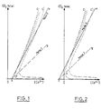
- the figurative point of water passes from M 1 located on the left of curve C to M 2 located slightly to the right of curve C (see Figures 3, 4 , 5 and 6). It first passes from M o to M 1 under the effect of the addition of CO 2 , which is necessary when the mere addition of Ca (OH) 2 does not allow the treated water to be represented above of the half-line SX, slope 2 (see Figures 5 and 6).
- water utilities generally prefer to use reagents other than lime to make the water aggressive in encrusting with solid CaC0 3 which they have.
- reagents other than lime For example, they use the soda which is commercially available in the form of a solution and which is therefore more convenient to use than lime.
- M 1 be the figurative point of the aggressive water to be treated (see Figure 7). This point is not modified by the addition of sodium hydroxide while the calcocarbonic equilibrium curve is shifted to the left and at the same time more or less distorted. The treated water is therefore likely to be encrusting, which is the case seen in the figure.
- the object of the present invention is to remedy the drawbacks of known methods by providing a method which provides effective protection for water transport pipes and the implementation of which is much less expensive than that of known methods.
- the invention relates to a method for protecting against corrosion the interior walls of ferrous or cement-based metals of water pipes, in which water is continuously withdrawn from the pipe, water which is passed through a saturator upstream of which solid lime is added, after which the water is reintroduced into the pipeline, the quantity of lime added to the water in the pipeline being such that the figurative point of the water after treatment, in a diagram where the concentration of total C0 2 is on the ordinate and the concentration of Ca2 + is on the abscissa, is located in a zone between the curve of calcocarbonic equilibrium and the curve of spontaneous precipitation of CaC0 3 and above the half-line SX with a slope equal to 2, S being located on the abscissa axis and its abscissa being a function of the concentration of SO ions , CI - , NO , M g 2+ , Na + and K + .
- this process is characterized in that before being introduced into the saturator, the water withdrawn is mixed in a decarbonator with a solution devoid of total C0 2 and charged with lime coming from the saturator, the flow rate of the solution going from the saturator to the decarbonator being sufficiently high to allow the almost complete elimination of the total C0 2 in the decarbonator by precipitation of CaC0 3 .
- the installation for implementing the method according to the invention comprises a storage tank for powdered lime, a bypass circuit for taking water from a pipe, a lime saturator placed on this bypass circuit, means for introducing powdered lime into the saturator.
- this installation is characterized in that the bypass circuit comprises, upstream of the saturator, relatively to the direction of water circulation, a decarbonator supplied with the water to be treated, in that the pipe which connects the outlet of the saturator to the pipe comprises a bypass to recycle to the decarbonator part of the solution leaving the saturator, and in that the powdered lime is introduced into the pipe which connects the outlet of the decarbonator to the inlet of the saturator.
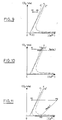
- 3rd case the particles of solid Ca (OH) 2 are introduced into the water at a dose defined by the segment M 1 M 2 , the point M 2 belonging to the domain of unstable waters (FIG. 11).
- the water flow in line 1 would be equal to Q.
- the water flow in bypass 2 where lime Ca (OH) 2 would be added would be equal to q.
- M 1 be the figurative point of aggressive water with respect to solid CaC0 3 , which we have ( Figure 13).
- the particles of solid Ca (OH) 2 would be introduced into this water at a dose defined by the segment M l , M 2 , the point M 2 being located in the domain of encrusting waters, that is to say to the right of the calcocarbonic equilibrium curve (curve C) and to the left of the spontaneous precipitation curve for CaC0 3 (curve C ').
- the coagulant used is not an aluminum salt
- the water remains long enough in such an installation so that solid Ca (OH) 2 can dissolve therein almost completely.
- the water from the clarification installation can therefore have the desirable concentration of Ca2 + ions.
- Such a reagent is commonly obtained by adding Ca (OH) 2 solid in a saturator through which water taken from the water available, according to the diagram in Figure 14.
- the water thus taken stays about one hour in saturator S in contact with particles of solid Ca (OH) 2 (see Figure 15).
- Such a stay promotes the dissolution of these particles, which is hindered, as we recall, by the deposits of CaC0 3 formed around.
- the water introduced into the network is shown in M 4 , slightly to the right of the calcocarbon equilibrium curve (curve C).
- the point M 4 is the barycenter of the point M 1 (mass Q - q) and of the point M 3 (mass q), where Q and q represent respectively the flow introduced into the network and the flow passing through the saturator.
- the disadvantages presented by the use of a lime saturator of the aforementioned type are as follows: Firstly, an incomplete dissolution of solid Ca (OH) 2 is observed.
- the deposits which are extracted from the lime saturator S mainly contain solid CaC0 3 . However, they also contain residual particles of solid Ca (OH) 2 . Although the water remains on the order of one hour in saturator S, the dissolution of these particles is far from complete.
- the rate of dissolution of solid Ca (OH) 2 in fact decreases more and more as the concentration of water in dissolved Ca (OH) 2 increases and approaches the rate of saturation.
- the lime saturator S of the current type has a large volume, resulting from the need for prolonged contact between the water passing through the apparatus and the particles of solid Ca (OH) 2. .
- This volume is calculated according to the numerical example below.
- this water is the mixture of the solution from the saturator, shown in M 3 , and the water that has not passed through the saturator, shown in M 1 ).
- composition of the water introduced into the network 1 varies according to the Ca (OH) 2 saturation rate of the solution from the saturator. This rate is itself variable as indicated above.
- Point M 4 is the barycenter of point M 1 (mass Q - q) and point M 3 (mass q):
- the calculated daily consumption of lime is therefore 0.73 tonnes. But the actual consumption is greater, taking into account the residual particles of solid Ca (OH) 2 that are not dissolved.
- This installation mainly comprises a tank R for lime powder storage, a bypass circuit 2 for taking water from a pipe 1 and a lime saturator S placed on this drainage circuit vation 2.
- a horizontal screw feeder 3 which pours the lime powder into a funnel 4 which communicates with a pipe 5 connected to the outlet of a decarbonator D and to the inlet of the saturator S.
- the bypass circuit 2 comprises, upstream of the saturator S, relative to the direction of water circulation, a decarbonator D supplied with the water to be treated.
- the pipe 6 which connects the outlet of the saturator S to the pipe 1 comprises a bypass 7 for recycling to the decarbonator D part of the solution leaving the saturator S.
- the lower part of the decarbonator D comprises a tube 9 for evacuating the precipitated CaC0 3 .
- the recycling bypass 7 from the saturator S comprises a pump 10 and a valve 11 for adjusting the flow rate.
- the saturator S is provided with an agitator 12 and tranquilization plates 13.
- the water introduced into the installation is first mixed in a decarbonator D with a solution from the saturator S.
- This solution devoid of carbonic elements, has a constant content of Ca (OH) 2 , for example 75% of the concentration corresponding to saturation. It is represented in FIG. 19 at a point such as M 4 , situated to the left of the saturation curve in Ca (OH) 2 (curve C ”) and belonging to the branch of the calcocarbon equilibrium curve (curve C) , which is practically confused with the x-axis.
- the water from decarbonator D is mixed with solid Ca (OH) 2 upstream from saturator S. No precipitate of CaCO 3 can form in the saturator.
- the dissolution of the solid phase which is accelerated by means of an agitator, very quickly leads to the formation of a solution of determined concentration of Ca (OH) 2 .
- the figurative point of water changes from M 3 to M 4 .
- the water introduced into line 1 of the network downstream of the treatment is shown in M 5 , slightly to the right of the calcocarbon equilibrium curve (curve C).
- the point M 5 is the barycenter of the point M 1 (mass Q - q) and of the point M 4 (mass q), where Q and q respectively represent the flow introduced into the pipe 1 of the network and the flow through the installation.
- the main advantage of the installation is that the resulting solution can respond to a defined composition despite the daily variations in the flow of water introduced into the network. It suffices to vary proportionally the flow rate q passing through the installation. As a result, the water introduced into the network can also respond to a defined composition and that the formation of a protective deposit of solid CaC0 3 on the interior walls of the pipes is possible.
- the installation has a reduced volume.
- the volume of the decarbonator D and that of the saturator S are both much lower than the volume of the saturator of the current type.
- the residence time of the water is only of the order of 10 minutes in each compartment of the new installation whereas it is of the order of one hour in the current apparatus.
- the storage capacity is therefore reduced by around two thirds.
- composition of the water introduced into the network (shown in M 5 ) is the same as that calculated previously, which corresponds to the case of the lime saturator of the current type. But in the case of the installation according to the invention, and unlike the case of the current saturator, this composition is stable.
- Q denotes the flow introduced into the network and q denotes the flow introduced into the installation.
- Point M 5 is the barycenter of point M 1 (mass Qq) and point M 4 (mass q):
- the residence time of the water is of the order of 10 minutes in the decarbonator D as in the saturator S.
- the recycling rate r must be slightly higher than the value for which the water coming from the decarbonator would be represented at the top P of the calcocarbonic equilibrium curve (curve C).
Landscapes
- Engineering & Computer Science (AREA)
- General Engineering & Computer Science (AREA)
- Mechanical Engineering (AREA)
- Chemical & Material Sciences (AREA)
- Organic Chemistry (AREA)
- Metallurgy (AREA)
- Materials Engineering (AREA)
- Compounds Of Alkaline-Earth Elements, Aluminum Or Rare-Earth Metals (AREA)
- Preventing Corrosion Or Incrustation Of Metals (AREA)
- Removal Of Specific Substances (AREA)
- Pipeline Systems (AREA)
- Pharmaceuticals Containing Other Organic And Inorganic Compounds (AREA)
- Curing Cements, Concrete, And Artificial Stone (AREA)
- Separation Of Suspended Particles By Flocculating Agents (AREA)
Claims (9)
Priority Applications (1)
| Application Number | Priority Date | Filing Date | Title |
|---|---|---|---|
| AT88905388T ATE72268T1 (de) | 1987-06-12 | 1988-06-09 | Verfahren und einrichtung zum korrosionsschutz von wasserrohrleitungen. |
Applications Claiming Priority (3)
| Application Number | Priority Date | Filing Date | Title |
|---|---|---|---|
| FR8708198 | 1987-06-12 | ||
| FR8708198A FR2616451B1 (fr) | 1987-06-12 | 1987-06-12 | Procede et installation pour proteger les canalisations d'eau contre la corrosion |
| CA000585046A CA1336925C (fr) | 1987-06-12 | 1988-12-06 | Procede et installation pour proteger les canalisations d'eau contre la corrosion |
Publications (2)
| Publication Number | Publication Date |
|---|---|
| EP0328567A1 EP0328567A1 (de) | 1989-08-23 |
| EP0328567B1 true EP0328567B1 (de) | 1992-01-29 |
Family
ID=25672277
Family Applications (1)
| Application Number | Title | Priority Date | Filing Date |
|---|---|---|---|
| EP88905388A Expired - Lifetime EP0328567B1 (de) | 1987-06-12 | 1988-06-09 | Verfahren und einrichtung zum korrosionsschutz von wasserrohrleitungen |
Country Status (7)
| Country | Link |
|---|---|
| US (1) | US5051281A (de) |
| EP (1) | EP0328567B1 (de) |
| AT (1) | ATE72268T1 (de) |
| CA (1) | CA1336925C (de) |
| DE (1) | DE3868260D1 (de) |
| FR (1) | FR2616451B1 (de) |
| WO (1) | WO1988009832A1 (de) |
Families Citing this family (4)
| Publication number | Priority date | Publication date | Assignee | Title |
|---|---|---|---|---|
| JPH0632820B2 (ja) * | 1989-01-24 | 1994-05-02 | 呉羽化学工業株式会社 | 水道水のランゲリア指数の改善方法および装置 |
| JP3105309B2 (ja) * | 1991-10-09 | 2000-10-30 | 呉羽化学工業株式会社 | 水道水の改善方法および装置 |
| US5620744A (en) * | 1996-01-04 | 1997-04-15 | Chemical Lime Company | Method of preventing corrosion in concrete pipe |
| CN101381169B (zh) * | 2008-10-12 | 2010-09-08 | 青岛双瑞防腐防污工程有限公司 | 一种海水淡化一级反渗透水的缓蚀方法 |
Family Cites Families (6)
| Publication number | Priority date | Publication date | Assignee | Title |
|---|---|---|---|---|
| BE552541A (de) * | ||||
| US1683521A (en) * | 1926-05-10 | 1928-09-04 | Bourgognion Julianus Wi Meuser | Process of treating water |
| US3640759A (en) * | 1969-04-29 | 1972-02-08 | Nat Water Main Cleaning Co | Method for lining pipes with calcite |
| IL55280A (en) * | 1978-08-04 | 1981-07-31 | Mekoroth Water Co Ltd | Method for calcite coating the inner surface of pipes |
| FR2446260A1 (fr) * | 1979-01-15 | 1980-08-08 | Degremont | Procede et appareil de traitement d'eaux contenant de la chaux |
| IL73198A (en) * | 1984-10-09 | 1988-01-31 | Technion Res & Dev Foundation | Method for rapid controlled coating of the inner surfaces of pipes with a tenacious calcite lining |
-
1987
- 1987-06-12 FR FR8708198A patent/FR2616451B1/fr not_active Expired
-
1988
- 1988-06-09 US US07/328,194 patent/US5051281A/en not_active Expired - Fee Related
- 1988-06-09 WO PCT/FR1988/000294 patent/WO1988009832A1/fr not_active Ceased
- 1988-06-09 DE DE8888905388T patent/DE3868260D1/de not_active Expired - Lifetime
- 1988-06-09 AT AT88905388T patent/ATE72268T1/de not_active IP Right Cessation
- 1988-06-09 EP EP88905388A patent/EP0328567B1/de not_active Expired - Lifetime
- 1988-12-06 CA CA000585046A patent/CA1336925C/fr not_active Expired - Fee Related
Non-Patent Citations (2)
| Title |
|---|
| Industrial and Engineering Chemistry, vol. 37, no. 9, 13. sept. 1945, American Chemical Society, US, S.T.Powell et al.:"Corrosion prevention by controlled calcium", carbonate Scale" * |
| Intern. Water Supply Assoc. proceedings of the 11th Congress, 13-17.Sept. 1976, Amsterdam, G.Poirier et al.:"Chimie des eaux naturelles considérations particulières sur les caractères d'agressivité" * |
Also Published As
| Publication number | Publication date |
|---|---|
| CA1336925C (fr) | 1995-09-05 |
| FR2616451A1 (fr) | 1988-12-16 |
| EP0328567A1 (de) | 1989-08-23 |
| FR2616451B1 (fr) | 1989-10-13 |
| ATE72268T1 (de) | 1992-02-15 |
| DE3868260D1 (de) | 1992-03-12 |
| WO1988009832A1 (fr) | 1988-12-15 |
| US5051281A (en) | 1991-09-24 |
Similar Documents
| Publication | Publication Date | Title |
|---|---|---|
| EP2382163B1 (de) | Verfahren zur behandlung von wasser durch ballastierte ausflockung und absetzung mit vorkontaktierung des wassers mit einem adsorptionsmittel | |
| CA2616624C (fr) | Procede et installation de traitement d'effluents concentres en azote dans un reacteur biologique sequentiel a cycles fractionnes | |
| EP1940745B1 (de) | Wasserbehandlungsverfahren und -anordnung mit integrierter biologischer behandlung mit fixierten bakterien und flockung/dekantierung | |
| He et al. | Field studies of aluminum release and deposition in drinking water distribution systems | |
| CN107285489A (zh) | 一种脱硫废水预处理的装置及方法 | |
| EP0328567B1 (de) | Verfahren und einrichtung zum korrosionsschutz von wasserrohrleitungen | |
| US4767537A (en) | Dewatering of sludge using nitrate | |
| FR3028850B1 (fr) | Procede et installation de traitement de fluide aqueux contenant du thallium | |
| WO2010081903A1 (fr) | Dispositif d'enrobage avec un materiau polymere floculant a l'etat liquide de grains de ballast utilises pour le traitement de l'eau par floculation lestee, et installation correspondante | |
| CN103739117B (zh) | 一种电镀污水深度治理工艺 | |
| CN217921691U (zh) | 一种集装箱式海水淡化设备 | |
| CN106219827A (zh) | 一种磷矿矿井涌水处理系统及方法 | |
| CN213446565U (zh) | 一种脱硫废水处理系统 | |
| Boardman et al. | Use of UASB technology to treat crab processing wastewaters | |
| CN111792759A (zh) | 一种基于碳源回用的污水污泥调理工艺及系统 | |
| CN105601073A (zh) | 一种含油污泥减量化处理方法 | |
| CN206033444U (zh) | 一种磷矿矿井涌水处理系统 | |
| CN106110717B (zh) | 一种具有调节和杂质沉降浓缩一体的选矿水处理系统 | |
| CN108706785A (zh) | 一种采矿冶炼废水异常水质应急处理装置及方法 | |
| EP2637976B1 (de) | Verfahren zur unterstützung eines emissionsfreien und ablagerungsfreien transports von schwefelwasserstoff in abwassersystemen zu kläranlagen | |
| CN103496808A (zh) | 一种炭黑废水处理方法 | |
| AU2012101548B4 (en) | Water Treatment Apparatus | |
| Lu et al. | Re-Mineralization Using Materials | |
| FR2376678A1 (fr) | Procede et installation pour la concentration des eaux residuaires presentant une teneur en sel elevee | |
| JPS58223481A (ja) | 水道水のpH調整方法 |
Legal Events
| Date | Code | Title | Description |
|---|---|---|---|
| PUAI | Public reference made under article 153(3) epc to a published international application that has entered the european phase |
Free format text: ORIGINAL CODE: 0009012 |
|
| 17P | Request for examination filed |
Effective date: 19890210 |
|
| AK | Designated contracting states |
Kind code of ref document: A1 Designated state(s): AT BE CH DE GB IT LI LU NL SE |
|
| 17Q | First examination report despatched |
Effective date: 19901017 |
|
| GRAA | (expected) grant |
Free format text: ORIGINAL CODE: 0009210 |
|
| AK | Designated contracting states |
Kind code of ref document: B1 Designated state(s): AT BE CH DE GB IT LI LU NL SE |
|
| PG25 | Lapsed in a contracting state [announced via postgrant information from national office to epo] |
Ref country code: NL Effective date: 19920129 Ref country code: AT Effective date: 19920129 Ref country code: SE Effective date: 19920129 |
|
| REF | Corresponds to: |
Ref document number: 72268 Country of ref document: AT Date of ref document: 19920215 Kind code of ref document: T |
|
| GBT | Gb: translation of ep patent filed (gb section 77(6)(a)/1977) | ||
| ITF | It: translation for a ep patent filed | ||
| REF | Corresponds to: |
Ref document number: 3868260 Country of ref document: DE Date of ref document: 19920312 |
|
| NLV1 | Nl: lapsed or annulled due to failure to fulfill the requirements of art. 29p and 29m of the patents act | ||
| PLBE | No opposition filed within time limit |
Free format text: ORIGINAL CODE: 0009261 |
|
| STAA | Information on the status of an ep patent application or granted ep patent |
Free format text: STATUS: NO OPPOSITION FILED WITHIN TIME LIMIT |
|
| 26N | No opposition filed | ||
| EPTA | Lu: last paid annual fee | ||
| PGFP | Annual fee paid to national office [announced via postgrant information from national office to epo] |
Ref country code: CH Payment date: 19980616 Year of fee payment: 11 |
|
| PGFP | Annual fee paid to national office [announced via postgrant information from national office to epo] |
Ref country code: LU Payment date: 19980626 Year of fee payment: 11 |
|
| PGFP | Annual fee paid to national office [announced via postgrant information from national office to epo] |
Ref country code: DE Payment date: 19980827 Year of fee payment: 11 |
|
| PG25 | Lapsed in a contracting state [announced via postgrant information from national office to epo] |
Ref country code: LU Free format text: LAPSE BECAUSE OF NON-PAYMENT OF DUE FEES Effective date: 19990609 |
|
| PG25 | Lapsed in a contracting state [announced via postgrant information from national office to epo] |
Ref country code: LI Free format text: LAPSE BECAUSE OF NON-PAYMENT OF DUE FEES Effective date: 19990630 Ref country code: CH Free format text: LAPSE BECAUSE OF NON-PAYMENT OF DUE FEES Effective date: 19990630 |
|
| REG | Reference to a national code |
Ref country code: CH Ref legal event code: PL |
|
| PG25 | Lapsed in a contracting state [announced via postgrant information from national office to epo] |
Ref country code: DE Free format text: LAPSE BECAUSE OF NON-PAYMENT OF DUE FEES Effective date: 20000503 |
|
| REG | Reference to a national code |
Ref country code: GB Ref legal event code: IF02 |
|
| PG25 | Lapsed in a contracting state [announced via postgrant information from national office to epo] |
Ref country code: IT Free format text: LAPSE BECAUSE OF NON-PAYMENT OF DUE FEES;WARNING: LAPSES OF ITALIAN PATENTS WITH EFFECTIVE DATE BEFORE 2007 MAY HAVE OCCURRED AT ANY TIME BEFORE 2007. THE CORRECT EFFECTIVE DATE MAY BE DIFFERENT FROM THE ONE RECORDED. Effective date: 20050609 |
|
| PGFP | Annual fee paid to national office [announced via postgrant information from national office to epo] |
Ref country code: GB Payment date: 20060607 Year of fee payment: 19 |
|
| PGFP | Annual fee paid to national office [announced via postgrant information from national office to epo] |
Ref country code: BE Payment date: 20060817 Year of fee payment: 19 |
|
| BERE | Be: lapsed |
Owner name: *LEGRAND LUC Effective date: 20070630 Owner name: *LEROY PIERRE Effective date: 20070630 |
|
| GBPC | Gb: european patent ceased through non-payment of renewal fee |
Effective date: 20070609 |
|
| PG25 | Lapsed in a contracting state [announced via postgrant information from national office to epo] |
Ref country code: BE Free format text: LAPSE BECAUSE OF NON-PAYMENT OF DUE FEES Effective date: 20070630 |
|
| PG25 | Lapsed in a contracting state [announced via postgrant information from national office to epo] |
Ref country code: GB Free format text: LAPSE BECAUSE OF NON-PAYMENT OF DUE FEES Effective date: 20070609 |