EP0328563B1 - Cuvette and apparatus for performing biological assays - Google Patents
Cuvette and apparatus for performing biological assays Download PDFInfo
- Publication number
- EP0328563B1 EP0328563B1 EP88904998A EP88904998A EP0328563B1 EP 0328563 B1 EP0328563 B1 EP 0328563B1 EP 88904998 A EP88904998 A EP 88904998A EP 88904998 A EP88904998 A EP 88904998A EP 0328563 B1 EP0328563 B1 EP 0328563B1
- Authority
- EP
- European Patent Office
- Prior art keywords
- cuvette
- light
- detector
- optical element
- spheres
- Prior art date
- Legal status (The legal status is an assumption and is not a legal conclusion. Google has not performed a legal analysis and makes no representation as to the accuracy of the status listed.)
- Expired
Links
- 238000004166 bioassay Methods 0.000 title claims description 12
- 230000003287 optical effect Effects 0.000 claims abstract description 45
- 230000009870 specific binding Effects 0.000 claims abstract description 22
- 238000003556 assay Methods 0.000 claims abstract description 19
- 230000008859 change Effects 0.000 claims abstract description 15
- 238000000034 method Methods 0.000 claims abstract description 13
- 239000011230 binding agent Substances 0.000 claims abstract description 11
- 238000000149 argon plasma sintering Methods 0.000 claims abstract description 10
- 239000000463 material Substances 0.000 claims abstract description 9
- 239000012798 spherical particle Substances 0.000 claims abstract description 4
- 239000003153 chemical reaction reagent Substances 0.000 claims description 23
- 238000002156 mixing Methods 0.000 claims description 8
- 238000012795 verification Methods 0.000 claims description 8
- 238000005286 illumination Methods 0.000 claims description 7
- 238000007689 inspection Methods 0.000 claims description 4
- 238000001514 detection method Methods 0.000 claims description 3
- 239000002245 particle Substances 0.000 claims description 3
- 238000012935 Averaging Methods 0.000 claims description 2
- 239000000126 substance Substances 0.000 claims description 2
- 238000012360 testing method Methods 0.000 abstract description 35
- 239000000523 sample Substances 0.000 description 36
- 239000004816 latex Substances 0.000 description 20
- 229920000126 latex Polymers 0.000 description 20
- 238000006243 chemical reaction Methods 0.000 description 8
- 230000004520 agglutination Effects 0.000 description 6
- 238000005259 measurement Methods 0.000 description 6
- 238000004458 analytical method Methods 0.000 description 3
- 230000027455 binding Effects 0.000 description 3
- 239000003795 chemical substances by application Substances 0.000 description 3
- 230000009471 action Effects 0.000 description 2
- 239000000443 aerosol Substances 0.000 description 2
- 230000004523 agglutinating effect Effects 0.000 description 2
- 239000000427 antigen Substances 0.000 description 2
- 102000036639 antigens Human genes 0.000 description 2
- 108091007433 antigens Proteins 0.000 description 2
- QVGXLLKOCUKJST-UHFFFAOYSA-N atomic oxygen Chemical compound [O] QVGXLLKOCUKJST-UHFFFAOYSA-N 0.000 description 2
- 230000015572 biosynthetic process Effects 0.000 description 2
- 238000013461 design Methods 0.000 description 2
- 238000010586 diagram Methods 0.000 description 2
- 238000010790 dilution Methods 0.000 description 2
- 239000012895 dilution Substances 0.000 description 2
- 238000003780 insertion Methods 0.000 description 2
- 230000037431 insertion Effects 0.000 description 2
- 239000002991 molded plastic Substances 0.000 description 2
- 229910052760 oxygen Inorganic materials 0.000 description 2
- 239000001301 oxygen Substances 0.000 description 2
- 230000035945 sensitivity Effects 0.000 description 2
- 239000000725 suspension Substances 0.000 description 2
- 230000000007 visual effect Effects 0.000 description 2
- 238000009736 wetting Methods 0.000 description 2
- LFQSCWFLJHTTHZ-UHFFFAOYSA-N Ethanol Chemical compound CCO LFQSCWFLJHTTHZ-UHFFFAOYSA-N 0.000 description 1
- XUIMIQQOPSSXEZ-UHFFFAOYSA-N Silicon Chemical compound [Si] XUIMIQQOPSSXEZ-UHFFFAOYSA-N 0.000 description 1
- 238000003149 assay kit Methods 0.000 description 1
- 230000000975 bioactive effect Effects 0.000 description 1
- 239000007853 buffer solution Substances 0.000 description 1
- 238000004140 cleaning Methods 0.000 description 1
- 230000008878 coupling Effects 0.000 description 1
- 238000010168 coupling process Methods 0.000 description 1
- 238000005859 coupling reaction Methods 0.000 description 1
- 238000013480 data collection Methods 0.000 description 1
- 230000000881 depressing effect Effects 0.000 description 1
- 238000009826 distribution Methods 0.000 description 1
- 230000000694 effects Effects 0.000 description 1
- 229920001971 elastomer Polymers 0.000 description 1
- 238000011010 flushing procedure Methods 0.000 description 1
- 238000005187 foaming Methods 0.000 description 1
- 239000011521 glass Substances 0.000 description 1
- 238000003018 immunoassay Methods 0.000 description 1
- 230000006872 improvement Effects 0.000 description 1
- 208000015181 infectious disease Diseases 0.000 description 1
- 238000002347 injection Methods 0.000 description 1
- 239000007924 injection Substances 0.000 description 1
- 239000007788 liquid Substances 0.000 description 1
- 239000004973 liquid crystal related substance Substances 0.000 description 1
- 238000004519 manufacturing process Methods 0.000 description 1
- 230000007246 mechanism Effects 0.000 description 1
- 238000000465 moulding Methods 0.000 description 1
- 239000003921 oil Substances 0.000 description 1
- 238000004806 packaging method and process Methods 0.000 description 1
- 239000013610 patient sample Substances 0.000 description 1
- 238000005375 photometry Methods 0.000 description 1
- 238000001020 plasma etching Methods 0.000 description 1
- 238000003825 pressing Methods 0.000 description 1
- 230000008569 process Effects 0.000 description 1
- 238000012545 processing Methods 0.000 description 1
- 230000005855 radiation Effects 0.000 description 1
- 238000013102 re-test Methods 0.000 description 1
- 230000000284 resting effect Effects 0.000 description 1
- 229910052710 silicon Inorganic materials 0.000 description 1
- 239000010703 silicon Substances 0.000 description 1
- 239000000243 solution Substances 0.000 description 1
- 230000001954 sterilising effect Effects 0.000 description 1
- 238000003860 storage Methods 0.000 description 1
- 238000004381 surface treatment Methods 0.000 description 1
- 238000010998 test method Methods 0.000 description 1
- 230000001960 triggered effect Effects 0.000 description 1
- 238000010200 validation analysis Methods 0.000 description 1
Images


Classifications
-
- G—PHYSICS
- G01—MEASURING; TESTING
- G01N—INVESTIGATING OR ANALYSING MATERIALS BY DETERMINING THEIR CHEMICAL OR PHYSICAL PROPERTIES
- G01N33/00—Investigating or analysing materials by specific methods not covered by groups G01N1/00 - G01N31/00
- G01N33/48—Biological material, e.g. blood, urine; Haemocytometers
- G01N33/50—Chemical analysis of biological material, e.g. blood, urine; Testing involving biospecific ligand binding methods; Immunological testing
- G01N33/53—Immunoassay; Biospecific binding assay; Materials therefor
- G01N33/543—Immunoassay; Biospecific binding assay; Materials therefor with an insoluble carrier for immobilising immunochemicals
- G01N33/54313—Immunoassay; Biospecific binding assay; Materials therefor with an insoluble carrier for immobilising immunochemicals the carrier being characterised by its particulate form
-
- G—PHYSICS
- G01—MEASURING; TESTING
- G01N—INVESTIGATING OR ANALYSING MATERIALS BY DETERMINING THEIR CHEMICAL OR PHYSICAL PROPERTIES
- G01N21/00—Investigating or analysing materials by the use of optical means, i.e. using sub-millimetre waves, infrared, visible or ultraviolet light
- G01N21/17—Systems in which incident light is modified in accordance with the properties of the material investigated
- G01N21/47—Scattering, i.e. diffuse reflection
- G01N21/49—Scattering, i.e. diffuse reflection within a body or fluid
- G01N21/51—Scattering, i.e. diffuse reflection within a body or fluid inside a container, e.g. in an ampoule
-
- G—PHYSICS
- G01—MEASURING; TESTING
- G01N—INVESTIGATING OR ANALYSING MATERIALS BY DETERMINING THEIR CHEMICAL OR PHYSICAL PROPERTIES
- G01N21/00—Investigating or analysing materials by the use of optical means, i.e. using sub-millimetre waves, infrared, visible or ultraviolet light
- G01N21/17—Systems in which incident light is modified in accordance with the properties of the material investigated
- G01N21/47—Scattering, i.e. diffuse reflection
- G01N21/49—Scattering, i.e. diffuse reflection within a body or fluid
- G01N21/51—Scattering, i.e. diffuse reflection within a body or fluid inside a container, e.g. in an ampoule
- G01N2021/513—Cuvettes for scattering measurements
-
- G—PHYSICS
- G01—MEASURING; TESTING
- G01N—INVESTIGATING OR ANALYSING MATERIALS BY DETERMINING THEIR CHEMICAL OR PHYSICAL PROPERTIES
- G01N2201/00—Features of devices classified in G01N21/00
- G01N2201/02—Mechanical
- G01N2201/025—Mechanical control of operations
- G01N2201/0256—Sensor for insertion of sample, cuvette, test strip
Definitions
- This invention relates to biological assays of the type in which a cuvette is filled with a material having a specific binding agent on its surface and whose ability to scatter light changes upon the addition of a sample containing a specific binding partner to the surface bound agent.
- the invention also relates to apparatus by which such assays may be performed, and in particular relates to a device and technique for verifying whether a particular cuvette is appropriate for use in a particular analysing apparatus.
- Latex agglutination is a well known and established immuno-assay test.
- the basis for the technique lies in the ability to coat latex spheres (300-800nm in diameter) with a specific antibody. If the spheres are exposed to a sample containing the relevant antigen then bonding can occur leading to clumping of the latex balls.
- An alternative form of the test uses latex spheres coated in antigen, samples can then be tested for the presence of the relevant antibody.
- test has been carried out manually by transferring quantities of control and test latex from phials within a reagent kit, to a piece of black card, and mixed with the sample to be tested. Agglutination of the latex balls can be clearly seen against the dark background.
- the change in light scattering properties is brought about by the increased diameter of the spheres due to the binding of the sample material thereto, and if there is binding, then the sample is assumed to contain the specific binding partner of the material on the spheres.
- US patent no. 4,452,902 describes apparatus for measuring generally the properties of a liquid contained in a vessel, in which the vessel is rotated in a centrifuge so as to lie in a horizontal resting position and in which a source of radiation is directed through the vessel to a detector when the vessel is in a particular position, relative to the source and detector, during its rotation.
- a cuvette adapted to contain spherical particles having a specific binding agent on the surface thereof and which have a detectably different light scattering characteristic in the presence of a material having a specific binding partner therefor, the cuvette including a window through which light can be projected for the purpose of determining any change in light scattering properties of the contents of the cuvette, characterised by an optical element which, when light passes therethrough, causes at least some of the light to be deflected off axis towards a particular point.
- a cuvette By using such a cuvette in combination with a light level detector located at said particular point, a cuvette can be validated before an assay is performed by checking the light level at the said particular point.
- the point is fixed in space and it is merely necessary to check the light level at the said point and determine whether light is incident thereat.
- the point can lie at any position around a circular path and either the light detector must be movable around the path to find the particular point, or the cuvette must be rotated to move the point onto the detector.
- the cuvette contains small latex spheres which are coated with the specific binding agent and the reagent sample is checked by determining whether there is any change in the pattern of the light scattered from the spheres after the sample reagent has been added. (It is understood that the change in scattered light is brought about by the clumping together of the spheres due to agglutination when the specific binding partner is present in the sample reagent).
- the optical element may be in the form of a hologram or a diffraction grating or a lens, in or on a wall of the cuvette, or any combination thereof.
- the light sensitive detector may comprise a photocell.
- Circuit means may be provided, responsive to the detector output, to provide an electrical pulse when light, focussed, or diffracted, or otherwise diverted by the optical element, is incident thereon.
- the cuvette is rotatable about its axis and the optical element acts so as to focus or diffract or otherwise divert light parallel to the axis, through the said off-axis point, which as the cuvette is rotated, therefore describes a circular path centered on the axis of the cuvette, and the detector is located at one point around this circular path, and the cuvette is rotated through 360° to produce an electrical pulse in the output of the detector as the diverted light passes through the said point.
- a method of checking whether a cuvette has a specific optical element includes the steps of illuminating the cuvette and effecting relative rotation between the cuvette and a detector; and is characterised by the step of investigating whether or not the detector generates a particular electrical signal during the rotation, caused by light reflected or refracted or otherwise diverted by the optical element being incident on the detector.
- an inhibit signal may be generated preventing further use of the cuvette.
- apparatus for performing a biological assay on the contents of a cuvette which contains a plurality of spheres having a specific binding agent on the surface thereof and to which a sample reagent is to be added which may or may not contain a specific binding partner to the material on the spheres (the presence of a specific binding partner being detected by a change in the light scatter pattern from the spheres, in the presence of appropriate illumination), the apparatus including illumination means for automatically illuminating the cuvette and detector means for determining the light scatter pattern before and after the sample reagent has been added, characterised by verification means for checking whether the cuvette has an appropriate optical element, the verification means comprising: means for moving the illumination means in a predictable manner during at least a preliminary movement of the cuvette; a light sensitive detector for checking for the presenceof light at a point along a path along which light will be diverted if the cuvette includes the appropriate optical element; and circuit means responsive to electrical signals from the light sensitive detector which normally inhibits the operation of the apparatus to
- the apparatus may include automated sample reagent addition means which likewise may be inhibited until the apparatus has checked that the cuvette incorporates the appropriate optical element.
- sample reagent may be added to the cuvette before insertion into the apparatus and the assay is performed after satisfactory verification.
- the mixing of the sample and the coated spheres may be performed by shaking the cuvette before insertion and/or automatically upon rotation of the cuvette during the preliminary rotation.
- the optically based assay may be performed before or during or after the said rotation and only completed (or released as a test result) if an enabling signal is generated during the said rotation.
- the optical path within the apparatus may include lenses which co-operate, in the presence of the appropriate optical element if present in the cuvette, to focus light diverted by the optical element, onto the light sensitive detector.
- the cuvette is adapted to be rotated about a central axis and drive means is provided within the apparatus for effecting the rotation.
- the verifying step involves a controlled rotation of the cuvette through 360° and the circuit means is rendered sensitive to the output of the light detector to determine any increase in light incident thereon during the controlled rotation of the cuvette.
- the apparatus may be further characterised by: a plurality of light sensitive detectors mounted to the rear of the cuvette, and means for illuminating the cuvette so as to produce a light scatter pattern for detection by the plurality of detectors.
- the detectors may be spaced apart in a fixed manner to form an array and the array may be movable so that the actual shape of the light scatter pattern may be determined by, for example, averaging signals obtained from the spaced detectors as they are moved in a predictable and controlled manner relative to the light scatter pattern.
- an analyser for use with a cuvette, which cuvette includes an optical element as at least part of one of its walls to divert light incident thereon off-axis in a particular direction, and by which biological assays can be performed by investigating the change in light scatter from coated spheres within the cuvette due to chemical bonding within the cuvette, the analyser comprising first light detector means from which electrical signals can be obtained for determining changes in the pattern of the light scattered by particles contained within the cuvette, due to the addition of a sample reagent thereto, the analyser being characterised by :-
- the first light detector means may comprise a pair of detectors, spaced apart, which are movable relative to the cuvette (or the cuvette is moveable relative to the detectors) to provide two electrical signals which can be combined to enable the slope of the light scatter pattern to be derived by computing the mean value of the two signals so obtained.
- Validation of a cuvette may be performed by positioning the cuvette so that light incident on the optical element (if present) will be diverted onto the second off-axis light detector means.
- a method of performing a biological assay comprising the steps of inserting a cuvette into an analyser and shining light through the cuvette; characterised by the steps of:
- the optical element may comprise a holographic lens having a refractive property similar to that of a convex lens.
- the light employed to illuminate the cuvette is preferably collimated or at least has well defined convergence.
- the detector for detecting the light scatter may be a large area array photodetector or an array of individual photodetectors or a television camera.
- the invention may be employed to inhibit the use of cuvettes from an unauthorised source with a particular analyser by arranging that if verification is not obtained, the analyser rejects the cuvette and/or terminates or inhibits the detection steps of the assay forthwith, or simply fails to record the result of the assay.
- the cuvette may be a two chamber cuvette containing test and control latex in the two separate chambers. To use such an instrument the operator will first add the sample material to the cuvette containing both test and control latex. The cuvette will then be placed in the instrument which will monitor the rate of agglutination of the particles in the two chambers by measuring the intensity of scattered light as a function of time.
- the instrument may be a small desk top unit providing an indication of pass/fail or "test again” or in uncertain tests an indication to "dilute the sample”. Power to the instrument is typically supplied from internal cells which can be recharged from a standard charging unit.
- the cuvette may include a base and a cap which latter contains two ski-slope pockets which contain the dried latex and which prevent its wetting until the cuvette is inverted.
- the chamber shape and size can help control the size of the mixing bubble and allow it to move smoothly around the chamber.
- a location feature is provided to control the relative orientation of cap and base +/-6°, allowing a minimum vent area of 0.2mm2 during closure of the cuvette. This prevents aerosol formation and is closed once assembly of the cap and base has been completed.
- Visual guide features may be added to the location feature, to make it easier to orientate by eye.
- the optical element is a grating this can provide the off-axis verification illumination and the timing signal for optical inspection of the reaction.
- two gratings are provided 4mm in diameter and positioned on the external face, concentrically with two 4mm diameter viewing windows.
- the gratings may be orientated radialy on the side of the chamber containing the control latex and tangentially on the side containing the test latex in the reaction chamber, thus allowing the instrument to distinguish between light from the control and reaction chambers.
- the exact positioning of the gratings relative to the reagent chambers is a matter of choice.
- the gratings may superimpose the viewing windows and the instrument measures the state of the reaction through the viewing windows and the gratings.
- the gratings may be positioned over the regions between the chambers so that the state of reaction can be viewed uninterruptedly through the windows.
- a time delay may be introduced into the operation of the instrument to permit inspection of the reaction after the passage of the grating. It should be noted that this should reduce somewhat the instrument tolerance of errors in cuvette filling or of sample foaming.
- the gratings typically have a nominal groove spacing of 2.33u which produce a deflection angle of 25°.
- the optimum 0.25u nominal grating depth gives a nominal design diffraction efficiency for the grating of 14% at 940mm.
- bubble mobility cuvettes may be plasma etched in batches, and may be treated with oxygen plasma for a period of time (typically 3 minutes) per batch.
- the cuvettes are preferably dipped for 30 seconds in a 0.05% Calsoline oil (HS) solution, spun dry and then vacuum dried.
- HS Calsoline oil
- the caps may be orientated using a bowl feeder before the control and reagent latexes are deposited into the latex chambers and dried.
- An asymetric feature may be added to the rim of the cap to assist in orientation for this production operation.
- Caps and bases may be packed in vacuum formed trays to maintain appropriate humidity levels in storage and to form a secondary spillage tray for the user when assembling the cuvettes.
- the invention envisages that a user will probably purchase the cuvettes in the form of a kit of, say, 20 tests.
- Each kit might contain a number of individually packed cuvettes, an instruction leaflet, buffer solution (if appropriate) and perhaps a patient record card.
- a typical test procedure might be as follows:
- collimated light 10 from a source 12 is directed towards one face 14 of a cuvette generally designated 16.
- the face 14 includes thereon a grating or a light transmitting hologram having a refractive property similar to a convex lens, as denoted at 18, and contains spherical particles in suspension each of which is coated with a specific binding agent.
- a large area photodetector or array of photodetectors or television camera or the like is located at 20 and the light scatter pattern is determined by interrogating the detectors or scanning the television camera target and the signal analysed.
- the circuit means for achieving the analysis is shown at 22.
- a lens 24 located to the rear of the cuvette 16 focusses any light which has been transmitted through the cuvette without being scattered, to a point at 26 at which it can be conveyed away or blocked so that it forms no part of the image on the detector 20. Light which has been scattered from one of more of the spheres will be collected by the lens 24 and the light scatter pattern is formed on the large area detector.
- the function of the lens 18 on the front wall 14 of the cuvette 16 is to divert some of the light incident on the cuvette to an off-axis point 28 at which a second photocell 30 is located.
- the electrical signals (if any) from the photocell 30 are supplied to a detector circuit 32 which normally transmits an inhibit signal to the remainder of the apparatus but in the presence of an electrical signal indicating that light has been received by the photocell 30 the circuit means 32 generates an enable signal to thereby enable the remainder of the apparatus to perform an assay.
- inhibit signal and enable signals are applied to the circuit means 22.
- the cuvette 16 is mounted so as to be rotated by an electric motor 34 through the intermediatry of a rubber drive wheel 35. Drive for the motor is effected automatically from operation of the start button switch 38 associated with control circit 36. Appropriate interlocks and proximity switching means is provided so that circuit 36 is only enabled after a cuvette has been satisfactorily positioned within the holder (not shown). Thereafter depressing button switch 38 will cause the motor 34 to rotate and thereby rotate the holder (not shown) through 360°. Simultaneously the control circuit 36 provides power to the light source 12 and further enables the circuit 32 for the duration of the 360° rotation.
- the holographic lens 18 will produce a spot of light which will intercept the detector 30 at some point during the rotation of the cuvette and produce a signal in the output of the detector 30 which will remove the inhibit signal in the output circuit means 32 and replace it with an enable signal. The latter then enables circuit 22.(and if
- the enabling signal man also enable visible or audible indicator means to indicate to the user that the sample reagent can now be added to the cuvette.
- the addition may be by means of a hypodermic syringe.
- the sample addition may be automatic, from a reservoir or injector associated with the apparatus (not shown), or may occur as a result of shaking or rotating the cuvette.
- two detectors may be located in a plane perpendicular to the axis 40. Two such detectors are shown at 42 and 44. By moving the two detectors 42 and 44 along the axis 40 towards and away from the cuvette, so the light scatter pattern intensity can be determined by summing the outputs from the two detectors 42 and 44.
- the cuvette 48 shown in Figures 2 to 5 is a two chamber device containing test latex in one chamber 50 and control latex in a separate chamber 52.
- the cuvette includes a base 54 and a cap 56.
- the cap contains two ski-slope pockets (one of which is shown at 58) which contain the dried latex and which prevent its wetting until the cuvette is inverted.
- the chamber shape and size can help control the size of the mixing bubble and allow it to move smoothly around the chamber.
- a drainage groove is provided at 59.
- a location feature 60 is provided on the cap and a similar feature 62 is provided on the base to control the relative orientation of cap and base +/-6°. This allows a minimum vent area of 0.2mm2 during closure of the cuvette. This prevents aerosol formation and the vent is closed once assembly of the cap and base has been completed.
- Visual guide features may be added to the location feature, to make it easier to orientate by eye.
- Two 4mm diameter gratings are provided at 64 and 66 and positioned on the external face, concentrically with two 4mm diameter viewing windows, one of which is shown at 68.
- the grating over the 'control' chamber 52 is orientated radially whilst that over the "reaction” chamber 50 is orientated tangentially, thus allowing the instrument to distinguish between light from the "control" and “reaction” chambers.
- the gratings typically have a nominal groove spacing of 2.33u which produce a deflection angle of 25°.
- the optimum 0.25u nominal grating depth gives a nominal design diffraction efficiency for the grating of 14% at 940mm.
- bubble mobility cuvettes may be plasma etched in batches, and may be treated with oxygen plasma for a period of time (typically 3 minutes) per batch.
- the instrument is a small desk-top unit formed from a two-part moulding 72, 74.
- An opening with a light tight lid 76 accepts cuvettes for analysis.
- a liquid crystal display unit 78 is used to convey information to the operator, such as; pass/fail/test again/dilute/battery low, cuvette jammed, etc.
- Three buttons 80, 82, 84 placed immediately below the display are used to control operation of the instrument.
- the unit is powered from internal cells 70 recharged from an external low voltage transformer.
- buttons 80 82, 84 arranged under the display allow selection of algorithm and control the operation of the instrument.
- buttons 80 applies power to the unit. It is a toggle action switch, ie. push on and push off. This button is also used to abort a test.
- Button 82 is used to scroll the algorithm number in the display. The selected algorithm will then be used to test data from the cuvette for pass/fail.
- Button 84 is a down scroll button and is used in the same way as the button 82, to reduce the algorithm number.
- the unit is turned on by pushing on/off switch 80.
- the display will show the following:
- the instrument uses optical diffraction to measure the rate of agglutination.
- a collimated beam of light falling on the latex spheres in suspension in the cuvette will cause some of the light to be diffracted from the main collimated beam.
- the effective sphere diameter increases, causing the angular distribution and the intensity of scattered light to be reduced.
- Circuits within the test instrument compare the rate of change of the scattered light from the test chamber and the control chamber to provide the assessment.
- a simple silicon photodiode is mounted on a p.c.b. 90 and is used to monitor the intensity of scattered light.
- This phototide is placed at 3.5mm from the optical axis of the system. This has been shown to provide the optimum, sensitivity.
- the detector used is a 1mm2 detector.
- the grating detectors are similar photodivides placed approximately 11mm from the optical axis. These detectors are designed to sense the diffracted portion of the collimated beam from the gratings. Two detectors are used, one at top-dead centre and the other at 90°. One detector is triggered by the grating for the test chamber, and the other by the grating for the control chamber.
- a collimating lens and an aperture is used to provide a collimated beam from the LED source to interrogate the cuvette.
- a second lens is used to collect the scattered light.
- the two lenses are 25mm focal length and are of moulded plastic. The effect of the focussing lens on the diffracted beam from the grating is to create a spot 2.5 x 1mm at the grating detector plane.
- the cuvette has to be rotated within the instrument to allow mixing of the sample and latex material.
- a single optical system can be used to examine both test and control chambers.
- a six volt DC motor 88 and gear box 92 provides the necessary rotational drive.
- a magnetic coupling (not shown) is used to transmit the drive to the drive wheel within the rotation assembly which can be removed for ease of cleaning in the event of spillage of bioactive materials.
- the rotation rate of the cuvette is of the order of 15 rpm.
- a test is initiated by closing the lid 76 at which point LED, drivers 106 are switched on.
- Current requirements of LED are relatively high, and power can be conserved by only turning the LEDs on during measurements.
- the drivers 106 operate so as to provide constant current to the LEDs to ensure constant light output.
- the outputs from the grating photodiodes 102, 104 are buffered and compare with a threshold voltage in selector 108 to provide a clock signal to the processing unit 94.
- the presence of the clock signal indicates that the appropriate chamber is in the optical beam and that a reading from the signal diode will be valid.
- the signals are amplified by amplifier 110 and the amplified signals are digitised by A/D converter 112 and presented to the processor unit 94 for analysis.
- a display driver 114 controls the display of digits in the display unit 78, so as to provide information to the operator on the instrument status and battery condition as well as the algorithm selected and the test result.
- the motor 80 is only activated when a test is in progress so as to conserve battery life, and a constant current for the motor is obtained from drives 106 and PWR amplifier 116 to maintain a constant motor speed.
- the batteries are charged by an external low voltage charging unit (not shown).
- an RS 232 interface is provided.
- the data to be transmitted through the RS 232 link may contain information on the time that a sample was measured, and the voltage level of that sample.
- the casing parts 72, 74 may be from injection moulded plastics.
- the lid 76 must be light tight.
- the space occupied by the cuvette and magnetically coupled drive wheel must be capable of being cleaned by flushing with alcohol or other sterilising agents.
- a feature of the lid mechanism is that it is preferred that when then lid is opened the cuvette will be ejected into an exit channel. This will allow the next cuvette to be loaded before final removal of the last cuvette.
- Reagent types which can be used with the instrument can be found in the Orion Diagnostica's range of reagent kits, ie Rotalex, Adenalex, Hemolex, Rubalex, Respiralex and Myolex.
- a number of algorithms sufficient to satisfy Orion Diagnostica's range of test kits are stored in a PROM section of the processor 94.
Landscapes
- Health & Medical Sciences (AREA)
- Immunology (AREA)
- Life Sciences & Earth Sciences (AREA)
- Chemical & Material Sciences (AREA)
- Engineering & Computer Science (AREA)
- Physics & Mathematics (AREA)
- Analytical Chemistry (AREA)
- Hematology (AREA)
- Pathology (AREA)
- Molecular Biology (AREA)
- Urology & Nephrology (AREA)
- General Physics & Mathematics (AREA)
- General Health & Medical Sciences (AREA)
- Biochemistry (AREA)
- Biomedical Technology (AREA)
- Food Science & Technology (AREA)
- Medicinal Chemistry (AREA)
- Cell Biology (AREA)
- Biotechnology (AREA)
- Microbiology (AREA)
- Investigating Or Analysing Materials By Optical Means (AREA)
- Investigating Or Analysing Biological Materials (AREA)
- Optical Measuring Cells (AREA)
- Orthopedics, Nursing, And Contraception (AREA)
- Automatic Analysis And Handling Materials Therefor (AREA)
- Measurement Of Radiation (AREA)
- Measuring Or Testing Involving Enzymes Or Micro-Organisms (AREA)
- Measurement And Recording Of Electrical Phenomena And Electrical Characteristics Of The Living Body (AREA)
- Lubricants (AREA)
- Cereal-Derived Products (AREA)
Abstract
Description
- This invention relates to biological assays of the type in which a cuvette is filled with a material having a specific binding agent on its surface and whose ability to scatter light changes upon the addition of a sample containing a specific binding partner to the surface bound agent. The invention also relates to apparatus by which such assays may be performed, and in particular relates to a device and technique for verifying whether a particular cuvette is appropriate for use in a particular analysing apparatus.
- Latex agglutination is a well known and established immuno-assay test. The basis for the technique lies in the ability to coat latex spheres (300-800nm in diameter) with a specific antibody. If the spheres are exposed to a sample containing the relevant antigen then bonding can occur leading to clumping of the latex balls. An alternative form of the test uses latex spheres coated in antigen, samples can then be tested for the presence of the relevant antibody.
- Traditionally the test has been carried out manually by transferring quantities of control and test latex from phials within a reagent kit, to a piece of black card, and mixed with the sample to be tested. Agglutination of the latex balls can be clearly seen against the dark background.
- It is also known to perform a biological assay by filling a cuvette with a plurality of small diameter spheres (typically of latex) coated with a specific binding agent and to add a sample material to the cuvette and observe whether there is any change in the light scattering properties of the contents of the cuvette as a result of any binding of the sample to the spheres. The change in light scattering properties is brought about by the increased diameter of the spheres due to the binding of the sample material thereto, and if there is binding, then the sample is assumed to contain the specific binding partner of the material on the spheres.
- US patent no. 4,372,683 describes photometric analysis apparatus which could be used to perform such an assay, in which a cylindrical glass sample container (analogous to a cuvette) can be rotated about its cylindrical axis whilst optical measurements are carried out on a sample in the container. This rotation compensates for optical variations and imperfections in the container wall and hence removes the sensitivity of any measured optical signal to the rotational orientation of the container.
- US patent no. 4,452,902 describes apparatus for measuring generally the properties of a liquid contained in a vessel, in which the vessel is rotated in a centrifuge so as to lie in a horizontal resting position and in which a source of radiation is directed through the vessel to a detector when the vessel is in a particular position, relative to the source and detector, during its rotation.
- In both of the above documents, the apparatus described and its method of use involve the use of conventional sample containers which are not adapted in any particular way to interact with the apparatus.
- It is one object of the present invention to provide an improved cuvette by which such a biological assay as is described above can be performed.
- It is another object of the present invention to provide an improved analyser for performing assays using such cuvettes and which performs a verifying test on a cuvette before a biological assay is performed.
- It is a further object of the invention to provide an improved method of performing a biological assay.
- According to one aspect of the invention there is provided a cuvette adapted to contain spherical particles having a specific binding agent on the surface thereof and which have a detectably different light scattering characteristic in the presence of a material having a specific binding partner therefor, the cuvette including a window through which light can be projected for the purpose of determining any change in light scattering properties of the contents of the cuvette, characterised by an optical element which, when light passes therethrough, causes at least some of the light to be deflected off axis towards a particular point.
- By using such a cuvette in combination with a light level detector located at said particular point, a cuvette can be validated before an assay is performed by checking the light level at the said particular point.
- Where the cuvette can only be inserted into a testing apparatus in one way, the point is fixed in space and it is merely necessary to check the light level at the said point and determine whether light is incident thereat.
- If the cuvette is rotatable about its axis, the point can lie at any position around a circular path and either the light detector must be movable around the path to find the particular point, or the cuvette must be rotated to move the point onto the detector.
- In manner known per se the cuvette contains small latex spheres which are coated with the specific binding agent and the reagent sample is checked by determining whether there is any change in the pattern of the light scattered from the spheres after the sample reagent has been added. (It is understood that the change in scattered light is brought about by the clumping together of the spheres due to agglutination when the specific binding partner is present in the sample reagent).
- The optical element may be in the form of a hologram or a diffraction grating or a lens, in or on a wall of the cuvette, or any combination thereof.
- The light sensitive detector may comprise a photocell.
- Circuit means may be provided, responsive to the detector output, to provide an electrical pulse when light, focussed, or diffracted, or otherwise diverted by the optical element, is incident thereon.
- Conveniently, the cuvette is rotatable about its axis and the optical element acts so as to focus or diffract or otherwise divert light parallel to the axis, through the said off-axis point, which as the cuvette is rotated, therefore describes a circular path centered on the axis of the cuvette, and the detector is located at one point around this circular path, and the cuvette is rotated through 360° to produce an electrical pulse in the output of the detector as the diverted light passes through the said point.
- Since the cuvette should only produce a single electrical pulse during a 360° rotation, further circuit means may be provided to determine the number of pulses detected, so that a cuvette can be identified reliably and is only indicated as acceptable if only the one pulse is detected during the rotation.
- According therefore to another aspect of the invention a method of checking whether a cuvette has a specific optical element includes the steps of illuminating the cuvette and effecting relative rotation between the cuvette and a detector; and is characterised by the step of investigating whether or not the detector generates a particular electrical signal during the rotation, caused by light reflected or refracted or otherwise diverted by the optical element being incident on the detector.
- If no such signal is detected, an inhibit signal may be generated preventing further use of the cuvette.
- According to another aspect of the present invention, there is provided apparatus for performing a biological assay on the contents of a cuvette which contains a plurality of spheres having a specific binding agent on the surface thereof and to which a sample reagent is to be added which may or may not contain a specific binding partner to the material on the spheres (the presence of a specific binding partner being detected by a change in the light scatter pattern from the spheres, in the presence of appropriate illumination), the apparatus including illumination means for automatically illuminating the cuvette and detector means for determining the light scatter pattern before and after the sample reagent has been added, characterised by verification means for checking whether the cuvette has an appropriate optical element, the verification means comprising:
means for moving the illumination means in a predictable manner during at least a preliminary movement of the cuvette;
a light sensitive detector for checking for the presenceof light at a point along a path along which light will be diverted if the cuvette includes the appropriate optical element; and
circuit means responsive to electrical signals from the light sensitive detector which normally inhibits the operation of the apparatus to perform the said assay (or at least inhibits the inspection of the change in light scattering properties of the cuvette contents), but which generates an enabling signal to permit the apparatus to perform the assay if an appropriate signal is generated by the detector during the said preliminary movement of the cuvette, the appropriate signal being generated if the detector detects the presence of light. - The apparatus may include automated sample reagent addition means which likewise may be inhibited until the apparatus has checked that the cuvette incorporates the appropriate optical element.
- Alternatively the sample reagent may be added to the cuvette before insertion into the apparatus and the assay is performed after satisfactory verification.
- Alternatively the mixing of the sample and the coated spheres may be performed by shaking the cuvette before insertion and/or automatically upon rotation of the cuvette during the preliminary rotation.
- The optically based assay may be performed before or during or after the said rotation and only completed (or released as a test result) if an enabling signal is generated during the said rotation.
- The optical path within the apparatus may include lenses which co-operate, in the presence of the appropriate optical element if present in the cuvette, to focus light diverted by the optical element, onto the light sensitive detector.
- Preferably the cuvette is adapted to be rotated about a central axis and drive means is provided within the apparatus for effecting the rotation.
- Preferably the verifying step involves a controlled rotation of the cuvette through 360° and the circuit means is rendered sensitive to the output of the light detector to determine any increase in light incident thereon during the controlled rotation of the cuvette.
- Since a cuvette which is not validated cannot be used, it is not essential that the verification step is performed before the sample reagent has been mixed with the coated spheres.
- The apparatus may be further characterised by:
a plurality of light sensitive detectors mounted to the rear of the cuvette, and
means for illuminating the cuvette so as to produce a light scatter pattern for detection by the plurality of detectors. - The detectors may be spaced apart in a fixed manner to form an array and the array may be movable so that the actual shape of the light scatter pattern may be determined by, for example, averaging signals obtained from the spaced detectors as they are moved in a predictable and controlled manner relative to the light scatter pattern.
- According to another aspect of the invention, there is provided an analyser for use with a cuvette, which cuvette includes an optical element as at least part of one of its walls to divert light incident thereon off-axis in a particular direction, and by which biological assays can be performed by investigating the change in light scatter from coated spheres within the cuvette due to chemical bonding within the cuvette, the analyser comprising first light detector means from which electrical signals can be obtained for determining changes in the pattern of the light scattered by particles contained within the cuvette, due to the addition of a sample reagent thereto, the analyser being characterised by:-
- (a) a source of light for projecting light onto a wall of the cuvette having the optical element formed therein; and
- (b) second light detector means, radially displaced from the axis of the cuvette, for receiving light diverted by the optical element of the cuvette.
- The first light detector means may comprise a pair of detectors, spaced apart, which are movable relative to the cuvette (or the cuvette is moveable relative to the detectors) to provide two electrical signals which can be combined to enable the slope of the light scatter pattern to be derived by computing the mean value of the two signals so obtained.
- Validation of a cuvette may be performed by positioning the cuvette so that light incident on the optical element (if present) will be diverted onto the second off-axis light detector means.
- According to another aspect of the invention there is provided a method of performing a biological assay comprising the steps of inserting a cuvette into an analyser and shining light through the cuvette;
characterised by the steps of: - (a) rotating the cuvette relative to a light detector situated on a circular path which the light will describe as the cuvette is rotated if an appropriate optical element is incorporated in the cuvette to divert the light shone through the cuvette;
- (b) generating an electrical signal if light falls on the detector during the said rotation;
- (c) determining if a single electrical signal appears in the output of the detector during the rotation of the cuvette, thereby to generate an enabling signal;
- (d) causing a mixing in the cuvette of a sample reagent and a plurality of spheres having a specific binding agent on the surface thereof; and
- (e) performing the assay by comparing light scattered by the spheres before and after mixing, only if an enabling signal is generated.
- The optical element may comprise a holographic lens having a refractive property similar to that of a convex lens.
- The light employed to illuminate the cuvette is preferably collimated or at least has well defined convergence.
- The detector for detecting the light scatter may be a large area array photodetector or an array of individual photodetectors or a television camera.
- The invention may be employed to inhibit the use of cuvettes from an unauthorised source with a particular analyser by arranging that if verification is not obtained, the analyser rejects the cuvette and/or terminates or inhibits the detection steps of the assay forthwith, or simply fails to record the result of the assay.
- The cuvette may be a two chamber cuvette containing test and control latex in the two separate chambers. To use such an instrument the operator will first add the sample material to the cuvette containing both test and control latex. The cuvette will then be placed in the instrument which will monitor the rate of agglutination of the particles in the two chambers by measuring the intensity of scattered light as a function of time. The instrument may be a small desk top unit providing an indication of pass/fail or "test again" or in uncertain tests an indication to "dilute the sample". Power to the instrument is typically supplied from internal cells which can be recharged from a standard charging unit.
- The cuvette may include a base and a cap which latter contains two ski-slope pockets which contain the dried latex and which prevent its wetting until the cuvette is inverted. The chamber shape and size can help control the size of the mixing bubble and allow it to move smoothly around the chamber.
- Preferably a location feature is provided to control the relative orientation of cap and base +/-6°, allowing a minimum vent area of 0.2mm² during closure of the cuvette. This prevents aerosol formation and is closed once assembly of the cap and base has been completed.
- Visual guide features may be added to the location feature, to make it easier to orientate by eye.
- Where the optical element is a grating this can provide the off-axis verification illumination and the timing signal for optical inspection of the reaction. Typically two gratings are provided 4mm in diameter and positioned on the external face, concentrically with two 4mm diameter viewing windows. The gratings may be orientated radialy on the side of the chamber containing the control latex and tangentially on the side containing the test latex in the reaction chamber, thus allowing the instrument to distinguish between light from the control and reaction chambers.
- The exact positioning of the gratings relative to the reagent chambers is a matter of choice. Thus in one type of cuvette the gratings may superimpose the viewing windows and the instrument measures the state of the reaction through the viewing windows and the gratings. In another type of cuvette the gratings may be positioned over the regions between the chambers so that the state of reaction can be viewed uninterruptedly through the windows.
- A time delay may be introduced into the operation of the instrument to permit inspection of the reaction after the passage of the grating. It should be noted that this should reduce somewhat the instrument tolerance of errors in cuvette filling or of sample foaming.
- The gratings typically have a nominal groove spacing of 2.33u which produce a deflection angle of 25°. The optimum 0.25u nominal grating depth gives a nominal design diffraction efficiency for the grating of 14% at 940mm.
- There may be loss of diffraction efficiency with moulded gratings but diffraction efficiencies of greater then approximately 5% have been found to give acceptable grating signals from an agglutinating sample in the instrument.
- To achieve acceptable bubble mobility cuvettes may be plasma etched in batches, and may be treated with oxygen plasma for a period of time (typically 3 minutes) per batch.
- Within 2 days of this treatment the cuvettes are preferably dipped for 30 seconds in a 0.05% Calsoline oil (HS) solution, spun dry and then vacuum dried. As plasma etching does not in general produce a permanent improvement in wettability this secondary process may be necessary to preserve the plasma etched wettability.
- Following surface treatment of the cuvettes, the caps may be orientated using a bowl feeder before the control and reagent latexes are deposited into the latex chambers and dried. An asymetric feature may be added to the rim of the cap to assist in orientation for this production operation.
- Caps and bases may be packed in vacuum formed trays to maintain appropriate humidity levels in storage and to form a secondary spillage tray for the user when assembling the cuvettes.
- The invention envisages that a user will probably purchase the cuvettes in the form of a kit of, say, 20 tests. Each kit might contain a number of individually packed cuvettes, an instruction leaflet, buffer solution (if appropriate) and perhaps a patient record card.
- A typical test procedure might be as follows:
- prepare patient sample as appropriate,
- perform dilution series (if required),
- open cuvette packaging,
- dispense the instructed quantity of sample into each side of the cuvette using a finn pipette or dropper bottle,
- place the lid on the cuvette in approximately the correct orientation,
- repeat for other members of the dilution series (if required),
- snap the lid shut on the cuvette,
- shake the cuvette and place immediately into the instrument (within typically 30 seconds),
- shut the instrument lid and wait for the test result,
- open the instrument lid to eject the agglutinated cuvette and insert the next,
- record result on the patient record card,
- dispose of used cuvette.
- The invention will now be described by way of example with reference to the accompanying drawings which illustrate apparatus and a modified cuvette constructed in accordance with the invention, and in which:-
- Figure 1 is a schematic diagram of a modified cuvette and assay apparatus,
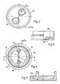
- Figure 2 is a plan view of the cap of a two part cuvette, embodying the invention,
- Figure 3 is a section on the line AA of Figure 2,
- Figure 4 is a plan view of the base of the cuvette,
- Figure 5 is a section of the line BB of Figure 4,
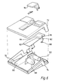
- Figure 6 is a schematic outline of a test instrument for receiving cuvettes of the type shown in Figures 2-5, and
- Figure 7 is a schematic circuit diagram of the instrument of Figure 6.
- In Figure 1 of the drawings, collimated light 10 from a
source 12 is directed towards oneface 14 of a cuvette generally designated 16. Theface 14 includes thereon a grating or a light transmitting hologram having a refractive property similar to a convex lens, as denoted at 18, and contains spherical particles in suspension each of which is coated with a specific binding agent. - If a sample reagent containing a specific binding partner to the specific agent on the surface of the spheres is added to the
cuvette 14, the diameter of the spheres increases and this results in a different light scatter pattern from the cuvette than is the case if the spheres remain at their first diameter. - A large area photodetector or array of photodetectors or television camera or the like is located at 20 and the light scatter pattern is determined by interrogating the detectors or scanning the television camera target and the signal analysed. The circuit means for achieving the analysis is shown at 22.
- A lens 24 located to the rear of the
cuvette 16 focusses any light which has been transmitted through the cuvette without being scattered, to a point at 26 at which it can be conveyed away or blocked so that it forms no part of the image on thedetector 20. Light which has been scattered from one of more of the spheres will be collected by the lens 24 and the light scatter pattern is formed on the large area detector. - The function of the
lens 18 on thefront wall 14 of thecuvette 16 is to divert some of the light incident on the cuvette to an off-axis point 28 at which asecond photocell 30 is located. The electrical signals (if any) from thephotocell 30 are supplied to a detector circuit 32 which normally transmits an inhibit signal to the remainder of the apparatus but in the presence of an electrical signal indicating that light has been received by thephotocell 30 the circuit means 32 generates an enable signal to thereby enable the remainder of the apparatus to perform an assay. - In particular the inhibit signal and enable signals are applied to the circuit means 22.
- The
cuvette 16 is mounted so as to be rotated by anelectric motor 34 through the intermediatry of arubber drive wheel 35. Drive for the motor is effected automatically from operation of thestart button switch 38 associated withcontrol circit 36. Appropriate interlocks and proximity switching means is provided so thatcircuit 36 is only enabled after a cuvette has been satisfactorily positioned within the holder (not shown). Thereafterdepressing button switch 38 will cause themotor 34 to rotate and thereby rotate the holder (not shown) through 360°. Simultaneously thecontrol circuit 36 provides power to thelight source 12 and further enables the circuit 32 for the duration of the 360° rotation. - In the event that a cuvette having a
holographic lens 18 has been inserted within the carrier, and the cuvette has been located the correct way round, theholographic lens 18 will produce a spot of light which will intercept thedetector 30 at some point during the rotation of the cuvette and produce a signal in the output of thedetector 30 which will remove the inhibit signal in the output circuit means 32 and replace it with an enable signal. The latter then enables circuit 22.(and if - If it is necessary to manually add the test sample this may now be added and the enabling signal man also enable visible or audible indicator means to indicate to the user that the sample reagent can now be added to the cuvette. The addition may be by means of a hypodermic syringe. Alternatively the sample addition may be automatic, from a reservoir or injector associated with the apparatus (not shown), or may occur as a result of shaking or rotating the cuvette.
- In place of the
large area detector 20, two detectors may be located in a plane perpendicular to theaxis 40. Two such detectors are shown at 42 and 44. By moving the twodetectors axis 40 towards and away from the cuvette, so the light scatter pattern intensity can be determined by summing the outputs from the twodetectors - The
cuvette 48 shown in Figures 2 to 5 is a two chamber device containing test latex in onechamber 50 and control latex in aseparate chamber 52. - The cuvette includes a
base 54 and acap 56. The cap contains two ski-slope pockets (one of which is shown at 58) which contain the dried latex and which prevent its wetting until the cuvette is inverted. The chamber shape and size can help control the size of the mixing bubble and allow it to move smoothly around the chamber. A drainage groove is provided at 59. - A
location feature 60 is provided on the cap and asimilar feature 62 is provided on the base to control the relative orientation of cap and base +/-6°. This allows a minimum vent area of 0.2mm² during closure of the cuvette. This prevents aerosol formation and the vent is closed once assembly of the cap and base has been completed. - Visual guide features may be added to the location feature, to make it easier to orientate by eye.
- Two 4mm diameter gratings are provided at 64 and 66 and positioned on the external face, concentrically with two 4mm diameter viewing windows, one of which is shown at 68. The grating over the 'control'
chamber 52 is orientated radially whilst that over the "reaction"chamber 50 is orientated tangentially, thus allowing the instrument to distinguish between light from the "control" and "reaction" chambers. - The gratings typically have a nominal groove spacing of 2.33u which produce a deflection angle of 25°. The optimum 0.25u nominal grating depth gives a nominal design diffraction efficiency for the grating of 14% at 940mm.
- There may be loss of diffraction efficiency with moulded gratings but diffraction efficiencies of greater than approximately 5% have been found to give acceptablegrating signals from an agglutinating sample in the instrument.
- To achieve acceptable bubble mobility cuvettes may be plasma etched in batches, and may be treated with oxygen plasma for a period of time (typically 3 minutes) per batch.
- As shown in Figure 6 the instrument is a small desk-top unit formed from a two-
part moulding tight lid 76 accepts cuvettes for analysis. A liquidcrystal display unit 78 is used to convey information to the operator, such as; pass/fail/test again/dilute/battery low, cuvette jammed, etc. Threebuttons internal cells 70 recharged from an external low voltage transformer. - The three
buttons 80 82, 84 arranged under the display, allow selection of algorithm and control the operation of the instrument. - One of the
buttons 80 applies power to the unit. It is a toggle action switch, ie. push on and push off. This button is also used to abort a test. -
Button 82 is used to scroll the algorithm number in the display. The selected algorithm will then be used to test data from the cuvette for pass/fail. -
Button 84 is a down scroll button and is used in the same way as thebutton 82, to reduce the algorithm number. - The unit is turned on by pushing on/off
switch 80. When power is applied the display will show the following: - algorithm 1
- if the battery power is low the battery symbol is displayed
- all other displays will be invisible
- To conduct a test the user performs the following sequence:
- the test unit is switched on by pressing
switch 80; - the operator first adds the sample material to the
cuvette chambers - the
lid 70 over the cuvette opening is opened; - the up scroll and down
scroll buttons - the cuvette is sealed and placed into the instrument and the lid closed. The action of closing the lid causes the instrument to start operation, ie. apply power to the
LED 86 andmotor 88 and enable the data collection system; - an internal timer and microprocessor controls the measurement sequence, and at the end of the measurement time, (as dictated by the algorithm number), the display will indicate Pass/Fail or Retest - (meaning test again). During the test the display shows a countdown sequence to indicate progress of the test.
- the system is turned off by pushing the on/off
switch 80 again. The display will then blank. All internal data is lost on turn-off. - When an estimated 10 minutes of battery life is left, the battery symbol will become visible.
- The instrument uses optical diffraction to measure the rate of agglutination. A collimated beam of light falling on the latex spheres in suspension in the cuvette will cause some of the light to be diffracted from the main collimated beam. As the agglutination occurs then the effective sphere diameter increases, causing the angular distribution and the intensity of scattered light to be reduced. Circuits within the test instrument compare the rate of change of the scattered light from the test chamber and the control chamber to provide the assessment.
- A simple silicon photodiode is mounted on a p.c.b. 90 and is used to monitor the intensity of scattered light. This phototide is placed at 3.5mm from the optical axis of the system. This has been shown to provide the optimum, sensitivity. The detector used is a 1mm² detector.
- The grating detectors are similar photodivides placed approximately 11mm from the optical axis. These detectors are designed to sense the diffracted portion of the collimated beam from the gratings. Two detectors are used, one at top-dead centre and the other at 90°. One detector is triggered by the grating for the test chamber, and the other by the grating for the control chamber.
- Two lenses are used, although not shown in Figure 6. A collimating lens and an aperture is used to provide a collimated beam from the LED source to interrogate the cuvette. A second lens is used to collect the scattered light. The two lenses are 25mm focal length and are of moulded plastic. The effect of the focussing lens on the diffracted beam from the grating is to create a spot 2.5 x 1mm at the grating detector plane.
- The cuvette has to be rotated within the instrument to allow mixing of the sample and latex material. By synchronising the measurements with the rotation a single optical system can be used to examine both test and control chambers.
- A six
volt DC motor 88 andgear box 92 provides the necessary rotational drive. - A magnetic coupling (not shown) is used to transmit the drive to the drive wheel within the rotation assembly which can be removed for ease of cleaning in the event of spillage of bioactive materials.
- The rotation rate of the cuvette is of the order of 15 rpm.
- The electrical control and measuring and display circuits of the test unit are shown schematically in Figure 7.
- For convenience a
single chip computer 94 manages the following functions:- - reading the
buttons 80 82, 84; - providing the control data for the
LCD indicator 78; - controlling the
motor 88; - controlling the
security LED 96 and measurementlight source LED 98; - reading the
security photodiode 100 andgrating photodiodes - computing a value according to an algorithm stored in EPROM (within 94) and thereby generating a pass/fail condition based on the measured data.
- A test is initiated by closing the
lid 76 at which point LED,drivers 106 are switched on. Current requirements of LED are relatively high, and power can be conserved by only turning the LEDs on during measurements. Thedrivers 106 operate so as to provide constant current to the LEDs to ensure constant light output. - The outputs from the
grating photodiodes selector 108 to provide a clock signal to theprocessing unit 94. The presence of the clock signal indicates that the appropriate chamber is in the optical beam and that a reading from the signal diode will be valid. The signals are amplified byamplifier 110 and the amplified signals are digitised by A/D converter 112 and presented to theprocessor unit 94 for analysis. - A
display driver 114 controls the display of digits in thedisplay unit 78, so as to provide information to the operator on the instrument status and battery condition as well as the algorithm selected and the test result. - The
motor 80 is only activated when a test is in progress so as to conserve battery life, and a constant current for the motor is obtained fromdrives 106 and PWR amplifier 116 to maintain a constant motor speed. - The batteries are charged by an external low voltage charging unit (not shown).
- Where it is necessary to provide for the instrument to be interfaced to a computer, an
RS 232 interface is provided. The data to be transmitted through theRS 232 link may contain information on the time that a sample was measured, and the voltage level of that sample. - The decision on whether a particular sample has passed or failed a test will be made by measuring the rate of change of the signal falling on the signal photodiode, since this gradient appears to be a good indicator of infection.
- The
casing parts lid 76 must be light tight. The space occupied by the cuvette and magnetically coupled drive wheel must be capable of being cleaned by flushing with alcohol or other sterilising agents. A feature of the lid mechanism is that it is preferred that when then lid is opened the cuvette will be ejected into an exit channel. This will allow the next cuvette to be loaded before final removal of the last cuvette. - Reagent types which can be used with the instrument can be found in the Orion Diagnostica's range of reagent kits, ie Rotalex, Adenalex, Hemolex, Rubalex, Respiralex and Myolex.
- A number of algorithms sufficient to satisfy Orion Diagnostica's range of test kits are stored in a PROM section of the
processor 94.
Claims (16)
means for moving the illumination means in a predictable manner during at least a preliminary movement of the cuvette;
a light sensitive detector (30) for checking for the presence of light at a point along a path along which light will be diverted if the cuvette (16) includes the appropriate optical element (18); and
circuit means (32) responsive to electrical signals from the light sensitive detector (30) which normally inhibits the operation of the apparatus to perform the said assay (or at least inhibits the inspection of the change in light scattering properties of the cuvette contents), but which generates an enabling signal to permit the apparatus to perform the assay if an appropriate signal is generated by the detector (30) during the said preliminary movement of the cuvette (16), the appropriate signal being generated if the detector (30) detects the presence of light.
a plurality of light sensitive detectors (42, 44) mounted to the rear of the cuvette (16), and
means (12) for illuminating the cuvette so as to produce a light scatter pattern for detection by the plurality of detectors (42, 44).
Characterised by the steps of:
Priority Applications (1)
| Application Number | Priority Date | Filing Date | Title |
|---|---|---|---|
| AT88904998T ATE76971T1 (en) | 1987-06-11 | 1988-06-13 | CUEVETTE AND APPARATUS FOR PERFORMING BIOLOGICAL DETECTIONS. |
Applications Claiming Priority (2)
| Application Number | Priority Date | Filing Date | Title |
|---|---|---|---|
| GB878713649A GB8713649D0 (en) | 1987-06-11 | 1987-06-11 | Biological assay |
| GB8713649 | 1987-06-11 |
Publications (2)
| Publication Number | Publication Date |
|---|---|
| EP0328563A1 EP0328563A1 (en) | 1989-08-23 |
| EP0328563B1 true EP0328563B1 (en) | 1992-06-03 |
Family
ID=10618736
Family Applications (1)
| Application Number | Title | Priority Date | Filing Date |
|---|---|---|---|
| EP88904998A Expired EP0328563B1 (en) | 1987-06-11 | 1988-06-13 | Cuvette and apparatus for performing biological assays |
Country Status (9)
| Country | Link |
|---|---|
| US (1) | US5100238A (en) |
| EP (1) | EP0328563B1 (en) |
| JP (1) | JP2681295B2 (en) |
| AT (1) | ATE76971T1 (en) |
| AU (1) | AU1805888A (en) |
| DE (1) | DE3871768T2 (en) |
| FI (1) | FI96637C (en) |
| GB (1) | GB8713649D0 (en) |
| WO (1) | WO1988009925A1 (en) |
Families Citing this family (42)
| Publication number | Priority date | Publication date | Assignee | Title |
|---|---|---|---|---|
| IT1246993B (en) * | 1991-01-10 | 1994-12-12 | Diesse Diagnostica | TEST TUBE FOR BIOLOGICAL ANALYSIS EQUIPPED WITH CONTROL DEVICE, EFFICIENCY AND POSITION, FOR PHOTOMETRIC READINGS. |
| US5192510A (en) * | 1991-01-30 | 1993-03-09 | E. I. Du Pont De Nemours And Company | Apparatus for performing fluorescent assays which separates bulk and evanescent fluorescence |
| US7714301B2 (en) * | 2000-10-27 | 2010-05-11 | Molecular Devices, Inc. | Instrument excitation source and calibration method |
| US7098041B2 (en) * | 2001-12-11 | 2006-08-29 | Kimberly-Clark Worldwide, Inc. | Methods to view and analyze the results from diffraction-based diagnostics |
| US7102752B2 (en) * | 2001-12-11 | 2006-09-05 | Kimberly-Clark Worldwide, Inc. | Systems to view and analyze the results from diffraction-based diagnostics |
| EP1499877B1 (en) * | 2002-04-22 | 2009-04-15 | Hans Joachim Bruins | Measuring device, particularly for conducting spectroscopic measurements |
| DE10217838A1 (en) * | 2002-04-22 | 2003-11-13 | Hans Joachim Bruins | Measuring device for spectroscopic measurements has measuring cuvette supported for rotation about non-vertical rotation axis for mixing particulate or fluid sample |
| US7900836B2 (en) * | 2002-08-20 | 2011-03-08 | Illumina, Inc. | Optical reader system for substrates having an optically readable code |
| US7508608B2 (en) * | 2004-11-17 | 2009-03-24 | Illumina, Inc. | Lithographically fabricated holographic optical identification element |
| US7872804B2 (en) * | 2002-08-20 | 2011-01-18 | Illumina, Inc. | Encoded particle having a grating with variations in the refractive index |
| US20050227252A1 (en) * | 2002-08-20 | 2005-10-13 | Moon John A | Diffraction grating-based encoded articles for multiplexed experiments |
| US7441703B2 (en) * | 2002-08-20 | 2008-10-28 | Illumina, Inc. | Optical reader for diffraction grating-based encoded optical identification elements |
| US7619819B2 (en) | 2002-08-20 | 2009-11-17 | Illumina, Inc. | Method and apparatus for drug product tracking using encoded optical identification elements |
| JP4485949B2 (en) * | 2002-08-20 | 2010-06-23 | シヴェラ コーポレイション | Grating-based coded microparticles for multiplex experiments |
| US7901630B2 (en) * | 2002-08-20 | 2011-03-08 | Illumina, Inc. | Diffraction grating-based encoded microparticle assay stick |
| US7164533B2 (en) * | 2003-01-22 | 2007-01-16 | Cyvera Corporation | Hybrid random bead/chip based microarray |
| EP1535241A1 (en) * | 2002-08-20 | 2005-06-01 | Cyvera Corporation | Diffraction grating-based optical identification element |
| US7923260B2 (en) | 2002-08-20 | 2011-04-12 | Illumina, Inc. | Method of reading encoded particles |
| AU2003270655A1 (en) * | 2002-09-12 | 2004-04-30 | Cyvera Corporation | Assay stick comprising coded microbeads |
| US20100255603A9 (en) * | 2002-09-12 | 2010-10-07 | Putnam Martin A | Method and apparatus for aligning microbeads in order to interrogate the same |
| AU2003274979A1 (en) * | 2002-09-12 | 2004-04-30 | Cyvera Corporation | Chemical synthesis using diffraction grating-based encoded optical elements |
| US7092160B2 (en) * | 2002-09-12 | 2006-08-15 | Illumina, Inc. | Method of manufacturing of diffraction grating-based optical identification element |
| EP1540591A1 (en) * | 2002-09-12 | 2005-06-15 | Cyvera Corporation | Diffraction grating-based encoded micro-particles for multiplexed experiments |
| AU2003267192A1 (en) * | 2002-09-12 | 2004-04-30 | Cyvera Corporation | Method and apparatus for aligning elongated microbeads in order to interrogate the same |
| CA2499037A1 (en) * | 2002-09-12 | 2004-03-25 | Cyvera Corporation | Method and apparatus for labelling using diffraction grating-based encoded optical identification elements |
| US7247500B2 (en) * | 2002-12-19 | 2007-07-24 | Kimberly-Clark Worldwide, Inc. | Reduction of the hook effect in membrane-based assay devices |
| US7851209B2 (en) * | 2003-04-03 | 2010-12-14 | Kimberly-Clark Worldwide, Inc. | Reduction of the hook effect in assay devices |
| US20040258563A1 (en) | 2003-06-23 | 2004-12-23 | Applera Corporation | Caps for sample wells and microcards for biological materials |
| US20060057729A1 (en) * | 2003-09-12 | 2006-03-16 | Illumina, Inc. | Diffraction grating-based encoded element having a substance disposed thereon |
| US7433123B2 (en) | 2004-02-19 | 2008-10-07 | Illumina, Inc. | Optical identification element having non-waveguide photosensitive substrate with diffraction grating therein |
| US20060019265A1 (en) * | 2004-04-30 | 2006-01-26 | Kimberly-Clark Worldwide, Inc. | Transmission-based luminescent detection systems |
| US20050244953A1 (en) * | 2004-04-30 | 2005-11-03 | Kimberly-Clark Worldwide, Inc. | Techniques for controlling the optical properties of assay devices |
| US7815854B2 (en) * | 2004-04-30 | 2010-10-19 | Kimberly-Clark Worldwide, Inc. | Electroluminescent illumination source for optical detection systems |
| US7796266B2 (en) * | 2004-04-30 | 2010-09-14 | Kimberly-Clark Worldwide, Inc. | Optical detection system using electromagnetic radiation to detect presence or quantity of analyte |
| US7604173B2 (en) * | 2004-11-16 | 2009-10-20 | Illumina, Inc. | Holographically encoded elements for microarray and other tagging labeling applications, and method and apparatus for making and reading the same |
| WO2006055735A2 (en) | 2004-11-16 | 2006-05-26 | Illumina, Inc | Scanner having spatial light modulator |
| EP1869615B1 (en) * | 2004-11-16 | 2010-03-03 | Illumina, Inc. | Methods and apparatus for reading coded microbeads |
| US20070121113A1 (en) * | 2004-12-22 | 2007-05-31 | Cohen David S | Transmission-based optical detection systems |
| US7623624B2 (en) * | 2005-11-22 | 2009-11-24 | Illumina, Inc. | Method and apparatus for labeling using optical identification elements characterized by X-ray diffraction |
| US7830575B2 (en) * | 2006-04-10 | 2010-11-09 | Illumina, Inc. | Optical scanner with improved scan time |
| EP2355930B1 (en) | 2008-11-06 | 2018-01-10 | Koninklijke Philips N.V. | Cuvette and method for authenticating a cuvette |
| US10324023B1 (en) * | 2015-12-14 | 2019-06-18 | Spectroclick, Inc. | Energy dispersion cuvette |
Family Cites Families (10)
| Publication number | Priority date | Publication date | Assignee | Title |
|---|---|---|---|---|
| US3512877A (en) * | 1967-11-17 | 1970-05-19 | Zeiss Jena Veb Carl | Optical multiple-reflection systems |
| US4372683A (en) * | 1979-09-04 | 1983-02-08 | Beckman Instruments, Inc. | Photometer with rotating sample container |
| JPS57182651A (en) * | 1981-05-07 | 1982-11-10 | Olympus Optical Co Ltd | Detection apparatus of particle agglomeration pattern |
| US4371498A (en) * | 1981-06-19 | 1983-02-01 | Medical Laboratory Automation, Inc. | Coded cuvette for use in testing apparatus |
| US4452902A (en) * | 1981-11-19 | 1984-06-05 | Labsystems Oy | Method and equipment for the measurement of properties of a liquid |
| JPS58172537A (en) * | 1982-04-04 | 1983-10-11 | Wako Pure Chem Ind Ltd | Apparatus for measuring light scattering |
| JPS6040937A (en) * | 1983-08-16 | 1985-03-04 | Shimadzu Corp | Immune reaction measuring device |
| US4566791A (en) * | 1983-10-31 | 1986-01-28 | Pacific Scientific Company | Fluid sample cell comprising Fresnel sectors |
| DE3535652A1 (en) * | 1984-11-01 | 1986-04-30 | Jenoptik Jena Gmbh, Ddr 6900 Jena | ARRANGEMENT FOR OPTICAL RADIATION IN PHOTOMETRIC ANALYZER MEASURING DEVICES |
| US4842406A (en) * | 1988-01-15 | 1989-06-27 | Pacific Scientific Company | Optical instruments for measuring particle sizes |
-
1987
- 1987-06-11 GB GB878713649A patent/GB8713649D0/en active Pending
-
1988
- 1988-06-13 WO PCT/GB1988/000457 patent/WO1988009925A1/en not_active Ceased
- 1988-06-13 DE DE8888904998T patent/DE3871768T2/en not_active Expired - Fee Related
- 1988-06-13 US US07/317,474 patent/US5100238A/en not_active Expired - Fee Related
- 1988-06-13 JP JP63504726A patent/JP2681295B2/en not_active Expired - Fee Related
- 1988-06-13 AU AU18058/88A patent/AU1805888A/en not_active Abandoned
- 1988-06-13 EP EP88904998A patent/EP0328563B1/en not_active Expired
- 1988-06-13 AT AT88904998T patent/ATE76971T1/en not_active IP Right Cessation
-
1989
- 1989-02-08 FI FI890591A patent/FI96637C/en active IP Right Grant
Also Published As
| Publication number | Publication date |
|---|---|
| JPH01503566A (en) | 1989-11-30 |
| GB8713649D0 (en) | 1987-07-15 |
| DE3871768D1 (en) | 1992-07-09 |
| WO1988009925A1 (en) | 1988-12-15 |
| JP2681295B2 (en) | 1997-11-26 |
| DE3871768T2 (en) | 1993-01-14 |
| FI890591A7 (en) | 1989-02-08 |
| FI890591A0 (en) | 1989-02-08 |
| US5100238A (en) | 1992-03-31 |
| AU1805888A (en) | 1989-01-04 |
| FI96637C (en) | 1996-07-25 |
| ATE76971T1 (en) | 1992-06-15 |
| FI96637B (en) | 1996-04-15 |
| EP0328563A1 (en) | 1989-08-23 |
Similar Documents
| Publication | Publication Date | Title |
|---|---|---|
| US5100238A (en) | Cuvette and apparatus for performing biological assays | |
| US5478750A (en) | Methods for photometric analysis | |
| US4683120A (en) | Biological fluid assay system | |
| CA2251629C (en) | Nephelometer and turbidimeter combination | |
| AU641130B2 (en) | Coded cuvette for use in testing apparatus | |
| US10113962B2 (en) | Automatic analyzer | |
| US4599315A (en) | Microdroplet test apparatus | |
| US6336358B1 (en) | Method and apparatus for measuring sedimentation rate of sediments in liquid sample | |
| US5292484A (en) | Cuvette and cuvette cartridge for a chemical analyzer | |
| JP6208356B2 (en) | Automatic analyzer | |
| JPS62175649A (en) | Method of measuring luminous intensity, photometer and method of measuring hla type of cell | |
| US5283178A (en) | Method of forming agglutinates in blood samples | |
| CN103033634A (en) | Sample processing apparatus | |
| US20210402400A1 (en) | Hematology test slide | |
| US4597944A (en) | Agglutination reagent detection system | |
| WO2002016043A1 (en) | Centrifugal separator and analyzer with the separator | |
| US10852312B2 (en) | Determination method of blood sample, blood sample analyzer, and computer program | |
| JP3157601B2 (en) | Automatic blood analyzer | |
| JP2779824B2 (en) | Immunological agglutination detector | |
| JPH07260797A (en) | Distribution device | |
| JP2023512091A (en) | Instruments, systems and methods for measuring properties of samples | |
| US20210356484A1 (en) | Specimen treatment system | |
| KR20180077820A (en) | Blood cell analysis apparatus, blood specimen and container detecting method thereof | |
| CN101229530B (en) | Centrifugal separator | |
| JPH09236600A (en) | Method and apparatus for measuring fecal occult blood |
Legal Events
| Date | Code | Title | Description |
|---|---|---|---|
| PUAI | Public reference made under article 153(3) epc to a published international application that has entered the european phase |
Free format text: ORIGINAL CODE: 0009012 |
|
| 17P | Request for examination filed |
Effective date: 19890216 |
|
| AK | Designated contracting states |
Kind code of ref document: A1 Designated state(s): AT BE CH DE FR GB IT LI LU NL SE |
|
| 17Q | First examination report despatched |
Effective date: 19910111 |
|
| RAP1 | Party data changed (applicant data changed or rights of an application transferred) |
Owner name: ORION CORPORATION LIMITED |
|
| GRAA | (expected) grant |
Free format text: ORIGINAL CODE: 0009210 |
|
| ITF | It: translation for a ep patent filed | ||
| AK | Designated contracting states |
Kind code of ref document: B1 Designated state(s): AT BE CH DE FR GB IT LI LU NL SE |
|
| PG25 | Lapsed in a contracting state [announced via postgrant information from national office to epo] |
Ref country code: SE Effective date: 19920603 Ref country code: BE Effective date: 19920603 Ref country code: AT Effective date: 19920603 |
|
| REF | Corresponds to: |
Ref document number: 76971 Country of ref document: AT Date of ref document: 19920615 Kind code of ref document: T |
|
| PG25 | Lapsed in a contracting state [announced via postgrant information from national office to epo] |
Ref country code: LU Free format text: LAPSE BECAUSE OF NON-PAYMENT OF DUE FEES Effective date: 19920630 |
|
| REF | Corresponds to: |
Ref document number: 3871768 Country of ref document: DE Date of ref document: 19920709 |
|
| ET | Fr: translation filed | ||
| PG25 | Lapsed in a contracting state [announced via postgrant information from national office to epo] |
Ref country code: GB Effective date: 19920903 |
|
| PG25 | Lapsed in a contracting state [announced via postgrant information from national office to epo] |
Ref country code: NL Effective date: 19930101 |
|
| NLV4 | Nl: lapsed or anulled due to non-payment of the annual fee | ||
| PLBE | No opposition filed within time limit |
Free format text: ORIGINAL CODE: 0009261 |
|
| STAA | Information on the status of an ep patent application or granted ep patent |
Free format text: STATUS: NO OPPOSITION FILED WITHIN TIME LIMIT |
|
| GBPC | Gb: european patent ceased through non-payment of renewal fee |
Effective date: 19920903 |
|
| 26N | No opposition filed | ||
| PGFP | Annual fee paid to national office [announced via postgrant information from national office to epo] |
Ref country code: FR Payment date: 20030512 Year of fee payment: 16 |
|
| PGFP | Annual fee paid to national office [announced via postgrant information from national office to epo] |
Ref country code: CH Payment date: 20030519 Year of fee payment: 16 |
|
| PGFP | Annual fee paid to national office [announced via postgrant information from national office to epo] |
Ref country code: DE Payment date: 20030527 Year of fee payment: 16 |
|
| PG25 | Lapsed in a contracting state [announced via postgrant information from national office to epo] |
Ref country code: LI Free format text: LAPSE BECAUSE OF NON-PAYMENT OF DUE FEES Effective date: 20040630 Ref country code: CH Free format text: LAPSE BECAUSE OF NON-PAYMENT OF DUE FEES Effective date: 20040630 |
|
| PG25 | Lapsed in a contracting state [announced via postgrant information from national office to epo] |
Ref country code: DE Free format text: LAPSE BECAUSE OF NON-PAYMENT OF DUE FEES Effective date: 20050101 |
|
| REG | Reference to a national code |
Ref country code: CH Ref legal event code: PL |
|
| PG25 | Lapsed in a contracting state [announced via postgrant information from national office to epo] |
Ref country code: FR Free format text: LAPSE BECAUSE OF NON-PAYMENT OF DUE FEES Effective date: 20050228 |
|
| REG | Reference to a national code |
Ref country code: FR Ref legal event code: ST |
|
| PG25 | Lapsed in a contracting state [announced via postgrant information from national office to epo] |
Ref country code: IT Free format text: LAPSE BECAUSE OF NON-PAYMENT OF DUE FEES Effective date: 20050613 |