EP0328149A2 - Device for the representation of braille writing - Google Patents
Device for the representation of braille writing Download PDFInfo
- Publication number
- EP0328149A2 EP0328149A2 EP89102377A EP89102377A EP0328149A2 EP 0328149 A2 EP0328149 A2 EP 0328149A2 EP 89102377 A EP89102377 A EP 89102377A EP 89102377 A EP89102377 A EP 89102377A EP 0328149 A2 EP0328149 A2 EP 0328149A2
- Authority
- EP
- European Patent Office
- Prior art keywords
- carrier
- pins
- feeler pins
- feeler
- locking elements
- Prior art date
- Legal status (The legal status is an assumption and is not a legal conclusion. Google has not performed a legal analysis and makes no representation as to the accuracy of the status listed.)
- Granted
Links
Images


Classifications
-
- G—PHYSICS
- G09—EDUCATION; CRYPTOGRAPHY; DISPLAY; ADVERTISING; SEALS
- G09B—EDUCATIONAL OR DEMONSTRATION APPLIANCES; APPLIANCES FOR TEACHING, OR COMMUNICATING WITH, THE BLIND, DEAF OR MUTE; MODELS; PLANETARIA; GLOBES; MAPS; DIAGRAMS
- G09B21/00—Teaching, or communicating with, the blind, deaf or mute
- G09B21/02—Devices for Braille writing
Definitions
- the invention relates to a device for displaying braille according to the preamble of claim 1.
- the arrangement requires a relatively large height and allows only a limited modular structure.
- the bending strips which run essentially parallel to the axis of the feeler pins, are exposed to a high kink load, which can easily lead to breakage and therefore to annoying malfunctions in the sensitive ceramic material.
- Electromechanical drive or release devices have also been proposed to either bring spring-loaded feeler pins to the raised position or to hold them.
- DE-A-2 364 342 shows a module arrangement with magnetic cores or anchors located under the feeler pins, which can be raised by means of individually controlled magnetic coils.
- a mechanical lock is provided for holding, which can be displaced transversely to the axial direction of the cores and the feeler pins with a larger locking magnet against a leaf spring.
- the space requirement of the electromagnets and their mutual influence complicates the realization of this construction, which moreover builds quite high and only provides the cross bar for supporting raised pins, which is hardly suitable for absorbing larger forces - such as for printing set patterns.
- An important aim of the invention is to improve a device of the type mentioned at the outset with simple and economical means in such a way that the flatest possible structure of selectable surface area can be created so that a desired lettering field size can be produced on a case-by-case basis. Furthermore, the invention aims to provide an operationally reliable arrangement with few components, which can be used as a reader or for printing set patterns as required.
- the invention is characterized in that the device is composed of modules, each of which consists of an upper part guiding the feeler pins and a height-adjustable lower support which has the lifting or lowering device for the feeler pins or forms itself.
- the movable carrier holds or forms the lifting and lowering device for the feeler pins, which can therefore be set in a simple manner. A set pattern can only be deleted by changing the height of the beam; however, as long as it remains in its position, a set pattern remains.
- the module structure enables the creation of text fields of the desired size by simply lining up the individual elements, which can be made quite flat.
- the device is robust and can also be used permanently for printing purposes.
- the carrier is movably mounted on or in the upper part and in particular can be pivoted at least at a small angle.
- the position of the carrier relative to the upper part can expediently be adjusted by means of an eccentric. This can be done by hand or by motor, for example by means of a crank, a stepper motor or the like.
- a favorable further development consists according to claim 4 in that the carrier has pedestals which are assigned to the bottom surfaces of the feeler pins and which face the cover plate of the upper part essentially parallel. If the carrier is lowered, the feeler pins with their bottom surfaces on the pedestals slide back in their cover plate guide. In each case two adjacent feeler pins can be supported on the same platform level. It is particularly expedient if, according to claim 6, a number of platforms, in particular four, are arranged in a step-like manner at one end of the carrier. One then uses feeler pins of correspondingly different lengths, namely in four lengths, so that a uniform overhang of the tips of raised feeler pins can be achieved with respect to the outer surface of the cover plate.
- a bushing or double bushing leading the lower end of the supported feeler pin or pair of feeler pins is arranged above each platform.
- the latter are expediently widened according to claim 8, especially weakly conical, to promote the mobility of the stylus when changing the winding due to the pivoting of the carrier.
- the carrier simultaneously holds the locking and unlocking device. Additional elements are therefore not required. Rather, channels or grooves can be present in the carrier at the same height as the platforms, which hold and / or guide locking elements running transversely to the bushings. Such a structure is extremely simple and can be realized with very small dimensions, so that the modules can be made correspondingly narrow and flat. As a result, the device according to the invention is very compact.
- the front ends of the locking elements can each be moved at least up to below the axis of the associated socket, so that each sensor pin in the raised position at least on half of its bottom surface is supported.
- the locking elements are anchor tappets, which are loaded by springs towards the platforms and can be retracted against the spring force by means of magnetic coils.
- the magnetic coils and the springs can be attached according to claim 14 in the channels or grooves of the carrier.
- Adjacent magnetic coils can be used with opposite poles, which makes magnetic inferences easy. Since the magnetic coils are arranged transversely to the direction of movement of the feeler pins, in contrast to conventional technology, considerable savings are made in terms of overall height.
- a preferred embodiment of the invention for which independent protection is claimed, provides according to claim 15 that the locking elements are in particular piezoceramic bending strips, the free ends of which can be pivoted in from the side under the respectively assigned bushings and can be pivoted away from them to the side .
- the locking elements are in particular piezoceramic bending strips, the free ends of which can be pivoted in from the side under the respectively assigned bushings and can be pivoted away from them to the side .
- Such an arrangement has the great advantage that the bending strips even elastic elements and special springs are therefore unnecessary. This contributes significantly to increased operational reliability and also makes very small dimensions possible.
- a bending strip e.g. bimetallic elements can also be used according to the invention, preferably piezoceramic strips are used which respond very quickly and do not generate or have to be dissipated when they are actuated.
- the measure of claim 16 ensures on the one hand low susceptibility to breakage and on the other hand high susceptibility to breakage Pressure resistance of the styli. It is also possible to get by with a small travel range, and that without bending the bending strips.
- the locking elements are expediently provided with electrical connections at their rear ends. This enables the magnet coils or piezoceramic bending strips or the like. supply the control or operating voltage in a simple manner. Since the locking elements sit in the channels or grooves of the wearer, the ends can run freely and e.g. by soldering lugs, wires or the like. continue. It contributes to the stability of the arrangement if the bending strips are mechanically fixed with their connecting ends in the channels or grooves. This also increases the contact security, since there is no movement at the connections themselves.
- the invention further provides according to claim 19 that the carrier holds a control board conductively connected to the electrical connections. As a result, there are no relative movements on the carrier to control the individual locking elements.
- flexible conductors can lead to another circuit board or electrical circuit board which, according to claim 20, is attached to the upper part for the power supply.
- the fixed wiring possible there allows conventional connecting elements to be provided which are used for the electrical connection of the modules to one another and to a control part.
- feeler pins can be formed in one piece, for example from glass fiber reinforced plastic. Cylindrical pins with only one flange are sufficient. However, it should be noted that metal pins are also suitable according to the invention.
- each module has side walls with a bearing bore which receives an axis or shaft holding the carrier.
- the axis or shaft can be designed according to claim 24 as a flattened eccentric, which is seated in a bearing recess of the carrier and has at least one approximately flat contact surface.
- This arrangement allows the height of the carrier to be adjusted in a very simple manner. If necessary, the point height of the pens can be adapted to special requests.
- a stop for limiting the change in height of the carrier is expediently arranged on the carrier and / or on the upper part.
- the carrier is spring-loaded according to claim 26, especially towards the upper part.
- a restoring force acts which only needs to be released in order to bring about a desired countermovement of the wearer.
- the invention provides according to claim 27 that the modules of the device have a common leaf spring, which acts on all carriers. Therefore, each individual pin is supported on the carrier particularly firmly and can withstand high loads accordingly. At the same time, it is ensured that the individual locking elements of the pins set are loaded only slightly.
- the module shown in FIGS. 1 and 2, generally designated 10, consists of an upper part 12 and a carrier 30 which - as indicated schematically in FIG. 1 by a double arrow - is movable up and down relative to the upper part.
- a rod holder 46 can be provided, which can be moved in height by a mechanism (not shown).
- the upper part 12 has a cover plate 14, in which feeler pins 18 are guided, in parallel bores.
- the feeler pins 18 have crests 20 which, in the raised position of the feeler pins 18, protrude beyond the outer surface 16, but disappear in the cover plate 14 in the lowered position of the feeler pins 18.
- the feeler pins 18 each have a flange 22 on which a compression spring 24 is supported, which surrounds the feeler pin 18 in the upper region and on the inner surface of the cover plate 14 you find abutment.
- the flanges 22 can rest on a holder plate 28 embedded in the cover plate 14 at the bottom.
- the feeler pins 18 continue in predetermined lengths. Their bottom surfaces 26 can come to rest on pedestals 32 of the carrier 30.
- the feeler pins 18 are guided vertically in bushings 34 of the carrier 30.
- the guide bores arranged therein are vertical for the feeler pins 18 and thus for these themselves.
- the bushes 34 are arranged vertically in the carrier 30.
- the platforms 32 and the channels or grooves 36 with the same height in the carrier 30 run horizontally, that is to say transversely to the feeler pins 18.
- Magnetic coils 38 are located in the channels or grooves 36, preferably with alternating opposite polarity.
- Armature plungers 40 are axially movable in the interior of the magnet coils 38, which are supported with springs 42 at one end of the channels or grooves 36, where the connections 52 of the magnet coils 38 are also arranged.
- the springs 42 load the armature plungers 40 towards the respectively assigned feeler pins 18.
- the channels or grooves 36 in the support 30 form a step-like arrangement and are staggered so that each anchor plunger can penetrate into an associated socket 34 and find its stop therein. If the carrier 30 is now lowered relative to the upper part 12, the flanges 22 of the feeler pins 18 come to bear on the holding plate 28, while the bottom surface 26 of the feeler pins 18 stands out from the support surface in the bracket 30. With sufficient lowering, the compression springs 42 push the anchor plunger 40 forward, ie in each case under the bottom surface 26 of the associated feeler pin 18. When the support 30 is then lifted, all the feeler pins 18 protrude with their crests 20 over the outer surface 16 of the upper part 12.
- an upper part 12 of the module 10 is stationary and a carrier 30 arranged underneath it is vertically movable, as indicated by the double arrow in FIG. 3.
- cylindrical feeler pins 18 are used, which are guided in the upper area with resilient support in the cover plate 14 and in the holding plate 28 so as to be vertically movable. Flanges 22 of the feeler pins 18 can be supported on the latter.
- FIGS. 3 and 4 corresponds to that of FIGS. 1 and 2, but here magnetic coils 38 lie opposite one another in channels 36 of the carrier 30 on the same level. Accordingly, the assigned platforms 32 are also of equal height to one another. It can be seen that in this embodiment a four-point drawing field 48 (FIG. 4) with two pairs of magnets on either side of the four feeler pins 18 is sufficient. Otherwise, the function corresponds to that described above. If a feeler pin 18 is to be fully lowered (left in FIG. 3) so that its bottom surface 26 rests on the pedestal 32, the magnet coil 38 in question is excited and the armature tappet 40 is thereby withdrawn against spring force.
- the compression spring 42 presses the anchor plunger 40 forward so that it projects into the bush 34 and strikes there, provided that the carrier 30th was sufficiently lowered from the upper part 12. If the carrier 30 is then raised, the bottom surface 26 of the relevant stylus 18 comes to rest on the front end of the advanced anchor plunger 40, so that the pin is raised and its tip 20 projects beyond the outer surface 16.
- FIGS. 3 and 4 are suitable for line construction with four-point character fields 48, while the embodiment of FIGS. 1 and 2 - with a somewhat greater overall height - is suitable and intended for the representation of eight-point characters (FIG. 2).
- piezoceramic bending strips 50 which are fixed in the channels 36 of the carrier 30 at the ends provided with connections 52, serve as locking elements (FIG. 6).
- a bending strip 50 rests at rest (on the right in FIGS. 5 and 6) on an inner partition wall of the carrier 30, and a sensing pin 18 is supported with its bottom surface 26 on the free end of this bending strip 50, so that the sensing pin 18 is raised and its tip 20 protrudes over the outer surface 16 of the upper part 12. If electrical voltage is now applied, the state shown in FIGS. 5 and 6 arises.
- the bending strip 50 bends out of its plane and thereby swivels with its free end to the side, whereby the feeler pin 18 in question lowers under the pressure of its spring 24 until the flange 22 strikes the holding plate 28.
- a holding edge 44 of the upper part 12 can serve to fix it on a housing (not shown).
- FIGS. 7a to 7e and FIG. 8 show a further practical embodiment of modules for a device according to the invention.
- the upper part 12 is shown in FIGS. 7a to 7e and FIG. 8, whose cover plate 14 protrudes somewhat upwards here, so that the outer surface 16 with the drawing field 48 lies higher than the other sections of the upper part 12.
- This can be a plastic injection-molded part with side walls 56, in which a bearing bore 58 is present.
- a number of small bores are provided, through which a screw connection, pinning or the like. is possible.
- a free area of the upper part 12 can accommodate a printed circuit board 68 inside or below (FIG. 8), which serves to supply power to a control board 54, which is attached to the associated carrier 30.
- Such a carrier 30 is shown in FIGS. 9a to 9d. It has a bearing recess 62 in an upper region, into which an axis or shaft 60 serving as an eccentric and flattened on one side can be inserted, as indicated in FIGS. 7a and 9a with a schematic cross section. The carrier 30 can then be moved about the axis or shaft 60 until an end designed as a stop 66 arrives at the upper part 12 on the inside. In view of the short travel distances required for lowering or raising the feeler pins 18, a slight pivoting of the carrier 30 is sufficient.
- FIG. 9a and 9b; 10a This is designed in a step-like manner on a front part (FIGS. 9a and 9b; 10a) and is provided with channels 36 which each run horizontally and at the same height with a platform 32.
- a bushing 34 is arranged above the latter, which guides the lower end of the associated feeler pin 18 and is expediently flared upwards in order to ensure its mobility despite the change in the angle of the carrier 30.
- the carrier 30 has a recess for the control board 54 fixedly connected to it (FIGS. 9a and 8). From this, flexible lines (not shown) can lead to the printed circuit board 68, which is provided for the power supply.
- FIGS. 10a and 10b show the support and guide arrangement for the feeler pins 18 on an enlarged scale
- FIGS. 11 and 12 show how piezoceramic bending strips 50, which are arranged upright in the channels or grooves 36 of the carrier 30, and effect unlocking.
- a bending strip 50 is shown at the top in FIG. 11 and at the left in FIG. 12, which grips under and supports the bottom surface of the feeler pin 18 which is in the raised position.
- the lower half of FIG. 11 and the right half of FIG. 12 show an unlocked position, in which the respective feeler pin 18 is lowered after the associated bending strip 50 has been moved to the side under the feeler pin 18 by the application of tension.
- the device according to the invention can be designed comfortably in the way often preferred by blind people, according to which only those signs or points are set which are also intended to immediately convey information, while the reading surface 16 remains empty (so that the crests 20 of the retracted feeler pins 18 are not palpable).
- the module structure creates a very simple and therefore inexpensive reading device for blind people who e.g. for displaying numbers on clocks, thermometers etc., but also for longer texts. If desired, line displays can also be used for printing.
- the control takes place electronically, preferably via a microprocessor, and the power supply can take place via a power supply unit or also with battery supply.
- the carrier 30 is moved, which, thanks to its special design, can be carried out in a flat design and with a low weight.
- the locking elements 38, 40; 50 across the feeler pins 18 so that their locking and unlocking is fast and stable.
- only a few components are required, which can also be assembled into assemblies of any size or small size.
- feeler pins 18 In the fixed upper part 12, lowered feeler pins 18 come to rest with their flange 22 on the holding plate 28. This absorbs the compressive forces of the springs 24 when the carrier 30 is lifted down. Then the locking elements 40, 50 can be actuated and actuated practically without load, shortly before the carrier 30 is raised again to set the desired pattern. This advantage is also retained if feeler pins 18 are used without spring loading, which is easily possible, for example, in the exemplary embodiment of FIGS. 7 to 12, because the pins themselves assume the lowest position under their own weight.
Landscapes
- Engineering & Computer Science (AREA)
- Educational Administration (AREA)
- General Health & Medical Sciences (AREA)
- Business, Economics & Management (AREA)
- Physics & Mathematics (AREA)
- Audiology, Speech & Language Pathology (AREA)
- Health & Medical Sciences (AREA)
- Educational Technology (AREA)
- General Physics & Mathematics (AREA)
- Theoretical Computer Science (AREA)
- User Interface Of Digital Computer (AREA)
- Printers Characterized By Their Purpose (AREA)
- Devices For Indicating Variable Information By Combining Individual Elements (AREA)
Abstract
Description
Die Erfindung betrifft ein Gerät zur Darstellung von Blindenschrift gemäß dem Oberbegriff von Anspruch 1.The invention relates to a device for displaying braille according to the preamble of claim 1.
Aus der DE-A-3 035 852 ist eine Anordnung zum Darstellen von Blindenschrift mittels Fühlstiften bekannt, die entgegen Federkraft über die Oberfläche einer Deckplatte anhebbar sind, um ein Zeichenmuster tastbar zu machen. Die Stiftelemente werden alle gleichzeitig mittels einer Membran angehoben, die hydraulisch oder pneumatisch betätigt werden kann. Die zur Darstellung des gewünschten Musters nicht benötigten Zeichen gleiten unter Federdruck wieder nach unten; die übrigen werden durch Anlegen einer elektrischen Spannung an piezokeramische Biegestreifen, die sich dadurch zur Seite wölben und jeweils einen Flansch der betreffenden Fühlstifte untergreifen, in der angehobenen Stellung blockiert. Zur Löschung des Musters wird die Spannung der belasteten Biegestreifen abgeschaltet, so daß sie in ihre gestreckte Ruhelage zurückkehren und die bis dahin blockierten Fühlstifte freigeben. Die Anordnung erfordert eine verhältnismäßig große Bauhöhe und läßt nur bedingt einen modularen Aufbau zu. Die im wesentlichen achsparallel zu den Fühlstiften verlaufenden Biegestreifen sind einer hohen Knickbelastung ausgesetzt, was bei dem empfindlichen keramischen Material leicht zum Bruch und daher zu lästigen Betriebsstörungen führen kann.From DE-A-3 035 852 an arrangement for displaying Braille by means of feeler pens is known which can be raised against the spring force over the surface of a cover plate in order to make a pattern of characters palpable. The pin elements are all lifted at the same time by means of a membrane that can be operated hydraulically or pneumatically. The characters not required to represent the desired pattern slide down again under spring pressure; the rest are blocked in the raised position by applying an electrical voltage to piezoceramic bending strips, which thereby bulge out to the side and each engage under a flange of the feeler pins in question. To delete the pattern, the tension of the loaded bending strips is switched off, so that they return to their extended rest position and release the feeler pins blocked up to that point. The arrangement requires a relatively large height and allows only a limited modular structure. The bending strips, which run essentially parallel to the axis of the feeler pins, are exposed to a high kink load, which can easily lead to breakage and therefore to annoying malfunctions in the sensitive ceramic material.
Vorgeschlagen wurden auch elektromechanische Antriebs- oder Freigabevorrichtungen, um federbelastete Fühlstifte entweder in die angehobene Stellung zu bringen oder sie so zu halten. Beispielsweise zeigt die DE-A-2 364 342 eine Modulanordnung mit unter den Fühlstiften sitzenden Magnetkernen bzw. -ankern, die mittels einzeln angesteuerter Magnetspulen angehoben werden können. Zum Halten ist eine mechanische Verriegelung vorgesehen, die mit einem größeren Riegelmagneten entgegen einer Blattfeder quer zur Achsrichtung der Kerne und der Fühlstifte verschiebbar ist. Der Platzbedarf der Elektromagnete und ihre wechselseitige Beeinflussung erschwert die Verwirklichung dieser Konstruktion, welche überdies recht hoch baut und zur Abstützung angehobener Stifte lediglich den Querriegel vorsieht, der zur Aufnahme größerer Kräfte - wie etwa zum Drucken gesetzter Muster - kaum geeignet ist.Electromechanical drive or release devices have also been proposed to either bring spring-loaded feeler pins to the raised position or to hold them. For example, DE-A-2 364 342 shows a module arrangement with magnetic cores or anchors located under the feeler pins, which can be raised by means of individually controlled magnetic coils. A mechanical lock is provided for holding, which can be displaced transversely to the axial direction of the cores and the feeler pins with a larger locking magnet against a leaf spring. The space requirement of the electromagnets and their mutual influence complicates the realization of this construction, which moreover builds quite high and only provides the cross bar for supporting raised pins, which is hardly suitable for absorbing larger forces - such as for printing set patterns.
Ähnliches gilt für ein Gerät gemäß DE-A-2 754 224, mit dem Zeilenanordnungen in Blindenschrift aufgebaut werden können.The same applies to a device according to DE-A-2 754 224, with which line arrangements can be constructed in Braille.
Hierbei ist unter den Magnetstößeln für die einzelnen Fühlstifte eine Entriegelungsplatte vorhanden, die seitliche Taschen für Stahlkugeln hat, welche bei Erregung einer Magnetspule unter den betreffenden Stößel gezogen werden und ihn in angehobener Position halten. Wird die quer zu den Stößeln angeordnete Platte verschoben, so gelangen die Arretierkugeln in die seitlichen Taschen zurück und die Stößel fallen sämtlich in die abgesenkte Stellung herunter. Streufelder bewirken auch hier Unsicherheiten des Betriebes; magnetische Kurzschlüsse sollen dem begegnen, setzen aber relativ hohen Aufwand und zusätzlichen Platzbedarf voraus. Ohnehin ist die Bauhöhe beträchtlich.Here there is an unlocking plate under the magnetic plungers for the individual styli, which has side pockets for steel balls which are pulled under the relevant plunger when a magnetic coil is excited and hold it in the raised position. If the plate arranged transversely to the plungers is shifted, the locking balls return to the side pockets and the plungers all fall down into the lowered position. Here too, stray fields cause uncertainties in operations; Magnetic short circuits are intended to counter this, but they require a relatively large amount of work and additional space. The overall height is considerable anyway.
Bei einem in der US-C-4 266 936 beschriebenen Display werden neben den Fühlstiften - wiederum etwa achsparallel - angeordnete Bimetallstreifen benutzt, welche sich unter elektrischem Strom erwärmen und dann zur Seite biegen, um die nach oben federbelasteten Stifte freizugeben. Die Vorrichtung arbeitet mit einer gewissen thermischen Trägheit. Wegen recht beachtlicher Stromstärken werden auch größere Wärmemengen erzeugt, deren Abführung Probleme bereiten kann.In a display described in US-C-4,266,936, bimetallic strips arranged in addition to the feeler pins are used - again roughly axially parallel - which heat up under electric current and then bend to the side in order to release the upwardly spring-loaded pins. The device works with a certain thermal inertia. Because of the considerable current strength, larger amounts of heat are generated, the removal of which can cause problems.
Es besteht mithin ein Bedürfnis an einer Weiterentwicklung. Ein wichtiges Ziel der Erfindung ist es, ein Gerät der eingangs genannten Art mit einfachen und wirtschaftlichen Mitteln so zu verbessern, daß ein möglichst flacher Aufbau von wählbarer Flächenausdehnung geschaffen werden kann, so daß eine gewünschte Schriftfeld-Größe fallweise herstellbar ist. Ferner strebt die Erfindung an, mit wenigen Bauteilen eine betriebszuverlässige Anordnung zu schaffen, die je nach Bedarf als Lesegerät oder auch zum Drucken gesetzter Muster benutzt werden kann.There is therefore a need for further development. An important aim of the invention is to improve a device of the type mentioned at the outset with simple and economical means in such a way that the flatest possible structure of selectable surface area can be created so that a desired lettering field size can be produced on a case-by-case basis. Furthermore, the invention aims to provide an operationally reliable arrangement with few components, which can be used as a reader or for printing set patterns as required.
Das Prinzip der Erfindung ist im kennzeichnenden Teil von Anspruch 1 angegeben. Ausgestaltungen sind Gegenstand der Ansprüche 2 bis 27.The principle of the invention is specified in the characterizing part of claim 1. Refinements are the subject of claims 2 to 27.
Die Erfindung zeichnet sich dadurch aus, daß das Gerät aus Modulen zusammengesetzt ist, die jeweils aus einem die Fühlstifte führenden Oberteil und einem dazu höhenveränderlichen unteren Träger bestehen, der die Hebe- bzw. Absenk-Einrichtung für die Fühlstifte aufweist oder selbst bildet. Dies ergibt eine sehr übersichtliche und mit insgesamt geringem Aufwand realisierbare Konstruktion, die sich überaus bequem handhaben läßt. Der bewegliche Träger haltert oder bildet die Hebe- und Absenk-Einrichtung für die Fühlstifte, die sich daher auf einfache Weise setzen lassen. Lediglich durch Höhenveränderung des Trägers kann ein gesetztes Muster gelöscht werden; solange er jedoch in seiner Stellung verharrt, bleibt ein gesetztes Zeichenmuster bestehen. Der Modulaufbau erlaubt es, Schriftfelder gewünschter Größe durch bloße Aneinanderreihung der recht flach herstellbaren Einzelelemente zu erzeugen. Das Gerät ist robust und kann auch zu Druckzwecken dauerhaft eingesetzt werden.The invention is characterized in that the device is composed of modules, each of which consists of an upper part guiding the feeler pins and a height-adjustable lower support which has the lifting or lowering device for the feeler pins or forms itself. This results in a very clear construction that can be implemented with little effort and that is extremely easy to handle. The movable carrier holds or forms the lifting and lowering device for the feeler pins, which can therefore be set in a simple manner. A set pattern can only be deleted by changing the height of the beam; however, as long as it remains in its position, a set pattern remains. The module structure enables the creation of text fields of the desired size by simply lining up the individual elements, which can be made quite flat. The device is robust and can also be used permanently for printing purposes.
Vorteilhaft ist es, wenn der Träger gemäß Anspruch 2 an oder im Oberteil beweglich gelagert und insbesondere zumindest in kleinem Winkel schwenkbar ist. Zweckmäßig kann die Position des Trägers zu dem Oberteil mittels eines Exzenters einstellbar verändert werden. Dies kann von Hand oder motorisch geschehen, beispielsmittels einer Kurbel, eines Schrittmotors o.dgl.It is advantageous if the carrier is movably mounted on or in the upper part and in particular can be pivoted at least at a small angle. The position of the carrier relative to the upper part can expediently be adjusted by means of an eccentric. This can be done by hand or by motor, for example by means of a crank, a stepper motor or the like.
Eine günstige Weiterbildung besteht gemäß Anspruch 4 darin, daß der Träger Podeste aufweist, die den Bodenflächen der Fühlstifte zugeordnet sind und der Deckplatte des Oberteils im wesentlichen parallel gegenüberstehen. Wird also der Träger abgesenkt, so gleiten die mit ihren Bodenflächen auf den Podesten stehenden Fühlstifte in ihrer Deckplatten-Führung zurück. Jeweils zwei benachbarte Fühlstifte können laut Anspruch 5 auf gleicher Podestebene abgestützt sein. Besonders zweckmäßig ist es, wenn nach Anspruch 6 eine Anzahl Podeste, insbesondere vier, treppenförmig gestaffelt an einem Ende des Trägers angeordnet sind. Man benutzt dann Fühlstifte von entsprechend verschiedener Länge, namentlich also in vier Längen, so daß in bezug auf die Außenfläche der Deckplatte ein einheitlicher Überstand der Kuppen angehobener Fühlstifte erzielbar ist. In der Ausgestaltung gemäß Anspruch 7 ist über jedem Podest eine das untere Ende des abgestützten Fühlstiftes bzw. Fühlstiftpaares führende Buchse oder Doppelbuchse angeordnet. Letztere sind laut Anspruch 8 zweckmäßig nach oben aufgeweitet, namentlich schwach konisch gestaltet, um die Beweglichkeit der Fühlstifte bei Wickeländerung infolge der Träger-Verschwenkung zu fördern.A favorable further development consists according to claim 4 in that the carrier has pedestals which are assigned to the bottom surfaces of the feeler pins and which face the cover plate of the upper part essentially parallel. If the carrier is lowered, the feeler pins with their bottom surfaces on the pedestals slide back in their cover plate guide. In each case two adjacent feeler pins can be supported on the same platform level. It is particularly expedient if, according to claim 6, a number of platforms, in particular four, are arranged in a step-like manner at one end of the carrier. One then uses feeler pins of correspondingly different lengths, namely in four lengths, so that a uniform overhang of the tips of raised feeler pins can be achieved with respect to the outer surface of the cover plate. In the embodiment according to claim 7, a bushing or double bushing leading the lower end of the supported feeler pin or pair of feeler pins is arranged above each platform. The latter are expediently widened according to claim 8, especially weakly conical, to promote the mobility of the stylus when changing the winding due to the pivoting of the carrier.
Eine wichtige Weiterbildung der Erfindung besteht nach Anspruch 9 darin, daß der Träger zugleich die Ver- und Entriegelungsvorrichtung haltert. Zusätzliche Elemente sind mithin nicht erforderlich. Vielmehr können gemäß Anspruch 10 höhengleich mit den Podesten im Träger Kanäle oder Nuten vorhanden sein, welche quer zu den Buchsen verlaufende Riegelelemente haltern und/oder führen. Ein solcher Aufbau ist überaus einfach und kann mit sehr geringen Abmessungen verwirklicht werden, so daß die Module entsprechend schmal und flach ausgebildet werden können. Infolgedessen ist das erfindungsgemäße Gerät sehr kompakt.An important development of the invention according to claim 9 is that the carrier simultaneously holds the locking and unlocking device. Additional elements are therefore not required. Rather, channels or grooves can be present in the carrier at the same height as the platforms, which hold and / or guide locking elements running transversely to the bushings. Such a structure is extremely simple and can be realized with very small dimensions, so that the modules can be made correspondingly narrow and flat. As a result, the device according to the invention is very compact.
Sehr vorteilhaft ist es, wenn laut Anspruch 11 die vorderen Enden der Riegelelemente jeweils zumindest bis unter die Achse der zugeordneten Buchse bewegbar sind, so daß jeder Fühlstift in angehobener Stellung zumindest auf der Hälfte seiner Bodenfläche abgestützt wird. Um Verkantungen und Blockierungen zu vermeiden, kann es günstig sein, nach Anspruch 12 die unteren Enden der Fühlstifte und/oder die vorderen Enden der Riegelelemente auslaufend zu gestalten, vorzugsweise mit Fasen oder Rundungen.It is very advantageous if, according to claim 11, the front ends of the locking elements can each be moved at least up to below the axis of the associated socket, so that each sensor pin in the raised position at least on half of its bottom surface is supported. In order to avoid canting and blocking, it may be advantageous to design the lower ends of the feeler pins and / or the front ends of the locking elements to be tapered, preferably with chamfers or curves.
In der Ausgestaltung gemäß Anspruch 13 sind die Riegelelemente Ankerstößel, die durch Federn zu den Podesten hin belastet und mittels Magnetspulen entgegen der Federkraft zurückziehbar sind. Hierbei können die Magnetspulen sowie die Federn gemäß Anspruch 14 in den Kanälen bzw. Nuten des Trägers angebracht sein. Diese Anordnung ist raumsparend und ermöglicht durch geeignete Polung gleichzeitig eine Herabsetzung von Streufeldern auf ein unschädliches Maß. Man kann benachbarte Magnetspulen jeweils gegenpolig verwenden, wodurch sich auf einfache Weise magnetische Rückschlüsse bilden. Da die Magnetspulen quer zu der Bewegungsrichtung der Fühlstifte angeordnet sind, wird - im Gegensatz zur herkömmlichen Technik - erheblich an Bauhöhe gespart.In the embodiment according to claim 13, the locking elements are anchor tappets, which are loaded by springs towards the platforms and can be retracted against the spring force by means of magnetic coils. Here, the magnetic coils and the springs can be attached according to
Eine bevorzugte Ausgestaltung der Erfindung, für die selbständiger Schutz in Anspruch genommen wird, sieht gemäß Anspruch 15 vor, daß die Riegelelemente insbesondere piezokeramische Biegestreifen sind, deren freie Enden von der Seite her unter die jeweils zugeordneten Buchsen einschwenkbar und von diesen weg zur Seite ausschwenkbar sind. Eine solche Anordnung hat den großen Vorteil, daß die Biegestreifen selbst elastische Elemente und besondere Federn daher entbehrlich sind. Das trägt wesentlich zu gesteigerter Betriebszuverlässigkeit bei und macht auch sehr geringe Abmessungen möglich. Wenngleich als Biegestreifen z.B. auch Bimetallelemente erfindungsgemäß verwendbar sind, werden bevorzugt piezokeramische Streifen eingesetzt, die sehr schnell ansprechen und bei deren Betätigung keine Stromwärme entsteht bzw. abgeführt werden muß.A preferred embodiment of the invention, for which independent protection is claimed, provides according to claim 15 that the locking elements are in particular piezoceramic bending strips, the free ends of which can be pivoted in from the side under the respectively assigned bushings and can be pivoted away from them to the side . Such an arrangement has the great advantage that the bending strips even elastic elements and special springs are therefore unnecessary. This contributes significantly to increased operational reliability and also makes very small dimensions possible. Although as a bending strip e.g. bimetallic elements can also be used according to the invention, preferably piezoceramic strips are used which respond very quickly and do not generate or have to be dissipated when they are actuated.
Die Maßnahme von Anspruch 16, wonach die Biegestreifen in bezug auf die Podestebene hochkant angeordnet sind, gewährleistet einerseits geringe Bruchanfälligkeit und andererseits hohe Druckbelastbarkeit der Fühlstifte. Auch ist es möglich, mit einem kleinen Stellweg auszukommen, und zwar ohne Knickbelastung der Biegestreifen.The measure of
Zweckmäßig sind die Riegelelemente laut Anspruch 17 an ihren hinteren Enden mit elektrischen Anschlüssen versehen. Dies ermöglicht es, den Magnetspulen bzw. piezokeramischen Biegestreifen o.dgl. die Steuer- oder Betriebsspannung auf einfache Weise zuzuführen. Da die Riegelelemente in den Kanälen bzw. Nuten des Trägers sitzen, können die Enden frei auslaufen und sich z.B. durch Lötfahnen, Drähte o.dgl. fortsetzen. Zur Stabilität der Anordnung trägt es bei, wenn die Biegestreifen nach Anspruch 18 mit ihren Anschluß-Enden in den Kanälen bzw. Nuten mechanisch festgelegt sind. Das erhöht außerdem die Kontaktsicherheit, da Bewegungen an den Anschlüssen selbst nicht stattfinden. Die Erfindung sieht ferner gemäß Anspruch 19 vor, daß der Träger eine mit den elektrischen Anschlüssen leitend verbundene Steuerplatine haltert. Infolgedessen finden Relativbewegungen am Träger zur Ansteuerung der einzelnen Riegelelemente nicht statt. Hingegen können flexible Leiter zu einer anderen Platine bzw. elektrischen Leiterplatte führen, die laut Anspruch 20 zur Stromversorgung am Oberteil angebracht ist. Die dort mögliche ortsfeste Verdrahtung gestattet es, herkömmliche Verbindungselemente vorzusehen, die zur elektrischen Verbindung der Module untereinander und mit einem Steuerteil dienen.The locking elements are expediently provided with electrical connections at their rear ends. This enables the magnet coils or piezoceramic bending strips or the like. supply the control or operating voltage in a simple manner. Since the locking elements sit in the channels or grooves of the wearer, the ends can run freely and e.g. by soldering lugs, wires or the like. continue. It contributes to the stability of the arrangement if the bending strips are mechanically fixed with their connecting ends in the channels or grooves. This also increases the contact security, since there is no movement at the connections themselves. The invention further provides according to claim 19 that the carrier holds a control board conductively connected to the electrical connections. As a result, there are no relative movements on the carrier to control the individual locking elements. On the other hand, flexible conductors can lead to another circuit board or electrical circuit board which, according to
Mechanisch ist es günstig, wenn laut Anspruch 21 zumindest vier Module parallel zueinander zu einer geschlossenen Einheit verbunden sind, insbesondere mittels durchgehender Gewindestangen. Ein solcher Block hat hohe Festigkeit und erlaubt die Darstellung von wenigstens vier Blindenschrift-Zeichen durch maximal je acht Punkte.Mechanically, it is advantageous if at least four modules are connected parallel to one another to form a closed unit, in particular by means of continuous threaded rods. Such a block has high strength and allows the representation of at least four Braille characters by a maximum of eight points.
Sehr günstig ist es ferner, daß die Fühlstifte gemäß Anspruch 22 einteilig ausgebildet sein können, beispielsweise aus glasfaserverstärktem Kunststoff. Zylindrische Stifte mit nur einem Flansch genügen. Anzumerken ist jedoch, daß erfindungsgemäß auch Metallstifte geeignet sind.It is also very favorable that the feeler pins can be formed in one piece, for example from glass fiber reinforced plastic. Cylindrical pins with only one flange are sufficient. However, it should be noted that metal pins are also suitable according to the invention.
Ein vorteilhafter Aufbau ist gegeben, wenn laut Anspruch 23 jedes Modul Seitenwangen mit einer Lagerbohrung aufweist, die eine den Träger halternde Achse oder Welle aufnimmt. Dadurch erübrigt sich eine zusätzliche Mechanik. Die Achse bzw. Welle kann nach Anspruch 24 als einseitig abgeflachter Exzenter ausgebildet sein, der in einer Lagerausnehmung des Trägers sitzt und wenigstens eine etwa ebene Anlagefläche hat. Diese Anordnung erlaubt es, die Höhenverstellung des Trägers auf sehr einfache Weise vorzunehmen. Nach Bedarf kann die Punkthöhe der Stifte besonderen Wünschen angepaßt werden. Zweckmäßig ist gemäß Anspruch 25 am Träger und/oder am Oberteil ein Anschlag zur Begrenzung der Höhenveränderung des Trägers angeordnet.An advantageous structure is given if, according to claim 23, each module has side walls with a bearing bore which receives an axis or shaft holding the carrier. This eliminates the need for additional mechanics. The axis or shaft can be designed according to claim 24 as a flattened eccentric, which is seated in a bearing recess of the carrier and has at least one approximately flat contact surface. This arrangement allows the height of the carrier to be adjusted in a very simple manner. If necessary, the point height of the pens can be adapted to special requests. A stop for limiting the change in height of the carrier is expediently arranged on the carrier and / or on the upper part.
Für die Mechanik ist es ferner vorteilhaft, wenn der Träger nach Anspruch 26 federbelastet ist, namentlich zu dem Oberteil hin. Infolgedessen wirkt eine Rückstellkraft, die lediglich freigegeben zu werden braucht, um eine erwünschte Gegenbewegung des Trägers hervorzurufen. In diesem Zusammenhang sieht die Erfindung gemäß Anspruch 27 vor, daß die Module des Gerätes eine gemeinsame Blattfeder haben, die auf alle Träger wirkt. Daher ist jeder einzelne Stift auf dem Träger besonders fest abgestützt und entsprechend hoch belastbar. Gleichzeitig ist sichergestellt, daß die einzelnen Riegelelemente der gesetzten Stifte nur gering belastet werden.For the mechanics, it is also advantageous if the carrier is spring-loaded according to
Weitere Merkmale, Einzelheiten und Vorteile der Erfindung ergeben sich aus dem Wortlaut der Patentansprüche sowie aus der folgenden Erläuterung von Ausführungsbeispielen anhand der Zeichnung. Darin zeigen:
- Fig. 1 eine Schnittansicht eines Moduls für ein erfindungsgemäßes Gerät zum Darstellen von Blindenschrift,
- Fig. 2 eine Draufsicht auf das Modul von Fig. 1, mit weiteren angedeuteten Modulen,
- Fig. 3 eine Schnittansicht einer anderen Modul-Ausführungsform,
- Fig. 4 eine Draufsicht auf das Modul von Fig. 3,
- Fig. 5 eine Schnittansicht einer weiteren Ausführungsform eines Moduls nach der Erfindung,
- Fig. 6 eine Draufsicht, teilweise im Schnitt, auf das Modul von Fig. 5,
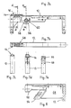
- Fig. 7a, 7b, 7c je eine Seitenansicht, Draufsicht bzw. Stirnansicht des Oberteils noch einer anderen Modul-Bauform,
- Fig. 7d und 7e je eine Schnittansicht entsprechend den Linien d-d bzw. e-e in Fig. 7a,
- Fig. 8 eine Teil-Schnittansicht entsprechend Fig. 7a mit eingesetzten Platinen,
- Fig. 9a, 9b, 9c je eine Seitenansicht, Draufsicht bzw. Stirnansicht eines Trägers für die Modul-Bauform entsprechend Fig. 7a, 7b, 7c,
- Fig. 9d eine Draufsicht des Trägers von Fig. 9a, 9b, 9c,
- Fig. 10a eine vergrößerte Draufsicht auf ein Ende des Trägers von Fig. 9b,
- Fig. 10b eine vergrößerte Stirnansicht entsprechend Fig. 9a, teilweise im Schnitt entsprechend der Linie b-b von Fig. 10a,
- Fig. 11 eine isolierte Drauf sicht auf eine Ebene eines Trägers, ähnlich der Druntersicht von Fig. 9d, und
- Fig. 12 einen Vertikalschnitt entsprechend der Linie a-a in Fig. 11.
- 1 is a sectional view of a module for an inventive device for displaying Braille,
- FIG. 2 shows a top view of the module from FIG. 1, with further indicated modules,
- 3 shows a sectional view of another module embodiment,
- 4 is a top view of the module of FIG. 3;
- 5 shows a sectional view of a further embodiment of a module according to the invention,
- 6 is a plan view, partly in section, of the module of FIG. 5,
- 7a, 7b, 7c each a side view, top view and end view of the upper part of another module design,
- 7d and 7e each a sectional view corresponding to the lines dd and ee in Fig. 7a,
- 8 is a partial sectional view corresponding to FIG. 7a with inserted boards,
- 9a, 9b, 9c each a side view, top view and end view of a carrier for the module design corresponding to FIGS. 7a, 7b, 7c,
- 9d is a top view of the carrier of FIGS. 9a, 9b, 9c,
- 10a is an enlarged top view of one end of the carrier of FIG. 9b,
- 10b is an enlarged front view corresponding to FIG. 9a, partially in section along the line bb of Fig. 10a,
- Fig. 11 is an isolated plan view of a plane of a carrier, similar to the bottom view of Fig. 9d, and
- 12 is a vertical section along the line aa in Fig. 11th
Das in Fig. 1 und 2 dargestellte, allgemein mit 10 bezeichnete Modul besteht aus einem Oberteil 12 und einem Träger 30, der - wie in Fig. 1 durch Doppelpfeil schematisch angedeutet - gegenüber dem Oberteil auf und ab beweglich ist. Dazu kann eine Stangenhalterung 46 vorgesehen sein, die von einer (nicht gezeichneten) Mechanik höhenveränderlich bewegbar ist.The module shown in FIGS. 1 and 2, generally designated 10, consists of an
Der Oberteil 12 hat eine Deckplatte 14, in der Fühlstifte 18 geführt sind, und zwar in zueinander parallelen Bohrungen. Die Fühlstifte 18 haben Kuppen 20, die in angehobener Stellung der Fühlstifte 18 die Außenfläche 16 tastbar überragen, jedoch in abgesenkter Stellung der Fühlstifte 18 in der Deckplatte 14 verschwinden.The
Die Fühlstifte 18 haben jeweils einen Flansch 22, an dem sich eine Druckfeder 24 abstützt, die den Fühlstift 18 im oberen Bereich umschließt und an der Innenfläche der Deckplatte 14 ihr Widerlager findet. Die Flansche 22 können an einer in die Deckplatte 14 unten eingelassenen Halterplatte 28 zur Auflage kommen.The feeler pins 18 each have a
Im unteren Bereich setzen sich die Fühlstifte 18 in vorgegebenen Längen fort. Ihre Bodenflächen 26 können auf Podesten 32 des Trägers 30 zur Anlage kommen. Dabei sind die Fühlstifte 18 in Buchsen 34 des Trägers 30 höhenbeweglich geführt. Soweit das Modul 10 so angeordnet ist, daß die Außenfläche 16 der Deckplatte 14 horizontal verläuft, stehen die darin angeordneten Führungsbohrungen für die Fühlstifte 18 und mithin diese selbst senkrecht. Dementsprechend sind auch die Buchsen 34 im Träger 30 vertikal angeordnet. Die Podeste 32 und die mit ihnen höhengleichen Kanäle bzw. Nuten 36 im Träger 30 verlaufen waagerecht, also quer zu den Fühlstiften 18.In the lower area, the feeler pins 18 continue in predetermined lengths. Their
In den Kanälen bzw. Nuten 36 befinden sich Magnetspulen 38, bevorzugt mit abwechselnd entgegengesetzter Polung. Im Inneren der Magnetspulen 38 sind Ankerstößel 40 axialbeweglich, die sich mit Federn 42 an einem Ende der Kanäle bzw. Nuten 36 abstützen, wo auch die Anschlüsse 52 der Magnetspulen 38 angeordnet sind. Die Federn 42 belasten die Ankerstößel 40 zu den jeweils zugeordneten Fühlstiften 18 hin.
Die Kanäle bzw. Nuten 36 im Träger 30 bilden eine treppenförmige Anordnung und sind so gestaffelt, daß jeder Ankerstößel bis in eine zugehörige Buchse 34 vordringen und darin seinen Anschlag finden kann. Wird nun der Träger 30 gegenüber dem Oberteil 12 abgesenkt, so kommen die Flansche 22 der Fühlstifte 18 an der Halteplatte 28 zur Anlage, während die Bodenfläche 26 der Fühlstifte 18 sich von der Stützfläche im Träger 30 abhebt. Bei genügender Absenkung schieben die Druckfedern 42 die Ankerstößel 40 nach vorn, d.h. jeweils unter die Bodenfläche 26 des zugehörigen Fühlstiftes 18. Bei anschließendem Anheben des Trägers 30 ragen dann sämtliche Fühlstifte 18 mit ihren Kuppen 20 über die Außenfläche 16 des Oberteils 12 vor. Sollen nur einzelne Fühlstifte 18 in dieser Weise gesetzt werden, so werden die übrigen dadurch in die abgesenkte Position gebracht, bei der die Bodenfläche 26 auf dem zugehörigen Podest 32 aufruht, daß die betreffenden Magnetspulen 38 erregt werden, wodurch die darin befindlichen Ankerstößel 40 entgegen der Kraft der Federn 42 zurückgezogen werden, wie in Fig. 1 für den untersten und den drittuntersten Ankerstößel 40 gezeigt. Dadurch kann sich beispielsweise ein Muster ergeben, wie in Fig. 2 im Zeichenfeld 48 der Außenfläche 16 schematisch dargestellt. Aus dieser Figur erkennt man zugleich, daß weitere Module 10 flächig an das erste Modul angeschlossen und mit ihm zu einem festen Block verbunden werden können, der das erfindungsgemäße Gerät bildet.The channels or
Auch bei der in Fig. 3 und 4 dargestellten Modul-Bauform ist ein Oberteil 12 des Moduls 10 ortsfest und ein darunter angeordneter Träger 30 vertikal beweglich, wie durch den Doppelpfeil in Fig. 3 angedeutet. Es finden wiederum zylindrische Fühlstifte 18 Verwendung, die im oberen Bereich unter federnder Abstützung in der Deckplatte 14 sowie in der Halteplatte 28 höhenbeweglich geführt sind. An letzterer können sich Flansche 22 der Fühlstifte 18 abstützen.3 and 4, an
Im Prinzip entspricht die Anordnung von Fig. 3 und 4 derjenigen von Fig. 1 und 2, doch liegen sich hier Magnetspulen 38 in Kanälen 36 des Trägers 30 auf gleicher Ebene gegenüber. Dementsprechend sind auch die zugeordneten Podeste 32 untereinander höhengleich. Man erkennt, daß man bei dieser Ausführungsform für ein Vierpunkt Zeichenfeld 48 (Fig. 4) mit je zwei Magnetpaaren beiderseits der vier Fühlstifte 18 auskommt. Im übrigen entspricht die Funktion der oben beschriebenen. Soll also ein Fühlstift 18 voll abgesenkt werden (in Fig. 3 links), so daß seine Bodenfläche 26 auf dem Podest 32 aufruht, so wird die betreffende Magnetspule 38 erregt und der Ankerstößel 40 dadurch entgegen Federkraft zurückgezogen. Ohne Erregung drückt jedoch die Druckfeder 42 den Ankerstößel 40 nach vorn, so daß er bis in die Buchse 34 hineinragt und dort anschlägt, vorausgesetzt, daß der Träger 30 vom Oberteil 12 genügend abgesenkt war. Wird der Träger 30 dann angehoben, so kommt die Bodenfläche 26 des betreffenden Fühlstiftes 18 auf dem vorderen Ende des vorgeschobenen Ankerstößels 40 zur Auflage, so daß der Stift angehoben wird und seine Kuppe 20 die Außenfläche 16 überragt.In principle, the arrangement of FIGS. 3 and 4 corresponds to that of FIGS. 1 and 2, but here
Man erkennt, daß die Anordnung von Fig. 3 und 4 zum Zeilenaufbau mit Vierpunkt-Zeichenfeldern 48 geeignet ist, während die Ausführungsform von Fig. 1 und 2 - bei etwas größerer Bauhöhe - zur Darstellung von Achtpunkt-Zeichen geeignet und vorgesehen ist (Fig. 2).It can be seen that the arrangement of FIGS. 3 and 4 is suitable for line construction with four-point character fields 48, while the embodiment of FIGS. 1 and 2 - with a somewhat greater overall height - is suitable and intended for the representation of eight-point characters (FIG. 2).
Allgemein entspricht die Bauform von Fig. 5 und 6 derjenigen von Fig. 3 und 4. Als Riegelelemente dienen hier jedoch piezokeramische Biegestreifen 50, die in den Kanälen 36 des Trägers 30 an den mit Anschlüssen 52 versehenen Enden festgelegt sind (Fig. 6). Im gezeichneten Beispiel liegt ein Biegestreifen 50 im Ruhezustand (rechts in Fig. 5 und 6) an einer inneren Trennwand des Trägers 30 an, und ein Fühlstift 18 stützt sich mit seiner Bodenfläche 26 auf dem freien Ende dieses Biegestreifens 50 ab, so daß der Fühlstift 18 angehoben ist und seine Kuppe 20 über die Außenfläche 16 des Oberteils 12 vorsteht. Wird nun elektrische Spannung angelegt, so entsteht der in Fig. 5 und 6 links dargestellte Zustand. Der Biegestreifen 50 biegt sich aus seiner Ebene heraus und schwenkt dadurch mit seinem freien Ende zur Seite, wodurch der betreffende Fühlstift 18 sich unter dem Druck seiner Feder 24 absenkt, bis der Flansch 22 an der Halteplatte 28 anschlägt.5 and 6 generally correspond to that of FIGS. 3 and 4. However, piezoceramic bending strips 50, which are fixed in the
Den beschriebenen Ausführungsformen ist gemeinsam, daß ein Halterand 44 des Oberteils 12 zu dessen Festlegung an einem (nicht gezeichneten) Gehäuse dienen kann.The described embodiments have in common that a holding
Die Fig. 7 bis 12 zeigen ein weiteres praktisches Ausführungsbeispiel von Modulen für ein erfindungsgemäßes Gerät. Zunächst ist in Fig. 7a bis 7e und Fig. 8 der Oberteil 12 dargestellt, dessen Deckplatte 14 hier etwas nach oben absteht, so daß die Außenfläche 16 mit dem Zeichenfeld 48 höher liegt als die übrigen Abschnitte des Oberteils 12. Dieser kann ein Kunststoff-Spritzteil mit Seitenwangen 56 sein, in denen eine Lagerbohrung 58 vorhanden ist. Zur Querverbindung einzelner Module 10 miteinander ist eine Anzahl von (nicht näher bezeichneten) kleinen Bohrungen vorgesehen, durch die eine Verschraubung, Verstiftung o.dgl. möglich ist. Ein freier Bereich des Oberteils 12 kann innen bzw. unten eine Leiterplatte 68 aufnehmen (Fig. 8), die zur Stromversorgung einer Steuerplatine 54 dient, welche am zugeordneten Träger 30 angebracht ist.7 to 12 show a further practical embodiment of modules for a device according to the invention. First of all, the
Ein solcher Träger 30 ist in Fig. 9a bis 9d dargestellt. Er hat in einem oberen Bereich eine Lagerausnehmung 62, in die eine als Exzenter dienende, einseitig mit einer Abflachung versehene Achse oder Welle 60 einsetzbar ist, wie in Fig. 7a und 9a mit schematischem Querschnitt angedeutet. Der Träger 30 kann dann um die Achse bzw. Welle 60 so weit bewegt werden, bis ein als Anschlag 66 ausgebildetes Ende am Oberteil 12 innen ankommt. In Anbetracht der geringen Stellwege, die für eine Absenkung oder Anhebung der Fühlstifte 18 benötigt werden, genügt eine geringe Verschwenkung des Trägers 30.Such a
Dieser ist an einem Vorderteil (Fig. 9a und 9b; 10a) treppenförmig gestaltet und mit Kanälen 36 versehen, die jeweils waagrecht und höhengleich mit einem Podest 32 verlaufen. Über letzterem ist jeweils eine Buchse 34 angeordnet, die das untere Ende des zugeordneten Fühlstiftes 18 führt und zweckmäßig nach oben konisch erweitert ist, um seine Beweglichkeit trotz der Winkeländerung des Trägers 30 zu sichern.This is designed in a step-like manner on a front part (FIGS. 9a and 9b; 10a) and is provided with
Am anderen Ende, d.h. unterhalb des Anschlags 66, hat der Träger 30 eine Ausnehmung für die mit ihm fest verbundene Steuerplatine 54 (Fig. 9a und Fig. 8). Von dieser können (nicht gezeichnete) flexible Leitungen zu der Leiterplatte 68 führen, die zur Stromversorgung vorgesehen ist.At the other end, ie below the
Während Fig. 10a und 10b vergrößert die Abstütz- und Führungsanordnung für die Fühlstifte 18 zeigen, geht aus Fig. 11 und 12 hervor, wie piezokeramische Biegestreifen 50, die in den Kanälen bzw. Nuten 36 des Trägers 30 hochkant angeordnet sind, die Ver- und Entriegelung bewirken. Oben in Fig. 11 und links in Fig. 12 ist ein Biegestreifen 50 dargestellt, der die Bodenfläche des in angehobener Stellung befindlichen Fühlstiftes 18 untergreift und abstützt. Dagegen zeigt die untere Hälfte von Fig. 11 und die rechte Hälfte von Fig. 12 eine Entriegelungsstellung, bei welcher der betreffende Fühlstift 18 abgesenkt ist, nachdem durch Spannungs-Beaufschlagung des zugehörigen Biegestreifens 50 dieser unter dem Fühlstift 18 zur Seite wegbewegt wurde.While FIGS. 10a and 10b show the support and guide arrangement for the feeler pins 18 on an enlarged scale, FIGS. 11 and 12 show how piezoceramic bending strips 50, which are arranged upright in the channels or
Man erkennt, daß das erfindungsgemäße Gerät bequem in der von Blinden häufig bevorzugten Weise gestaltet werden kann, wonach nur diejenigen Zeichen bzw. Punkte gesetzt werden, die auch sogleich eine Information vermitteln sollen, während die Lesefläche 16 im übrigen leer bleibt (so daß die Kuppen 20 der eingefahrenen Fühlstifte 18 nicht tastbar sind).It can be seen that the device according to the invention can be designed comfortably in the way often preferred by blind people, according to which only those signs or points are set which are also intended to immediately convey information, while the reading
Wesentliche Vorteile der Erfindung beruhen darauf, daß der Modulaufbau eine sehr einfache und somit preisgünstige Leseeinrichtung für Blinde schafft, die z.B. zum Anzeigen von Zahlen bei Uhren, Thermometern usw., aber auch für längere Texte nutzbar ist. Nach Wahl lassen sich Zeilen-Displays auch zum Drucken benutzen. Die Ansteuerung erfolgt elektronisch, bevorzugt über einen Mikroprozessor, wobei die Stromversorgung über ein Netzgerät oder auch mit Batteriespeisung erfolgen kann.Significant advantages of the invention are based on the fact that the module structure creates a very simple and therefore inexpensive reading device for blind people who e.g. for displaying numbers on clocks, thermometers etc., but also for longer texts. If desired, line displays can also be used for printing. The control takes place electronically, preferably via a microprocessor, and the power supply can take place via a power supply unit or also with battery supply.
Von Bedeutung ist insbesondere, daß für das Stellen der Tast- bzw. Fühlstifte 18 nur geringe Kräfte benötigt werden. Zum Heben und Senken wird der Träger 30 bewegt, der dank seiner speziellen Gestaltung in flacher Bauweise und mit kleinem Gewicht ausgeführt werden kann. Dabei verlaufen die Riegelelemente 38, 40; 50 quer zu den Fühlstiften 18, so daß deren Ver- und Entriegelung schnell und stabil vor sich geht. Insgesamt werden nur wenige Bauteile benötigt, die sich überdies zu Baugruppen beliebiger Größe oder Kleinheit zusammensetzen lassen.It is particularly important that only small forces are required to set the feeler or feeler pins 18. For lifting and lowering, the
Im ortsfesten Oberteil 12 kommen abgesenkte Fühlstifte 18 mit ihrem Flansch 22 an der Halteplatte 28 zur Anlage. Diese nimmt also die Druckkräfte der Federn 24 auf, wenn der Träger 30 nach unten abgehoben ist. Dann können die Riegelelemente 40, 50 praktisch belastungsfrei angesteuert und betätigt werden, kurz bevor der Träger 30 zum Setzen des gewünschten Musters wieder angehoben wird. Dieser Vorteil bleibt auch erhalten, wenn Fühlstifte 18 ohne Federbelastung benutzt werden, was etwa im Ausführungsbeispiel von Fig. 7 bis 12 ohne weiteres möglich ist, weil die Stifte unter ihrem Eigengewicht von selbst die jeweils tiefste Lage einnehmen.In the fixed
Sämtliche aus den Ansprüchen, der Beschreibung und der Zeichnung hervorgehenden Merkmale und Vorteile, einschließlich konstruktiver Einzelheiten, räumlicher Anordnungen und Verfahrensschritten, können sowohl für sich als auch in den verschiedensten Kombinationen erfindungswesentlich sein.All of the features and advantages arising from the claims, the description and the drawing, including constructive details, spatial arrangements and method steps, can be essential to the invention both individually and in the most varied of combinations.
- 10 Modul(e)10 module (s)
- 12 Oberteil12 top
- 14 Deckplatte14 cover plate
- 16 Außenfläche16 outer surface
- 18 Fühlstifte18 feelers
- 20 Kuppen20 crests
- 22 Flansch22 flange
- 24 Druckfedern24 compression springs
- 26 Bodenfläche26 floor area
- 28 Halteplatte28 holding plate
- 30 Träger30 carriers
- 32 Podest(e)32 pedestal (s)
- 34 Buchse(n)34 socket (s)
- 36 Kanäle / Nuten36 channels / grooves
- 38 Magnetspulen38 solenoids
- 40 Ankerstößel40 anchor lifters
- 42 Federn42 springs
- 44 Halterand44 holding edge
- 46 Stangenhalterung46 rod holder
- 48 Zeichenfeld48 character field
- 50 (piezokeramische) Biegestreifen50 (piezoceramic) bending strips
- 52 Anschlüsse52 connections
- 54 Steuerplatine54 control board
- 56 Seitenwangen56 sidewalls
- 58 Lagerbohrung58 bearing bore
- 60 Achse / Welle / Exzenter60 axis / shaft / eccentric
- 62 Lagerausnehmung62 bearing recess
- 64 Anlagefläche64 contact surface
- 66 Anschlag66 stop
- 68 Leiterplatte68 printed circuit board
Claims (27)
Applications Claiming Priority (2)
| Application Number | Priority Date | Filing Date | Title |
|---|---|---|---|
| DE8801823U | 1988-02-12 | ||
| DE8801823U DE8801823U1 (en) | 1988-02-12 | 1988-02-12 |
Publications (3)
| Publication Number | Publication Date |
|---|---|
| EP0328149A2 true EP0328149A2 (en) | 1989-08-16 |
| EP0328149A3 EP0328149A3 (en) | 1992-08-05 |
| EP0328149B1 EP0328149B1 (en) | 1994-11-09 |
Family
ID=6820612
Family Applications (1)
| Application Number | Title | Priority Date | Filing Date |
|---|---|---|---|
| EP89102377A Expired - Lifetime EP0328149B1 (en) | 1988-02-12 | 1989-02-11 | Device for the representation of braille writing |
Country Status (2)
| Country | Link |
|---|---|
| EP (1) | EP0328149B1 (en) |
| DE (2) | DE8801823U1 (en) |
Cited By (4)
| Publication number | Priority date | Publication date | Assignee | Title |
|---|---|---|---|---|
| CN101853592A (en) * | 2010-05-17 | 2010-10-06 | 南京信息职业技术学院 | Braille convex-concave point control structure and progressive full-page driving Braille display |
| CN104408994A (en) * | 2014-11-11 | 2015-03-11 | 浙江理工大学 | Delaminated electromagnetic braille alphabet display device and braille alphabet reader |
| CN111462592A (en) * | 2020-05-09 | 2020-07-28 | 长春大学 | Piezoelectric elastic sheet type braille point display device |
| CN111752408A (en) * | 2020-06-03 | 2020-10-09 | 清华大学 | Tactile display device |
Families Citing this family (1)
| Publication number | Priority date | Publication date | Assignee | Title |
|---|---|---|---|---|
| DE19746617A1 (en) * | 1997-10-22 | 1999-05-06 | Gunnar Matschulat | Device for displaying tactile information |
Citations (5)
| Publication number | Priority date | Publication date | Assignee | Title |
|---|---|---|---|---|
| FR2408879A1 (en) * | 1977-11-10 | 1979-06-08 | Cii Honeywell Bull | DEVICE FOR CONVERTING DIGITAL ELECTRIC SIGNALS REPRESENTATIVE OF CHARACTERS INTO A SELF-LOCKED POINT REPRESENTATION, OF THE BRAILLE TYPE FOR EXAMPLE |
| WO1980001012A1 (en) * | 1978-11-06 | 1980-05-15 | S Rose | Braille display reader |
| GB1595894A (en) * | 1977-11-18 | 1981-08-19 | Clark & Smith Ind Ltd | Display devices |
| EP0225395A1 (en) * | 1985-12-11 | 1987-06-16 | Deutsche Blindenstudienanstalt e.V. | Device for presenting graphic information |
| EP0237090A1 (en) * | 1986-02-24 | 1987-09-16 | F.J. Tieman B.V. | Tactile relief display device and method for manufacturing it |
-
1988
- 1988-02-12 DE DE8801823U patent/DE8801823U1/de not_active Expired
-
1989
- 1989-02-11 DE DE58908614T patent/DE58908614D1/en not_active Expired - Fee Related
- 1989-02-11 EP EP89102377A patent/EP0328149B1/en not_active Expired - Lifetime
Patent Citations (5)
| Publication number | Priority date | Publication date | Assignee | Title |
|---|---|---|---|---|
| FR2408879A1 (en) * | 1977-11-10 | 1979-06-08 | Cii Honeywell Bull | DEVICE FOR CONVERTING DIGITAL ELECTRIC SIGNALS REPRESENTATIVE OF CHARACTERS INTO A SELF-LOCKED POINT REPRESENTATION, OF THE BRAILLE TYPE FOR EXAMPLE |
| GB1595894A (en) * | 1977-11-18 | 1981-08-19 | Clark & Smith Ind Ltd | Display devices |
| WO1980001012A1 (en) * | 1978-11-06 | 1980-05-15 | S Rose | Braille display reader |
| EP0225395A1 (en) * | 1985-12-11 | 1987-06-16 | Deutsche Blindenstudienanstalt e.V. | Device for presenting graphic information |
| EP0237090A1 (en) * | 1986-02-24 | 1987-09-16 | F.J. Tieman B.V. | Tactile relief display device and method for manufacturing it |
Cited By (5)
| Publication number | Priority date | Publication date | Assignee | Title |
|---|---|---|---|---|
| CN101853592A (en) * | 2010-05-17 | 2010-10-06 | 南京信息职业技术学院 | Braille convex-concave point control structure and progressive full-page driving Braille display |
| CN104408994A (en) * | 2014-11-11 | 2015-03-11 | 浙江理工大学 | Delaminated electromagnetic braille alphabet display device and braille alphabet reader |
| CN104408994B (en) * | 2014-11-11 | 2017-01-11 | 浙江理工大学 | Delaminated electromagnetic braille alphabet display device and braille alphabet reader |
| CN111462592A (en) * | 2020-05-09 | 2020-07-28 | 长春大学 | Piezoelectric elastic sheet type braille point display device |
| CN111752408A (en) * | 2020-06-03 | 2020-10-09 | 清华大学 | Tactile display device |
Also Published As
| Publication number | Publication date |
|---|---|
| EP0328149A3 (en) | 1992-08-05 |
| DE8801823U1 (en) | 1989-03-09 |
| DE58908614D1 (en) | 1994-12-15 |
| EP0328149B1 (en) | 1994-11-09 |
Similar Documents
| Publication | Publication Date | Title |
|---|---|---|
| DE2630931A1 (en) | ELECTROMAGNETIC SPEED PRINT HEAD | |
| DE112018000955T5 (en) | Updatable Braille line | |
| DE1635848C3 (en) | Pattern device for circular knitting machines with rotating needle carriers | |
| DE2121886C2 (en) | Screen printing machine | |
| DE19844428B4 (en) | Test probe for a finger tester, a method for driving a test probe, finger tester for testing printed circuit boards and a method for testing printed circuit boards with a finger tester | |
| EP0328149B1 (en) | Device for the representation of braille writing | |
| DE4028390C2 (en) | Electromagnetic jacquard control device | |
| EP0149055A2 (en) | Device for the production of a tactile display area | |
| DE3929275C1 (en) | Tactile display unit for blind people - has groups of projecting pegs forming Braille symbols | |
| DE2812380A1 (en) | PRINTING MACHINE | |
| DE2123780C3 (en) | Map search device | |
| DE2734886C3 (en) | Bistable device for displaying at least one point of tactile information | |
| EP0082975A1 (en) | Display device | |
| DE966761C (en) | Switching device for marker-controlled machines | |
| DE2450650C3 (en) | Device for beating cards or paper ribbons for jacquard weaving machines | |
| DE2152361C3 (en) | Static punch card reader | |
| DE2707362C2 (en) | Bistable device for displaying at least one point of tactile information | |
| AT387293B (en) | Device for displaying Braille | |
| DE1058767B (en) | Electromagnetic matrix memory | |
| DE2501712A1 (en) | Table surface with retractable pins forming braille characters - pins held in retracted position by perpendicular locking bolts | |
| DE2754224A1 (en) | Electronic device adjusting and clearing alphanumerical characters - has solenoid windings each with tappet containing ferromagnetic material | |
| DE2012739A1 (en) | High-speed printer | |
| DE824120C (en) | Electromechanical storage device for punch card machines | |
| DE1436194C3 (en) | Sorting device for index cards provided with edge slots and a magnetizable area on one edge, as well as index cards therefor | |
| DE2720592A1 (en) | Electromagnet controlled tactile display - has braille symbols formed by axially moved pins which project beyond surface |
Legal Events
| Date | Code | Title | Description |
|---|---|---|---|
| PUAI | Public reference made under article 153(3) epc to a published international application that has entered the european phase |
Free format text: ORIGINAL CODE: 0009012 |
|
| AK | Designated contracting states |
Kind code of ref document: A2 Designated state(s): DE ES FR NL |
|
| PUAL | Search report despatched |
Free format text: ORIGINAL CODE: 0009013 |
|
| AK | Designated contracting states |
Kind code of ref document: A3 Designated state(s): DE ES FR NL |
|
| 17P | Request for examination filed |
Effective date: 19921024 |
|
| 17Q | First examination report despatched |
Effective date: 19930319 |
|
| RAP1 | Party data changed (applicant data changed or rights of an application transferred) |
Owner name: HOFFARTH, RAINER |
|
| GRAA | (expected) grant |
Free format text: ORIGINAL CODE: 0009210 |
|
| AK | Designated contracting states |
Kind code of ref document: B1 Designated state(s): DE ES FR NL |
|
| PG25 | Lapsed in a contracting state [announced via postgrant information from national office to epo] |
Ref country code: NL Effective date: 19941109 Ref country code: FR Effective date: 19941109 Ref country code: ES Free format text: THE PATENT HAS BEEN ANNULLED BY A DECISION OF A NATIONAL AUTHORITY Effective date: 19941109 |
|
| REF | Corresponds to: |
Ref document number: 58908614 Country of ref document: DE Date of ref document: 19941215 |
|
| EN | Fr: translation not filed | ||
| NLV1 | Nl: lapsed or annulled due to failure to fulfill the requirements of art. 29p and 29m of the patents act | ||
| PLBE | No opposition filed within time limit |
Free format text: ORIGINAL CODE: 0009261 |
|
| STAA | Information on the status of an ep patent application or granted ep patent |
Free format text: STATUS: NO OPPOSITION FILED WITHIN TIME LIMIT |
|
| 26N | No opposition filed | ||
| PGFP | Annual fee paid to national office [announced via postgrant information from national office to epo] |
Ref country code: DE Payment date: 19970419 Year of fee payment: 9 |
|
| PG25 | Lapsed in a contracting state [announced via postgrant information from national office to epo] |
Ref country code: DE Free format text: LAPSE BECAUSE OF NON-PAYMENT OF DUE FEES Effective date: 19981103 |