EP0328092A1 - Cooking apparatus - Google Patents
Cooking apparatus Download PDFInfo
- Publication number
- EP0328092A1 EP0328092A1 EP89102216A EP89102216A EP0328092A1 EP 0328092 A1 EP0328092 A1 EP 0328092A1 EP 89102216 A EP89102216 A EP 89102216A EP 89102216 A EP89102216 A EP 89102216A EP 0328092 A1 EP0328092 A1 EP 0328092A1
- Authority
- EP
- European Patent Office
- Prior art keywords
- metal detector
- cooking appliance
- appliance according
- cooking
- following
- Prior art date
- Legal status (The legal status is an assumption and is not a legal conclusion. Google has not performed a legal analysis and makes no representation as to the accuracy of the status listed.)
- Withdrawn
Links
Images
Classifications
-
- F—MECHANICAL ENGINEERING; LIGHTING; HEATING; WEAPONS; BLASTING
- F24—HEATING; RANGES; VENTILATING
- F24C—DOMESTIC STOVES OR RANGES ; DETAILS OF DOMESTIC STOVES OR RANGES, OF GENERAL APPLICATION
- F24C15/00—Details
- F24C15/10—Tops, e.g. hot plates; Rings
- F24C15/102—Tops, e.g. hot plates; Rings electrically heated
- F24C15/105—Constructive details concerning the regulation of the temperature
-
- H—ELECTRICITY
- H05—ELECTRIC TECHNIQUES NOT OTHERWISE PROVIDED FOR
- H05B—ELECTRIC HEATING; ELECTRIC LIGHT SOURCES NOT OTHERWISE PROVIDED FOR; CIRCUIT ARRANGEMENTS FOR ELECTRIC LIGHT SOURCES, IN GENERAL
- H05B3/00—Ohmic-resistance heating
- H05B3/68—Heating arrangements specially adapted for cooking plates or analogous hot-plates
- H05B3/74—Non-metallic plates, e.g. vitroceramic, ceramic or glassceramic hobs, also including power or control circuits
- H05B3/746—Protection, e.g. overheat cutoff, hot plate indicator
-
- H—ELECTRICITY
- H05—ELECTRIC TECHNIQUES NOT OTHERWISE PROVIDED FOR
- H05B—ELECTRIC HEATING; ELECTRIC LIGHT SOURCES NOT OTHERWISE PROVIDED FOR; CIRCUIT ARRANGEMENTS FOR ELECTRIC LIGHT SOURCES, IN GENERAL
- H05B2213/00—Aspects relating both to resistive heating and to induction heating, covered by H05B3/00 and H05B6/00
- H05B2213/05—Heating plates with pan detection means
Abstract
Description
Die Erfindung betrifft ein Kochgerät gemäß dem Oberbegriff des ersten Anspruchs.The invention relates to a cooking appliance according to the preamble of the first claim.
Bei einem bekannten Kochgerät dieser Art (FR-PS 13 92 763) ist unter einer als geschlossenes Kochfeld ausgebildeten Kochfläche eines Heizelements ein Metalldetektor als Sensor zur Erfassung des Vorhandenseins oder Fehlens eines Metallgefäßes angeordnet. Der Sensor ist an ein Steuerelement angeschlossen, das bei Vorhandensein eines Metallgefäßes im Kochbereich einen Stromkreis des Heizelementes schaltet, so daß nur dann das Heizelement an Spannung gelegt ist. Es zeigt sich, daß im praktischen Betrieb äußere Störeinflüsse das Schaltverhalten nachteilig beeinflussen können.In a known cooking device of this type (FR-PS 13 92 763), a metal detector is arranged as a sensor for detecting the presence or absence of a metal vessel under a cooking surface of a heating element designed as a closed hob. The sensor is connected to a control element which, in the presence of a metal vessel in the cooking area, switches a circuit of the heating element so that the heating element is only energized. It can be seen that external interference can adversely affect the switching behavior in practical operation.
Der Erfindung liegt die Aufgabe zugrunde, bei einem Kochgerät gemäß dem Oberbegriff des ersten Anspruchs Maßnahmen zu treffen, durch welche störende Einflüsse durch äußere, insbesondere elektromagnetische Felder vermindert oder ganz vermieden werden.The invention has for its object to take measures in a cooking appliance according to the preamble of the first claim, by means of which disruptive influences by external, in particular electromagnetic, fields are reduced or avoided entirely.
Die Lösung dieser Aufgabe erfolgt gemäß der Erfindung durch die kennzeichnenden Erfindungsmerkmale.This object is achieved according to the invention by the characterizing features of the invention.
Bei einem Aufbau eines Kochgerätes gemäß der Erfindung wird nicht nur eine Energieeinsparung dadurch erzielt, weil das Heizelement nur bei vorhandenem Gefäß eingeschaltet wird, vielmehr werden auch Störeinflüsse auf den Metalldetektor, bzw. von ihm ausgehende Störfelder durch die Abschirmschale minimiert. Daneben ist es zweckmäßig den Metallsensor durch das Steuerelement nur kurzzeitig, aber wiederholt zu aktivieren bzw. auf das Vorhandensein bzw. Fehlen des Gefäßes abzufragen und während dieser Aktivierungs- bzw. Abfragedauer auf jeden Fall das Heizelement auszuschalten, um Störungen durch davon erzeugte Magnetfelder zu vermeiden.In the construction of a cooking appliance according to the invention, not only is energy savings achieved because the heating element is only switched on when the vessel is present, but also interference from the metal detector or interference fields emanating from it are minimized by the shielding shell. In addition, it is expedient to activate the metal sensor by the control element only briefly, but repeatedly, or to check for the presence or absence of the vessel interrogate and switch off the heating element in any case during this activation or interrogation period in order to avoid interference from magnetic fields generated thereby.
Weitere vorteilhafte Ausgestaltungen der Erfindung sind in den Ansprüchen angegeben.Further advantageous embodiments of the invention are specified in the claims.
Die Erfindung ist nachfolgend anhand der Skizzen eines Ausführungsbeispiels näher erläutert.The invention is explained in more detail below with the aid of the sketches of an exemplary embodiment.
Es zeigen:
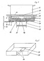
- - Fig. 1 eine einzelne Kochstelle eines Kochgerätes mit einer Heizeinrichtung und
- - Fig. 2 eine Abschirmschale für die Heizeinrichtung
- - Fig. 1 shows a single hotplate of a cooking device with a heating device and
- - Fig. 2 is a shielding shell for the heating device
Ein in einem Ausschnitt schematisch dargestellten Kochgerät weist eine nicht metallische, insbesondere glaskeramische Kochfläche 1 auf, die ohne Durchbrüche oder dergl. und plan ausgebildet ist. Mit Abstand unterhalb der Unterseite 2 der Kochfläche 1 befindet sich eine parallel dazu verlaufende unmagnetische Isolierstoffplatte 3, deren Außenränder topfförmig nach oben bis an die Unterseite 2 hochgezogen sind und die im übrigen eine elektrische Heizwendel 4 auf ihrer innenliegenden Oberseite 5 trägt. Die vom Heizelement 4 untergriffene Fläche bestimmt innerhalb der Kochfläche 1 einen Kochbereich, der im dargestellten Beispiel mit dem Boden 10 eines metallischen Gefäßes 6 etwa identisch ist. Das Vorhandensein oder Fehlen dieses Gefäßes 6 wird mittels eines Metalldetektors 7 festgestellt, der der Unterseite 11 der Isolierstoffplatte 3 benachbart angeordnet ist, dessen aktive Seite zum Kochbereich hinweist und der zudem außerhalb eines vom Heizelement 4 bedeckten Bereiches angeordnet ist.A cooking device shown schematically in a detail has a non-metallic, in particular glass-ceramic cooking surface 1, which is designed without openings or the like. At a distance below the
Der Metalldetektor 7 wirkt mit seinem Sensorfeld bis in den Kochbereich hinein und beeinflußt ein nicht gezeigtes Steuerelement in der Weise, daß bei vorhandenem Gefäß 6 bei sonst vorbereitetem Einschaltzustand das Heizelement 4 eingeschaltet und das Gefäß 6 beheizt wird. Fehlt das Gefäß, wird über den Metalldetektor 7 bei noch vorbereitetem Einschaltzustand der Stromkreis des Heizelementes 4 unterbrochen.The
Um Störungen, insbesondere von benachbarten und ähnlich aufgebauten Heizeinrichtungen zumindest weitgehend auszuschalten bzw. Störfelder nicht nach außen gelangen zu lassen, ist die gesamte Isolierstoffplatte 3 mit den hochgezogenen Außenrändern und dem Heizelement 4 in einer angepaßten, topfförmigen Abschirmschale 30 angeordnet, die im aktiven Bereich des Metalldetektors 7 einen angepaßten Ausschnitt 31 besitzt. Durch diesen Ausschnitt 31 tritt das Sensorfeld des Metalldetektors 7 zum Kochbereich hin durch die Isolierstoffplatte 3 und durch die Kochfläche 1 bis in den Bereich hindurch, auf den das Gefäß 6 aufzusetzen ist und detektiert werden kann. Die Abschirmschale 30 besteht vorzugsweise aus Chromnickelstahl- oder Aluminiumblech bzw. einem nichtmagnetischen Material. Der Metalldetektor 7 ist mittels eines temperaturbeständigen, dauerelastischen Klebers 32 an der Abschirmschale 30 festgesetzt, so daß Dehnungen zu keinen mechanischen Verspannungen führen können, die Fehlmessungen nach sich ziehen.In order to at least largely switch off faults, in particular from neighboring and similarly designed heating devices, or to prevent interference fields from reaching the outside, the entire
Dabei ist der Metallsensor7 durch den in dem Ausschnitt 31 gebildeten Luftspalt und durch den Kleber 32 thermisch von der Isolierstoffplatte 3 entkoppelt, die ihrerseits eine hochwertige Wärmedämmung mit einer Wärmeleitzahl von ca. 0,02 W/mk bildet, um am Metalldetektor 7 die Temperatur, die vom Heizelement 4 ausgeht, zur Vermeidung von Störungen möglichst niedrig zu halten. Um dennoch bei auftretenden, erhöhten Temperaturen ohne Störungen arbeiten zu können, weist der Metalldetektor 7 einen Schalenkern aus einem Ferrit mit hoher Curietemperatur sowie eine Wicklung aus einem Draht mit einer hochtemperaturfesten Isolierung auf. Außerdem kann der Metalldetektor 7 im Luftstrom eines Gebläses oder eines Konvektionsschachts angeordnet sein, um seine Temperatur möglichst gleich halten zu können. Der Luftstrom kann gesteuert sein in Abhängigkeit von der Temperatur des Metallsensors 7. Daneben ist dem Metalldetektor ein Heizwiderstand 33 zugeordnet, der thermostatisch gesteuert die Temperatur des Metallsensors 7 weitgehend konstant hält. Durch diese die Temperatur steuernden Mittel bleibt die Empfindlichkeit des Metalldetektors auch bei den verschiedenen, im Betrieb auftretenden störenden Temperaturen hinreichend gleich.The
Im übrigen ist die Abschirmschale 30 zu Verminderung von störenden Ringströmen, die durch das vom aktiven Bereich des Metalldetektors 7 ausgehende elektromagnetische Wechselfeld in der Abschirmschale 30 entstehen können,wenigstens mit einem Schlitz 34 versehen. Dieser Schlitz 34 reicht vorzugsweise ausgehend vom Ausschnitt 31 in radialer Richtung einseitig bis durch den hochgezogenen Rand (Fig. 2). Es können auch mehrere, nur Teillängen der Abschirmschale 30 aufweiende S
Schlitze vorgesehen werden. Durch das Schlitzen wird der Metalldetektor 7 weniger elektrisch bedämpft und daher seine Wirksamkeit erhöht.For the rest, the
Slots are provided. The
Werden mehrere derartige Heizeinrichtungen nebeneinander unter einer gemeinsamen Kochfläche 1 angeordnet, dann sind zweckmäßig zur Vermeidung von gegenseitigen Beeinflussungen die Abschirmschalen 30 gegeneinander sowie gegenüber einem gemeinsamen, nur angedeuteten Trägerrahmen 35 elektrisch isoliert. Diese maßnahme wird zweckmäßig auch zwischen dem Trägerrahmen 35 und einem ebenfalls nur angedeuteten Gerätegehäuse 36 angewandt.If several heating devices of this type are arranged next to one another under a common cooking surface 1, then the
Eine Möglichkeit zur Unterbindung von Störeinflüssen besteht auch darin, daß der Metalldetektor nur kurzzeitig, aber während der Dauer, in welcher durch manuell zu betätigende Schalteinrichtungen die Einschaltung einer Heizeinrichtung möglich bzw. vorbereitet ist, wiederholt impulsmäßig aktiviert wird oder elektrisch abgefragt wird. Dabei wird während der kurzzeitigen Aktivierung bzw. Abfrage des Metalldetektors 7 der Stromkreis des Heizelementes 3 in jedem Fall unterbrochen. Das Magnetfeld des Heizelementes 3 kann dann keine Fehlsteuerung verursachen. Dabei eignet sich der Impulsbetrieb des Metalldetektors 7 besonders bei mehreren Heizeinrichtungen, weil dann mit einem Steuerelement alle Metalldetektoren nacheinander aktiviert und/oder abgefragt werden können, ob ein metallisches Gefäß 6 auf dem zugehörigen Kochbereich aufgesetzt ist oder nicht.One possibility for preventing interference is that the metal detector is only activated briefly, or during the period in which the switching on of a heating device is possible or prepared, by manually operated switching devices, or is interrogated electrically. The circuit of the
Vorzugsweise ist jeder Heizeinrichtung ein Energieregler 39 oder Temperaturbegrenzer zugeschaltet, der den Stromkreis des jeweils zugeordneten Heizelementes 3 bei Erreichen vorgegebener Betriebsbedingungen unterbricht. Diese Unterbrechungen werden vorzugsweise dem Steuerelement mitgeteilt, das dann den zugehörigen Metalldetektor 7 aktiviert und/oder abfragt. Hierdurch werden Unterbrechungen des Stromkreises eingespart und zusätzliche Funkstörungen vermieden.Each heating device is preferably connected to an
Bei impulsmäßigem Betreiben des oder der Metalldetektoren 7 wird zwar bei Aufsetzen wie beim Abnehmen des Gefäßes 6 möglicherweise eine Verzögerung des Schaltvorganges eintreten, jedoch kann die Impulsfrequenz so hoch gewählt werden, daß keine merklichen Nachteile erwachsen. Im übrigen liegt die Unterbrechungsdauer des Stromkreises für das Heizelement 3 beispielsweise bei 0,5 Sekunden.If the metal detector (s) 7 is operated in pulsed mode, a delay in the switching process may occur when the
Schließlich ist es möglich, Maßnahmen zu treffen, daß die Justierung der Topferkennungseinrichtung automatisch erfolgt, derart, daß die Elektronik sich dann selbst justiert, wenn sie erkennt, daß kein Topf bzw. Gefäß aufgesetzt ist. Der Bereich, innerhalb welchem der Metalldetektor 7 ein aufgesetztes Gefäß 6 detektiert, ist in Fig. 1 mit 37 bezeichnet und liegt in einer Flucht mit dem Ausschnitt 31 sowie dem von Windungen des Heizelementes 4 freien Bereich 38 auf der Oberseite 5 der Isolierstoffplatte 3.Finally, it is possible to take measures that the adjustment of the pot detection device takes place automatically, in such a way that the electronics adjust themselves when they recognize that no pot or vessel has been placed. The area within which the
Claims (18)
Applications Claiming Priority (2)
| Application Number | Priority Date | Filing Date | Title |
|---|---|---|---|
| DE19883804170 DE3804170A1 (en) | 1987-04-06 | 1988-02-11 | Cooking apparatus |
| DE3804170 | 1988-02-11 |
Publications (1)
| Publication Number | Publication Date |
|---|---|
| EP0328092A1 true EP0328092A1 (en) | 1989-08-16 |
Family
ID=6347146
Family Applications (1)
| Application Number | Title | Priority Date | Filing Date |
|---|---|---|---|
| EP89102216A Withdrawn EP0328092A1 (en) | 1988-02-11 | 1989-02-09 | Cooking apparatus |
Country Status (1)
| Country | Link |
|---|---|
| EP (1) | EP0328092A1 (en) |
Cited By (1)
| Publication number | Priority date | Publication date | Assignee | Title |
|---|---|---|---|---|
| EP0429120A2 (en) * | 1989-11-17 | 1991-05-29 | Whirlpool Europe B.V. | Device for detecting the presence of a food cooking container on a cooking hob |
Citations (3)
| Publication number | Priority date | Publication date | Assignee | Title |
|---|---|---|---|---|
| FR1340411A (en) * | 1962-11-14 | 1963-10-18 | Hot plates | |
| US3796850A (en) * | 1973-05-31 | 1974-03-12 | Westinghouse Electric Corp | Pan detector for induction heating cooking unit |
| FR2259571A1 (en) * | 1974-02-04 | 1975-08-29 | Matsushita Electric Ind Co Ltd |
-
1989
- 1989-02-09 EP EP89102216A patent/EP0328092A1/en not_active Withdrawn
Patent Citations (3)
| Publication number | Priority date | Publication date | Assignee | Title |
|---|---|---|---|---|
| FR1340411A (en) * | 1962-11-14 | 1963-10-18 | Hot plates | |
| US3796850A (en) * | 1973-05-31 | 1974-03-12 | Westinghouse Electric Corp | Pan detector for induction heating cooking unit |
| FR2259571A1 (en) * | 1974-02-04 | 1975-08-29 | Matsushita Electric Ind Co Ltd |
Cited By (2)
| Publication number | Priority date | Publication date | Assignee | Title |
|---|---|---|---|---|
| EP0429120A2 (en) * | 1989-11-17 | 1991-05-29 | Whirlpool Europe B.V. | Device for detecting the presence of a food cooking container on a cooking hob |
| EP0429120A3 (en) * | 1989-11-17 | 1991-09-11 | Whirlpool International B.V. | Device for detecting the presence of a food cooking container on a cooking hob |
Similar Documents
| Publication | Publication Date | Title |
|---|---|---|
| EP0471171B1 (en) | Device for regulating and limiting the power of a heating plate of ceramic or similar material | |
| EP0438656B1 (en) | Cooking plate | |
| EP0788293B1 (en) | Electric radiant heater with active sensor for cooking vessel detection | |
| DE60028485T2 (en) | Object detection system which detects, for example, the presence of a metallic cooking utensil on a non-metallic cooking surface | |
| EP0467134B1 (en) | Method and apparatus for indicating an abnormal thermal load condition of a heating surface | |
| DE3744372C2 (en) | Power control method for protecting glass ceramic cooking surfaces | |
| DE4004129A1 (en) | DEVICE FOR RECOGNIZING A COOKING VESSEL SET UP IN A HEATING ZONE OF A COOKING OR HEATING APPLIANCE | |
| EP0951805B1 (en) | Cooktop with a non-metallic hotplate | |
| DE2653389C2 (en) | Hob | |
| DE3505233C1 (en) | Arrangement for controlling and regulating the heating power in the heating phase of a cooking vessel | |
| DE2329743A1 (en) | INDUCTION HEATING DEVICE, IN PARTICULAR AS A HOUSEHOLD STOVE | |
| EP0722261A1 (en) | Cooking heater with radiation hob and induction hob | |
| EP0374868A1 (en) | Cooking hob | |
| EP0116861B2 (en) | Electric radiant heating element for heating cooking or hot plates, especially glass ceramic plates | |
| DE3327622A1 (en) | Electrical hotplate for a glass-ceramic cooking plate | |
| DE10035745A1 (en) | Temperature detection device for an electric radiant heater | |
| DE19648397A1 (en) | Method and device for recognizing the cooking point of food | |
| EP0652688A1 (en) | Method of controlling the heating power of a vitroceramic hob according to required cooking conditions | |
| DE3711589C2 (en) | ||
| EP0967839A2 (en) | Cooking plate with operating unit determining its power level | |
| DE4413979C2 (en) | Sensor-controlled cooking unit and cooking device | |
| DE3533997C2 (en) | ||
| DE3804170A1 (en) | Cooking apparatus | |
| DE69836478T2 (en) | Purpose induction cooker | |
| EP3799527A1 (en) | Induction hob and method for controlling an induction hob |
Legal Events
| Date | Code | Title | Description |
|---|---|---|---|
| PUAI | Public reference made under article 153(3) epc to a published international application that has entered the european phase |
Free format text: ORIGINAL CODE: 0009012 |
|
| AK | Designated contracting states |
Kind code of ref document: A1 Designated state(s): AT CH DE ES FR GB IT LI NL |
|
| 17P | Request for examination filed |
Effective date: 19890831 |
|
| 17Q | First examination report despatched |
Effective date: 19900417 |
|
| STAA | Information on the status of an ep patent application or granted ep patent |
Free format text: STATUS: THE APPLICATION IS DEEMED TO BE WITHDRAWN |
|
| 18D | Application deemed to be withdrawn |
Effective date: 19910611 |