EP0328066A2 - Method of detecting noise disappearance and detecting device therefor - Google Patents
Method of detecting noise disappearance and detecting device therefor Download PDFInfo
- Publication number
- EP0328066A2 EP0328066A2 EP89102145A EP89102145A EP0328066A2 EP 0328066 A2 EP0328066 A2 EP 0328066A2 EP 89102145 A EP89102145 A EP 89102145A EP 89102145 A EP89102145 A EP 89102145A EP 0328066 A2 EP0328066 A2 EP 0328066A2
- Authority
- EP
- European Patent Office
- Prior art keywords
- value
- output
- output signal
- receiving
- threshold value
- Prior art date
- Legal status (The legal status is an assumption and is not a legal conclusion. Google has not performed a legal analysis and makes no representation as to the accuracy of the status listed.)
- Granted
Links
Images


Classifications
-
- G—PHYSICS
- G05—CONTROLLING; REGULATING
- G05B—CONTROL OR REGULATING SYSTEMS IN GENERAL; FUNCTIONAL ELEMENTS OF SUCH SYSTEMS; MONITORING OR TESTING ARRANGEMENTS FOR SUCH SYSTEMS OR ELEMENTS
- G05B23/00—Testing or monitoring of control systems or parts thereof
- G05B23/02—Electric testing or monitoring
- G05B23/0205—Electric testing or monitoring by means of a monitoring system capable of detecting and responding to faults
- G05B23/0218—Electric testing or monitoring by means of a monitoring system capable of detecting and responding to faults characterised by the fault detection method dealing with either existing or incipient faults
- G05B23/0224—Process history based detection method, e.g. whereby history implies the availability of large amounts of data
- G05B23/0227—Qualitative history assessment, whereby the type of data acted upon, e.g. waveforms, images or patterns, is not relevant, e.g. rule based assessment; if-then decisions
- G05B23/0232—Qualitative history assessment, whereby the type of data acted upon, e.g. waveforms, images or patterns, is not relevant, e.g. rule based assessment; if-then decisions based on qualitative trend analysis, e.g. system evolution
Definitions
- the present invention relates to a method of detecting a noise disappearance and a detecting device therefor, wherein output signals from a detector are received successively and a decreased noise component concerned with process vibrations and included in the output signal due to a fault of a plant (sticking of a valve, blocking of a piping, etc.) or a trouble in an instrument itself is detected, thereby detecting the fault of a plant or the trouble in the instrument itself.
- Fluctuations of the process is divided into two types.
- One type of fluctuations of the process including low frequency waves occurs in a case where the operating conditions of the process are changed or disturbances take place in the process. In this case, the value of the process changes relatively moderately.
- the stable operation is performed with no change being given to the process, if the liquid surface is shaken or pulsations in the flow rate occur due to the conveyance by a pump, then there occurs the other type of fluctuations of the process including high frequency waves such as noises.
- a differential pressure type level meter as being a detector provided in a plant detects a level of a liquid surface in a vessel.
- the above-described level meter and vessel are connected to each other through a conduit.
- output signal from the level meter falls into the state of no change when the interior of the conduit is blocked.
- the pressure in the conduit is varied with time due to the condensation and contraction of the vapor phase in the conduit, and, in many cases, the output signal from the detector continues the increase or decrease.
- the high frequency vibration components included in the output signal decrease, however, there has been presented the problem that the noise disappearance cannot be detected, in a state where the output signal shows the increase of decrease, by the conventional technique.
- the present invention has been developed to solve the above-described disadvantages of the prior art and has as its object the provision of a method of detecting noise disappearance and detecting device therefor wherein data subjected to the sampling successively are processed by a relatively easy technique, and, when a noise disappearance phenomenon is occured in detected output signals due to some abnormality or other, the phenomenon is quickly detected and an operator is notified of it.
- a method of detecting a noise disappearance is characterized by including the steps of: storing past values from a data collecting means for successively collecting output signals from a detector; processing by a processing means an absolute difference between the newest value collected by the data collecting means and a past value of a predetermined period of time before, which is successively renewed by the data storing means; receiving an output signal from the processing means, comparing it with a preset value, stepping up a count number of a counter means when the output value from the processing means is smaller than the preset value, and clearing the count number when the output value is larger than the preset value; and issuing a predetermined alarm when the count number exceeds a preset threshold value and detecting the disappearance of a noise component even if the output signal from the detector fluctuates.
- a method of detecting a noise disappearance is characterized by including the steps of: storing past values from a data collecting means for successively collecting output signals from a detector; processing by a processing means an absolute difference between the newest value collected by the data collecting means and a past value stored in the data storing means; receiving an output signal from the processing means, comparing it with a preset value, stepping up a count number of a counter means when the output value from the processing means is smaller than the preset value, and clearing the count number when the output value is larger than the preset value; issuing a predetermined alarm when the count number exceeds a preset threshold value and detecting the disappearance of a noise component; and receiving a threshold value renewing request signal given as necessary, and outputting the maximum value of the counter outputs during a predetermined period of time upon receiving the threshold value renewing request signal as the threshold value.
- Detecting device for detecting a noise disappearance comprises: data collecting means for successively collecting output signals from a detector; data storing means for storing past values of the detected values collected by the data collecting means; processing means for processing and outputting an absolute difference between the newest value collected by the data collecting means and a past value of a predetermined period of time before, which is stored in the data storing means and successively renewed; counter means for receiving an output signal from the processing means, comparing it with a preset value, stepping up a count number when the output value from the processing means is smaller than the preset value, and clearing the count number when the output value is larger than the preset value; limiter means for receiving an output signal from the counter means and outputting a trigger signal when the output signal exceeds a preset threshold value; and notifying means for receiving an output signal from the limiter means and issuing an alarm when the trigger signal is received; whereby, even when the output signal of the detected values fluctu
- detecting device for detecting a noise disappearance comprises: data collecting means for successively collecting output signals from a detector; data storing means for storing past values of the detected values collected by the data collecting means; processing means for constantly receiving the newest value collected by the data collecting means and the past value stored in the data storing means and processing and outputting an absolute difference between the both values; counter means for receiving an output signal from the processing means, comparing it with a preset value, stepping up a count number when the output value from the processing means is smaller than the preset value, and clearing the count number when the output value is larger than the preset value; limiter means for receiving an output signal from the counter means and outputting a trigger signal when the output signal exceeds a preset threshold value; notifying means for receiving an output signal from the limiter means and issuing an alarm when the trigger signal is received; and a threshold value renewing means for receiving a threshold value renewing request signal given as necessary and outputs
- the threshold value renewing means receives the outputs from the counter means and the threshold value renewing request signal given as necessary, and the maximum value of the counter outputs during a predetermined period of time upon receiving this threshold value renewing request signal is output into the limiter means as a new threshold value of the limiter means.
- a normal range can be empirically determined by taking in data in association with the characteristics of the respective detectors and changes in the operating conditions, etc.
- the magnitude of fluctuation of the detection signal and the threshold value of the count number are in interrelations in which the both parameters have the respective degrees of freedom, if one of the parameters is set, when the other can be determined accordingly. This requires to examine what kind of result follows in the case where one of the parameters is determined, and thereafter, the other is changed. According to the present invention, the above-described process can be easily performed and it becomes possible to determine the suitable values of the two parameters. In other words, unsuitable setting of the parameters which contributes to mistaken alarm information and time delay in the alarm giving can be avoided.
- the term "noise disappearance" in this specification refers to a case where the intrinsic high frequency vibration component included in the fluctuation, etc. of the process is decreased to considerable extent.
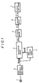
- output signal from by a detector 1 is successively collected by data collecting means 2 whose output signals are successively input into data storing means 3 and stored therein as being past value data which is to be output to processing means 4.
- the processing means 4 receives the output signal from the data collecting means 2 as the newest value (Snew) of the detector 1, receives an output signal from the data storing means 3 as a preceding time value (Sold) of the detector 1, the preceding time value being used as the past value obtained a predetermined period of time before, which is stored in and successively renewed by the data storing means 3, successively performs the calculation of an absolute difference as shown in the following equation (1) at each data collection time, and outputs the result (A) into counter means 5.
- A
- Limiter means 6 receives an output signal (C) from the counter means 5 and compares the output signal with a preset value (Cset) (a period of time, by which noise disappearance can be decided, is set). When the output signal (C) of the counter means 5 exceeds (Cset), a trigger signal (T) is turned “ON”. When the output signal (C) of the counter means 5 is smaller than (Cset), the trigger signal (T) if turned “OFF”. When the trigger output signal (T) of the limitter means 6 is "ON", notifying means 7 notifies the operator of the result, i.e. a occurrance of noise disappearance phenomenon by means of a CRT, a printer, an annunciator or the like.
- Cset a preset value
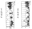
- Figs. 2(A) through 2(D) show examples of the output signals having various arrangements as shown in Fig. 1.
- Fig. 2 (A) shows an example of the output signal (Snew) from the data collecting means 2, corresponding to the fluctuation with time of output signal of the detector 1.
- 1 of Fig. 2(B) shows an example of the output signal (A) from the processing means 4, which is obtained by the absolute difference between the newest value from the data collecting means 2 and the proceeding time value from the data storing means 3 which is successively renewed, to the output signal of the detector 1 shown in Fig. 2(A), 2 of Fig. 2(B) an example of a preset value (Aset) of the counter means 5.
- 1 of Fig. 2(C) shows an example of the output signal (C) of the counter means 5, when the input signal of the counter means 5 which is output signal 1 of Fig.
- Fig. 2(B) becomes smaller than the preset value
- 2 of Fig. 2(C) an example of the threshold value (Cset) of the limiter means 6
- Fig. 2(D) an example of the trigger output signal (T) of the limiter menns 6, when the counter number as shown in Fig. 2(C) exceeds the threshold value.
- the trigger signal (T) is output into the notifying means 7 by the limiter means 6, to thereby notify the operator of the occurance of noise disappearance phenomena.
- the trigger signal (T) is turned off and the alarm is released.
- the absolute difference between the preceding time value and the newest time value of the detected values is calculated by the processing means 4 and it is decided whether the absolute difference is larger than the preset value or not, so that, even if only noise coomponent of the detected value signal having a tendency of increasing or decreasing in the regions ⁇ , ⁇ and ⁇ shown in Fig. 2(A) is descreased, the detection of it can be made in high accuracy.
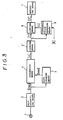
- this embodiment features in that there is additionally provided threshold value renewing means 8 which receives the output from the counter means 5 and a threshold value renewal request signal (R), and outputs a threshold renewed value (u) to the limiter means 6.
- the threshold value of the limiter means 6 is determined based on the threshold value renewal request signal (R) to the threshold value renewing means 8 such that the integrated value of the counter means 5 is statistically observed over a relatively long period of time and the threshold value is determined on the basis of the maximum value, so that such a meritorious effect can be added that a noise disappearance detecting device having higher reliability is obtained.
- the arrangement wherein the absolute difference between the newest value and the past value to be renewed successively, of the detected values, is calcurated and compared with the preset value.
- a reset signal is output from the processing means 4 to the data storing means 3, a detected value from the data collecting means 2, which is given to the data storing means 3 when this reset signal is received, is stored and renewed as a past value, and output to the processing means 4.
- the present invention can provide the method of detecting a noise disappearance and the detecting device therefor, wherein a noise disappearance phenomenon can be detected by relatively simple processing.
- the normal range can be empirically determined by taking in data in association with the characteristics of the respective detectors and the changes in the operating conditions, etc. Further, on the basis of the interrelations between the magnitudes of fluctuations of the detection signals and the threshold values of the count numbers, it becomes possible to examine what kind of result follows when one of the parameters is determined, and thereafter, the other is changed.
- this method of detecting a noise disappearance and the detecting device therefor adopt a simple logic, the logic can be included in a computer assembled in the plant, monitoring of the noise disappearance of the detection values in a large quantity can be performed without requiring so much load of the computer, and a period of time for observing detection values necessary for determining the noise disappearance can be automatically determined.
Landscapes
- Physics & Mathematics (AREA)
- General Physics & Mathematics (AREA)
- Engineering & Computer Science (AREA)
- Automation & Control Theory (AREA)
- Measurement Of Mechanical Vibrations Or Ultrasonic Waves (AREA)
Abstract
Description
- The present invention relates to a method of detecting a noise disappearance and a detecting device therefor, wherein output signals from a detector are received successively and a decreased noise component concerned with process vibrations and included in the output signal due to a fault of a plant (sticking of a valve, blocking of a piping, etc.) or a trouble in an instrument itself is detected, thereby detecting the fault of a plant or the trouble in the instrument itself.
- It has heretofore been difficult to detect a fault of the plant or the instruments at an early stage because, in most cases, operators did not sense the fault of the instruments, etc. until serious faults occur in a process. Particularly, after adoption of the DCS instrumentation, it has become difficult to grasp changed with time of detected values only by digital values, and further, to detect the fault. In addition, it is difficult to provide a device exclusively used for sensing the fault from the viewpoint of economics.
- Therefore, there has been proposed a device for detecting almost no change in output signal from detector provided in a plant, and giving a predetermined alarm as occurrence of a fault in the plant or the detector.
- As shown in Fig. 4 for example, in this device, even if the output signals fall into a preset abnormality determining value range having an upper and a lower limits (between HL and LL), the fact that the output value continue to be hardly changed is determined to be an abnormality by a determining system in which a difference of the output value from a certain reference value becomes continuously small.
- However, when the modes of abnormality occurrence in the plant due to faults of the detectors, blocking of the piping and the like are taken into consideration, it is not sufficient to merely monitor the state of no change in the output signal from the detector as in the conventional techniques. More specifically, with actual abnormalities, there are many cases where even if output signal itself of the detector fluctuates in tendency of increasing or decreasing, noise components which should be intrisically included in the fluctuation of signal decrease due to the abnormality, there is unavoidable the problem that the abnormality described above cannot be detected by the conventional technique. This is because the reference value during the occurrence of the abnormality is used in a fixed manner, that is, a detected value is merely compared with the reference value which is not renewed.
- Fluctuations of the process is divided into two types. One type of fluctuations of the process including low frequency waves occurs in a case where the operating conditions of the process are changed or disturbances take place in the process. In this case, the value of the process changes relatively moderately. On the other hand, even when the stable operation is performed with no change being given to the process, if the liquid surface is shaken or pulsations in the flow rate occur due to the conveyance by a pump, then there occurs the other type of fluctuations of the process including high frequency waves such as noises.
- When the latter fluctuations are observed, it may be said that the output value is normal. Accordingly, in order to perform the noise disappearance detecting with high accuracy, it is desirable that the former low frequency fluctuations and the latter high frequency fluctuations can be monitored separately from each other.
- To state further concretely, for example, assumption is made that a differential pressure type level meter as being a detector provided in a plant detects a level of a liquid surface in a vessel. The above-described level meter and vessel are connected to each other through a conduit.
- In general, it is easily considered that output signal from the level meter falls into the state of no change when the interior of the conduit is blocked. In practice, the pressure in the conduit is varied with time due to the condensation and contraction of the vapor phase in the conduit, and, in many cases, the output signal from the detector continues the increase or decrease. And yet, even in these cases, the high frequency vibration components included in the output signal decrease, however, there has been presented the problem that the noise disappearance cannot be detected, in a state where the output signal shows the increase of decrease, by the conventional technique.
- Therefore, the present invention has been developed to solve the above-described disadvantages of the prior art and has as its object the provision of a method of detecting noise disappearance and detecting device therefor wherein data subjected to the sampling successively are processed by a relatively easy technique, and, when a noise disappearance phenomenon is occured in detected output signals due to some abnormality or other, the phenomenon is quickly detected and an operator is notified of it.
- To achieve the above-described object, a method of detecting a noise disappearance according to a first aspect of the present invention is characterized by including the steps of:
storing past values from a data collecting means for successively collecting output signals from a detector;
processing by a processing means an absolute difference between the newest value collected by the data collecting means and a past value of a predetermined period of time before, which is successively renewed by the data storing means;
receiving an output signal from the processing means, comparing it with a preset value, stepping up a count number of a counter means when the output value from the processing means is smaller than the preset value, and clearing the count number when the output value is larger than the preset value; and
issuing a predetermined alarm when the count number exceeds a preset threshold value and detecting the disappearance of a noise component even if the output signal from the detector fluctuates. - Furthermore, a method of detecting a noise disappearance according to a second aspect of the present invention is characterized by including the steps of:
storing past values from a data collecting means for successively collecting output signals from a detector;
processing by a processing means an absolute difference between the newest value collected by the data collecting means and a past value stored in the data storing means;
receiving an output signal from the processing means, comparing it with a preset value, stepping up a count number of a counter means when the output value from the processing means is smaller than the preset value, and clearing the count number when the output value is larger than the preset value;
issuing a predetermined alarm when the count number exceeds a preset threshold value and detecting the disappearance of a noise component; and
receiving a threshold value renewing request signal given as necessary, and outputting the maximum value of the counter outputs during a predetermined period of time upon receiving the threshold value renewing request signal as the threshold value. - Detecting device for detecting a noise disappearance according to a third aspect of the invention, which conducts the method according to the first aspect of the invention, comprises:
data collecting means for successively collecting output signals from a detector;
data storing means for storing past values of the detected values collected by the data collecting means;
processing means for processing and outputting an absolute difference between the newest value collected by the data collecting means and a past value of a predetermined period of time before, which is stored in the data storing means and successively renewed;
counter means for receiving an output signal from the processing means, comparing it with a preset value, stepping up a count number when the output value from the processing means is smaller than the preset value, and clearing the count number when the output value is larger than the preset value;
limiter means for receiving an output signal from the counter means and outputting a trigger signal when the output signal exceeds a preset threshold value; and
notifying means for receiving an output signal from the limiter means and issuing an alarm when the trigger signal is received; whereby, even when the output signal of the detected values fluctuate, disappearance of the noise component is detected. - Furthermore, detecting device for detecting a noise disappearance according to a fourth aspect of the present invention which conducts the method according to the second aspect of the invention, comprises:
data collecting means for successively collecting output signals from a detector;
data storing means for storing past values of the detected values collected by the data collecting means;
processing means for constantly receiving the newest value collected by the data collecting means and the past value stored in the data storing means and processing and outputting an absolute difference between the both values;
counter means for receiving an output signal from the processing means, comparing it with a preset value, stepping up a count number when the output value from the processing means is smaller than the preset value, and clearing the count number when the output value is larger than the preset value;
limiter means for receiving an output signal from the counter means and outputting a trigger signal when the output signal exceeds a preset threshold value;
notifying means for receiving an output signal from the limiter means and issuing an alarm when the trigger signal is received; and
a threshold value renewing means for receiving a threshold value renewing request signal given as necessary and outputs from the counter means, and outputting to the limiter means the maximum value of the outputs from the counter means as a threshold value of the limiter means during a predetermined period of time upon receiving the threshold value renewing request signal. - With the above-described arrangements according to the present invention, when a noise disappearance phenomenon due to an abnormality in the plant or a fault in the detector itself, an absolute difference between the newest value and the past value of a predetermined period of time before of the detected values is processed and output, and, when the time during which the value of the absolute difference is continuously smaller than the preset value becomes larger than the preset time which has been determined to be abnormal, this situation is regarded as occurrence of a noise disappearance phenomenon and the operator can be notified of it.
- Furthermore, simultaneously with the above-described action, the threshold value renewing means receives the outputs from the counter means and the threshold value renewing request signal given as necessary, and the maximum value of the counter outputs during a predetermined period of time upon receiving this threshold value renewing request signal is output into the limiter means as a new threshold value of the limiter means.
- In detecting the noise disappearance, in order to detect it as quickly as possible, it is necessary to lessen the threshold value of the aforesaid count number. In this case, on the contrary, this may result in a factor causing occurrence of mistaken alarm information. On the other hand, it is very difficult to previously set a threshold value for determining an abnormality. According to the present invention, in setting the threshold value, a normal range can be empirically determined by taking in data in association with the characteristics of the respective detectors and changes in the operating conditions, etc.
- Further, since the magnitude of fluctuation of the detection signal and the threshold value of the count number are in interrelations in which the both parameters have the respective degrees of freedom, if one of the parameters is set, when the other can be determined accordingly. This requires to examine what kind of result follows in the case where one of the parameters is determined, and thereafter, the other is changed. According to the present invention, the above-described process can be easily performed and it becomes possible to determine the suitable values of the two parameters. In other words, unsuitable setting of the parameters which contributes to mistaken alarm information and time delay in the alarm giving can be avoided.
- Incidentally, the term "noise disappearance" in this specification refers to a case where the intrinsic high frequency vibration component included in the fluctuation, etc. of the process is decreased to considerable extent.
-
- Fig. 1 is a block diagram of the noise disappearance detecting device showing one embodiment to which the method according to the first aspect of the present invention is applied;
- Figs. 2(A) through 2(D) are charts showing the output signals in various sections of the device shown in Fig. 1;
- Fig. 3 is a block diagram of the noise disappearance detecting device showing one embodiment to which the method according to the second aspect of the present invention is applied; and
- Fig. 4 is a chart for explaining the conventional example.
- Embodiments of the present invention will hereunder be described with reference to the accompanying drawings.
- In. Fig. 1 showing one embodiment to which the method according to the first aspect of the invention is applied, output signal from by a
detector 1 is successively collected by data collecting means 2 whose output signals are successively input into data storing means 3 and stored therein as being past value data which is to be output to processing means 4. The processing means 4 receives the output signal from the data collecting means 2 as the newest value (Snew) of thedetector 1, receives an output signal from the data storing means 3 as a preceding time value (Sold) of thedetector 1, the preceding time value being used as the past value obtained a predetermined period of time before, which is stored in and successively renewed by the data storing means 3, successively performs the calculation of an absolute difference as shown in the following equation (1) at each data collection time, and outputs the result (A) into counter means 5.
A = |Snew - Sold| (1) - The counter means 5 receives an output signal from the processing means 4 and compares the output signal with a preset value (Aset) (a value, which is smaller than the vibrations of a normal signal, is set). When the output signal from the processing means 4 is not larger than the preset value, count number (C) of the counter means 5 is added. When the output signal of the processing means 4 is larger than the preset value, the count number (C) of the
counter 5 is cleared. Namely,
When A < Aset, C = Cold + 1 2(a)
When A ≧ Aset, C = 0 2(b)
- Limiter means 6 receives an output signal (C) from the counter means 5 and compares the output signal with a preset value (Cset) (a period of time, by which noise disappearance can be decided, is set). When the output signal (C) of the counter means 5 exceeds (Cset), a trigger signal (T) is turned "ON". When the output signal (C) of the counter means 5 is smaller than (Cset), the trigger signal (T) if turned "OFF". When the trigger output signal (T) of the limitter means 6 is "ON", notifying
means 7 notifies the operator of the result, i.e. a occurrance of noise disappearance phenomenon by means of a CRT, a printer, an annunciator or the like. - Figs. 2(A) through 2(D) show examples of the output signals having various arrangements as shown in Fig. 1.
- Fig. 2 (A) shows an example of the output signal (Snew) from the data collecting means 2, corresponding to the fluctuation with time of output signal of the
detector 1. ① of Fig. 2(B) shows an example of the output signal (A) from the processing means 4, which is obtained by the absolute difference between the newest value from the data collecting means 2 and the proceding time value from the data storing means 3 which is successively renewed, to the output signal of thedetector 1 shown in Fig. 2(A), ② of Fig. 2(B) an example of a preset value (Aset) of the counter means 5. ① of Fig. 2(C) shows an example of the output signal (C) of the counter means 5, when the input signal of the counter means 5 which isoutput signal ① of Fig. 2(B) becomes smaller than the preset value, ② of Fig. 2(C) an example of the threshold value (Cset) of the limiter means 6, and Fig. 2(D) an example of the trigger output signal (T) of thelimiter menns 6, when the counter number as shown in Fig. 2(C) exceeds the threshold value. - Now, as shown in Fig. 2(A), description will hereunder be given of a case where the noise disappearance phenomena occur at three positions α, β and γ in the drawing.
- During the normal period of time other than α, β and γ, and absolute difference (A) between the present time value and the preceding time value, which are the output signals from the processing means 4, is larger than the preset value (Aset), whereby the output (C) from the counter means 5 is small and does not exceed the preset value (Cset). However, during the periods of α, β and γ in Fig. 2(A) where the noise disappearance phenomena occur, the absolute difference (A) between the newest time value and the preceding time value, which are the output signals from the processing means 4, becomes sufficiently smaller than the preset value (Aset), whereby the output (C) from the counter means 5 increases and exceeds the threshold value (Cset). Then, the trigger signal (T) is output into the notifying
means 7 by the limiter means 6, to thereby notify the operator of the occurance of noise disappearance phenomena. Incidentally, when the output signals from thedetector 1 return to the normal conditions, the trigger signal (T) is turned off and the alarm is released. - According to the embodiment as described above, such an arrangement is adopted that the absolute difference between the preceding time value and the newest time value of the detected values is calculated by the processing means 4 and it is decided whether the absolute difference is larger than the preset value or not, so that, even if only noise coomponent of the detected value signal having a tendency of increasing or decreasing in the regions α, β and γ shown in Fig. 2(A) is descreased, the detection of it can be made in high accuracy.
- Another embodiment to which the method according to the second aspect of the invention is applied will be described with reference to Fig. 3. In this description, same reference numerals are used to designate to same parts corresponding to ones as in the embodiment described above, so that the description will be omitted or simplified.
- As shown in Fig. 3, this embodiment features in that there is additionally provided threshold value renewing means 8 which receives the output from the counter means 5 and a threshold value renewal request signal (R), and outputs a threshold renewed value (u) to the limiter means 6.
- With the above-described arrangement,
- (1) the threshold value renewal request signal (R) given as necessary in a case where the operating condition is changed, i.e. a calculation start signal for renewing a threshold value and the output from the counter means 5 are input into the threshold value renewing means 8. Upon receiving the threshold value renewal request signal (R), the threshold value renewing means 8, after collecting the outputs from the counter means 5 during a predetermined period of time, searches the maximum value, i.e. new threshold renewed value (u) and outputs the same into the limiter means 6.
- (2) On the other hand, the limiter means 6 acts similarly to the first embodiment until the time at which the threshold value renewal indication signal (R) is input. Thereafter, the limiter means 6 receives the threshold renewed value (u) as a new threshold value, decides an occurance of noise disappearance phenomena when the output value from the counter means 5 exceeds the renewed threshold value (u), and outputs the trigger signal (T) to the notifying
means 7. - According to the this embodiment as described above, the threshold value of the limiter means 6 is determined based on the threshold value renewal request signal (R) to the threshold value renewing means 8 such that the integrated value of the counter means 5 is statistically observed over a relatively long period of time and the threshold value is determined on the basis of the maximum value, so that such a meritorious effect can be added that a noise disappearance detecting device having higher reliability is obtained.
- Incidentally, in the example of working the method according to the second aspect of the present invention and the detecting device therefor, the arrangement wherein the absolute difference between the newest value and the past value to be renewed successively, of the detected values, is calcurated and compared with the preset value. However, in place of the above, such an arrangement may be adopted that, as for the past value, which is output from the data storing means 3 to the processing means 4, when the absolute value between the newest value and the past value in the processing means 4 exceeds the preset value, a reset signal is output from the processing means 4 to the data storing means 3, a detected value from the data collecting means 2, which is given to the data storing means 3 when this reset signal is received, is stored and renewed as a past value, and output to the processing means 4.
- As has been described hereinabove, the present invention can provide the method of detecting a noise disappearance and the detecting device therefor, wherein a noise disappearance phenomenon can be detected by relatively simple processing. Furthermore, in setting the threshold value, the normal range can be empirically determined by taking in data in association with the characteristics of the respective detectors and the changes in the operating conditions, etc. Further, on the basis of the interrelations between the magnitudes of fluctuations of the detection signals and the threshold values of the count numbers, it becomes possible to examine what kind of result follows when one of the parameters is determined, and thereafter, the other is changed. Since this method of detecting a noise disappearance and the detecting device therefor adopt a simple logic, the logic can be included in a computer assembled in the plant, monitoring of the noise disappearance of the detection values in a large quantity can be performed without requiring so much load of the computer, and a period of time for observing detection values necessary for determining the noise disappearance can be automatically determined.
Claims (4)
storing past values from a data collecting means for successively collecting output signals from a detector;
processing by a processing means an absolute difference between the newest value collected by the data collecting means and a past value of a predetermined period of time before, which is successively renewed by the data storing means;
receiving an output signal from the processing means, comparing it with a preset value, stepping up a count number of a counter means when the output value from the processing means is smaller than the preset value, and clearing the count number when the output value is larger than the preset value; and
issuing a predetermined alarm when the count number exceeds a preset threshold value and detecting the disappearance of a noise component even if the output signal from the detector fluctuates.
storing past values from a data collecting means for successively collecting output signals from a detector;
processing by a processing means an absolute difference between the newest value collected by the data collecting means and a past value stored in the data storing means;
receiving an output signal from the processing means, comparing it with a preset value, stepping up a count number of a counter means when the output value from the processing means is smaller than the preset value, and clearing the count number when the output value is larger than the preset value;
issuing a predetermined alarm when the count number exceeds a preset threshold value and detecting the disappearance of a noise component; and
receiving a threshold value renewing request signal given as necessary, and outputting the maximum value of the counter outputs during a predetermined period of time upon receiving the threshold value renewing request signal as the threshold value.
data collecting means for successively collecting output signals from a detector;
data storing means for storing past values of the detected values collected by the data collecting means;
processing means for processing and outputting an absolute difference between the newest value collected by the data collecting means and a past value of a predetermined period of time before, which is stored in the data storing means and successively renewed;
counter means for receiving an output signal from the processing means, comparing it with a preset value, stepping up a count number when the output value from the processing means is smaller than the preset value, and clearing the count number when the output value is larger than the preset value;
limiter means for receiving an output signal from the counter means and outputting a trigger signal when the output signal exceeds a preset threshold value; and
notifying means for receiving an output signal from the limiter means and issuing an alarm when the trigger signal is received;
whereby, even when the output signal of the detected values fluctuates, disappearance of the noise component is detected.
data collecting means for successively collecting output signals from a detector;
data storing means for storing past values of the detected values collected by the data collecting means;
processing means for constantly receiving the newest value collected by the data collecting means and the past value stored in the data storing means and processing and outputting an absolute difference between the both values;
counter means for receiving an output signal from the processing means, comparing it with a preset value, stepping up a count number when the output value from the processing means is smaller than the preset value, and clearing the count number when the output value is larger than the preset value;
limiter means for receiving an output signal from the counter means and outputting a trigger signal when the output signal exceeds a preset threshold value;
notifying means for receiving an output signal from the limiter means and issuing an alarm when the trigger signal is received; and
a threshold value renewing means for receiving a threshold value renewing request signal given as necessary and outputs from the counter means, and outputting to the limiter means the maximum value of the outputs from the counter means as a threshold value of the limiter means during a predetermined period of time upon receiving the threshold value renewing request signal.
Applications Claiming Priority (4)
| Application Number | Priority Date | Filing Date | Title |
|---|---|---|---|
| JP26505/88 | 1988-02-09 | ||
| JP2650588 | 1988-02-09 | ||
| JP46224/88U | 1988-04-07 | ||
| JP4622488 | 1988-04-07 |
Publications (3)
| Publication Number | Publication Date |
|---|---|
| EP0328066A2 true EP0328066A2 (en) | 1989-08-16 |
| EP0328066A3 EP0328066A3 (en) | 1990-05-02 |
| EP0328066B1 EP0328066B1 (en) | 1994-12-07 |
Family
ID=26364291
Family Applications (1)
| Application Number | Title | Priority Date | Filing Date |
|---|---|---|---|
| EP89102145A Expired - Lifetime EP0328066B1 (en) | 1988-02-09 | 1989-02-08 | Method of detecting noise disappearance and detecting device therefor |
Country Status (4)
| Country | Link |
|---|---|
| US (1) | US5016186A (en) |
| EP (1) | EP0328066B1 (en) |
| CA (1) | CA1318951C (en) |
| DE (1) | DE68919720T2 (en) |
Families Citing this family (4)
| Publication number | Priority date | Publication date | Assignee | Title |
|---|---|---|---|---|
| JP3324805B2 (en) * | 1992-12-04 | 2002-09-17 | 住友化学工業株式会社 | Blockage detector for piping |
| US5394341A (en) * | 1993-03-25 | 1995-02-28 | Ford Motor Company | Apparatus for detecting the failure of a sensor |
| JP2005535130A (en) * | 2002-08-01 | 2005-11-17 | アプライド マテリアルズ インコーポレイテッド | Methods, systems, and media for handling misrepresented measurement data in modern process control systems |
| US9534923B2 (en) * | 2012-02-24 | 2017-01-03 | Asahi Kasei Microdevices Corporation | Sensor device with sampling function, and sensor data processing system using same |
Family Cites Families (15)
| Publication number | Priority date | Publication date | Assignee | Title |
|---|---|---|---|---|
| JPS55138616A (en) * | 1979-04-16 | 1980-10-29 | Kansai Electric Power Co Inc:The | Bearing fault discriminating device |
| US4408294A (en) * | 1981-03-27 | 1983-10-04 | General Electric Company | Method for on-line detection of incipient cracks in turbine-generator rotors |
| US4587620A (en) * | 1981-05-09 | 1986-05-06 | Nippon Gakki Seizo Kabushiki Kaisha | Noise elimination device |
| US4462081A (en) * | 1982-04-05 | 1984-07-24 | System Development Corporation | Signal processing system |
| US4514797A (en) * | 1982-09-03 | 1985-04-30 | Gte Valeron Corporation | Worn tool detector utilizing normalized vibration signals |
| JPS5963344A (en) * | 1982-10-01 | 1984-04-11 | Fuji Heavy Ind Ltd | Self-diagnosis system for internal-combustion engine |
| US4617630A (en) * | 1982-12-28 | 1986-10-14 | United Technologies Corporation | System fault discriminating electrostatic engine diagnostics |
| US4562548A (en) * | 1983-05-12 | 1985-12-31 | At&T Bell Laboratories | Alarm limit recentering arrangement for maintaining uniform alarm limit tolerances about a sloping regulation characteristic |
| JPH0619666B2 (en) * | 1983-06-30 | 1994-03-16 | 富士通株式会社 | Failure diagnosis processing method |
| US4635217A (en) * | 1984-10-09 | 1987-01-06 | Gte Government Systems Corporation | Noise threshold estimator for multichannel signal processing |
| EP0182742B1 (en) * | 1984-11-15 | 1989-08-02 | Ascom Autophon Ag | Circuit for producing a criterion for reception |
| GB8500595D0 (en) * | 1985-01-10 | 1985-02-13 | Brownell Ltd | Leak rate detector circuit |
| US4751657A (en) * | 1985-07-08 | 1988-06-14 | General Electric Company | Method and apparatus for detecting axial cracks in rotors for rotating machinery |
| US4684989A (en) * | 1986-02-07 | 1987-08-04 | Rca Corporation | Signal background noise detector |
| US4718028A (en) * | 1986-02-18 | 1988-01-05 | Hughes Aircraft Company | Extremely high speed, real-time background filter for radiation detectors |
-
1989
- 1989-02-07 US US07/307,872 patent/US5016186A/en not_active Expired - Fee Related
- 1989-02-08 EP EP89102145A patent/EP0328066B1/en not_active Expired - Lifetime
- 1989-02-08 DE DE68919720T patent/DE68919720T2/en not_active Expired - Fee Related
- 1989-02-08 CA CA000590417A patent/CA1318951C/en not_active Expired - Fee Related
Also Published As
| Publication number | Publication date |
|---|---|
| CA1318951C (en) | 1993-06-08 |
| EP0328066A3 (en) | 1990-05-02 |
| DE68919720T2 (en) | 1995-04-20 |
| US5016186A (en) | 1991-05-14 |
| EP0328066B1 (en) | 1994-12-07 |
| DE68919720D1 (en) | 1995-01-19 |
Similar Documents
| Publication | Publication Date | Title |
|---|---|---|
| EP0351833B1 (en) | Plant fault diagnosis system | |
| KR100755955B1 (en) | Water distribution equipment failure diagnosis system | |
| US5070468A (en) | Plant fault diagnosis system | |
| US7030746B2 (en) | Method and system for generating automatic alarms based on trends detected in machine operation | |
| JP4071449B2 (en) | Sensor abnormality detection method and sensor abnormality detection device | |
| KR100719138B1 (en) | How to diagnose water distribution equipment failure | |
| JP2000505563A (en) | Apparatus and method for detecting impulse line blockage | |
| US7249287B2 (en) | Methods and apparatus for providing alarm notification | |
| US6453279B1 (en) | Statistical trend generator for predictive instrument maintenance | |
| EP0328066A2 (en) | Method of detecting noise disappearance and detecting device therefor | |
| JPH08220278A (en) | Plant monitoring device and monitoring method | |
| JP2001007935A (en) | Data collection device | |
| JPH0468275A (en) | Surge detector for turbo-refrigeranting machine | |
| JPH0762625B2 (en) | Noise loss detection method and device | |
| JPH04218809A (en) | Abnormality detector for control instrument | |
| JPH041401A (en) | Steam regulating valve vibration diagnosing device | |
| JPH0658298B2 (en) | Bearing abnormality diagnosis device | |
| JPS5945510A (en) | Device for analysing fault of plant | |
| JP3121681B2 (en) | Hammering sound monitoring device | |
| JP7709928B2 (en) | Equipment monitoring and diagnosis device, monitoring and diagnosis method, and equipment monitoring and diagnosis system | |
| JPH07302393A (en) | Method and device for supporting operation | |
| JPH0353123A (en) | Plant diagnostic device | |
| JPS6227672A (en) | Sensor self-diagnosis device | |
| JPH08334442A (en) | Shock detection method and device | |
| JPH0587620A (en) | Acoustic vibration monitoring apparatus |
Legal Events
| Date | Code | Title | Description |
|---|---|---|---|
| PUAI | Public reference made under article 153(3) epc to a published international application that has entered the european phase |
Free format text: ORIGINAL CODE: 0009012 |
|
| AK | Designated contracting states |
Kind code of ref document: A2 Designated state(s): CH DE ES FR GB IT LI |
|
| PUAL | Search report despatched |
Free format text: ORIGINAL CODE: 0009013 |
|
| AK | Designated contracting states |
Kind code of ref document: A3 Designated state(s): CH DE ES FR GB IT LI |
|
| 17P | Request for examination filed |
Effective date: 19900830 |
|
| 17Q | First examination report despatched |
Effective date: 19930402 |
|
| GRAA | (expected) grant |
Free format text: ORIGINAL CODE: 0009210 |
|
| AK | Designated contracting states |
Kind code of ref document: B1 Designated state(s): CH DE ES FR GB IT LI |
|
| PG25 | Lapsed in a contracting state [announced via postgrant information from national office to epo] |
Ref country code: IT Free format text: LAPSE BECAUSE OF FAILURE TO SUBMIT A TRANSLATION OF THE DESCRIPTION OR TO PAY THE FEE WITHIN THE PRE;WARNING: LAPSES OF ITALIAN PATENTS WITH EFFECTIVE DATE BEFORE 2007 MAY HAVE OCCURRED AT ANY TIME BEFORE 2007. THE CORRECT EFFECTIVE DATE MAY BE DIFFERENT FROM THE ONE RECORDED.SCRIBED TIME-LIMIT Effective date: 19941207 Ref country code: LI Effective date: 19941207 Ref country code: CH Effective date: 19941207 Ref country code: ES Free format text: THE PATENT HAS BEEN ANNULLED BY A DECISION OF A NATIONAL AUTHORITY Effective date: 19941207 |
|
| ET | Fr: translation filed | ||
| REF | Corresponds to: |
Ref document number: 68919720 Country of ref document: DE Date of ref document: 19950119 |
|
| REG | Reference to a national code |
Ref country code: CH Ref legal event code: PL |
|
| PLBE | No opposition filed within time limit |
Free format text: ORIGINAL CODE: 0009261 |
|
| STAA | Information on the status of an ep patent application or granted ep patent |
Free format text: STATUS: NO OPPOSITION FILED WITHIN TIME LIMIT |
|
| 26N | No opposition filed | ||
| PGFP | Annual fee paid to national office [announced via postgrant information from national office to epo] |
Ref country code: GB Payment date: 19970121 Year of fee payment: 9 |
|
| PGFP | Annual fee paid to national office [announced via postgrant information from national office to epo] |
Ref country code: FR Payment date: 19970214 Year of fee payment: 9 |
|
| PGFP | Annual fee paid to national office [announced via postgrant information from national office to epo] |
Ref country code: DE Payment date: 19970326 Year of fee payment: 9 |
|
| PG25 | Lapsed in a contracting state [announced via postgrant information from national office to epo] |
Ref country code: GB Free format text: LAPSE BECAUSE OF NON-PAYMENT OF DUE FEES Effective date: 19980208 |
|
| PG25 | Lapsed in a contracting state [announced via postgrant information from national office to epo] |
Ref country code: FR Free format text: THE PATENT HAS BEEN ANNULLED BY A DECISION OF A NATIONAL AUTHORITY Effective date: 19980228 |
|
| GBPC | Gb: european patent ceased through non-payment of renewal fee |
Effective date: 19980208 |
|
| PG25 | Lapsed in a contracting state [announced via postgrant information from national office to epo] |
Ref country code: DE Free format text: LAPSE BECAUSE OF NON-PAYMENT OF DUE FEES Effective date: 19981103 |
|
| REG | Reference to a national code |
Ref country code: FR Ref legal event code: ST |