EP0328005A2 - Verfahren und Vorrichtung zur Berstdruckprüfung eines Behälters - Google Patents
Verfahren und Vorrichtung zur Berstdruckprüfung eines Behälters Download PDFInfo
- Publication number
- EP0328005A2 EP0328005A2 EP89101966A EP89101966A EP0328005A2 EP 0328005 A2 EP0328005 A2 EP 0328005A2 EP 89101966 A EP89101966 A EP 89101966A EP 89101966 A EP89101966 A EP 89101966A EP 0328005 A2 EP0328005 A2 EP 0328005A2
- Authority
- EP
- European Patent Office
- Prior art keywords
- pressure
- sleeve
- vessel
- drawbar
- outer end
- Prior art date
- Legal status (The legal status is an assumption and is not a legal conclusion. Google has not performed a legal analysis and makes no representation as to the accuracy of the status listed.)
- Withdrawn
Links
Images


Classifications
-
- G—PHYSICS
- G01—MEASURING; TESTING
- G01N—INVESTIGATING OR ANALYSING MATERIALS BY DETERMINING THEIR CHEMICAL OR PHYSICAL PROPERTIES
- G01N3/00—Investigating strength properties of solid materials by application of mechanical stress
- G01N3/08—Investigating strength properties of solid materials by application of mechanical stress by applying steady tensile or compressive forces
- G01N3/10—Investigating strength properties of solid materials by application of mechanical stress by applying steady tensile or compressive forces generated by pneumatic or hydraulic pressure
- G01N3/12—Pressure testing
Definitions
- the present invention generally relates to an apparatus and method for pressure burst testing of a hollow vessel according to the preamble of claim 1 and claim 10.
- a further drawback is that explosive pressure generation for test purposes, particularly under requirements of a multi-environment/multi-test program, is economically prohibitive in that testing costs could easily exceed the product's base value many times over. Also, excessive insurance and special facility costs would also be factors of consideration.
- the use of explosives, oil, gases or water for pressure generation is replaced by a reusable, expandable, solid but flexible semi-static plastic material which, when pressure is applied to it mechanically, behaves and satisfactorily replicates the pressure application characteristics of the aforementioned prior modes (explosives or hydraulics in some form).
- the present invention eliminates the possibility of oil leaks from static pressure testing. Also, in testing composite laminated barrels, test failures due to oil seepage through delamination in the barrel wall prior to the barrel catastrophically bursting at acceptable pressure levels are avoided. Further, the need to use hazardous propellant type explosives and components which require test range areas for safety and noise is obviated. Most advantageously, the present invention permits dynamic testing in the facility producing the barrel or pressure vessel.
- the present invention is directed to an apparatus for pressure burst testing of a hollow vessel.
- the pressure burst testing apparatus comprises a test mandrel and powered reciprocable means mounted on a frame in axial alignment with one another.
- the test mandrel includes a hollow sleeve, an elongated drawbar, and a resiliently yieldable deformable member.
- the hollow sleeve has an outer end adapted to receive thereover a hollow vessel such that a portion of the vessel to be tested extends beyond the sleeve outer end.
- the drawbar is disposed within the hollow sleeve and has an outer end extending beyond the outer end of the sleeve.
- the deformable member is mounted on the drawbar and is coextensible within the vessel portion to be tested when the vessel is received over the sleeve outer end and diameter. At least one of the drawbar and sleeve is disposed for movement relative to the other through respective pressure-generating and pressure-releasing strokes.
- the deformable member has opposite ends and is mounted between and in contact at its opposite ends with the sleeve outer end and the drawbar outer end.
- the deformable member is preferably in the form of one or more ring-shaped elements composed of elastomer material.
- the deformable member is adapted to expand radially so as to apply expansive mechanical pressure against the interior of the vessel portion to be tested upon relative movement of the sleeve and drawbar through the pressure-generating stroke which causes relative movement of the sleeve outer end and drawbar outer end toward one another and thereby application of compressive force against the opposite ends of the deformable member.
- the deformable member is adapted to contract radially so as to release application of the mechanical pressure against the interior of the vessel portion to be tested upon relative movement of the sleeve and drawbar through the pressure-releasing stroke which causes relative movement of the sleeve outer end and drawbar outer end away from one another and thereby release of application of compressive force against the opposite ends of the deformable member.
- the powered reciprocable means of the pressure burst testing apparatus is operable to move the drawbar through the respective pressure-generating and pressure-releasing strokes for causing expansion and contraction of the deformable member.
- the powered reciprocable means includes a hydraulic cylinder assembly and power means connected in communication with a cylinder housing of the assembly and being actuatable to drive a piston of the assembly and the drawbar attached thereto through the respective strokes.
- the present invention is directed to a method for pressure burst testing of the hollow vessel.
- the testing method comprises the steps of:
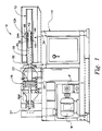
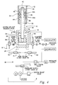
- the testing apparatus 10 includes a frame 14 upon which are mounted a test mandrel 16 and a hydraulic cylinder assembly 18 disposed in axial alignment with the test mandrel.
- the hydraulic cylinder assembly 18 is composed of a hollow cylinder housing 20 mounted on the frame 14 and a cylindrical piston 22 mounted in the cylinder housing 20 in spaced relation to and between opposite forward and rearward ends 24, 26 thereof.
- the piston 22 In a forward and aft direction along a common axis A of the mandrel 16 and assembly 18, the piston 22 is capable of undergoing reciprocal movement through pressure-generating and pressure-releasing strokes within the cylinder housing 20.
- a stop mechanism 27 at the rear of the hydraulic cylinder assembly 18 is adjustable for control of the piston stroke and element 34 expansion.
- the testing apparatus 10 includes power means, generally indicated by the numeral 28 in Fig. 4, connected in communication with the opposite forward and rearward ends 24, 26 of the cylinder housing 20 and being actuatable to feed hydraulic fluid under pressure to the housing ends to drive the piston 22 through its respective strokes.
- the power means 28 will be described in detail later on.
- test mandrel 16 of the testing apparatus 10 is coaxially aligned along common axis A with the hydraulic cylinder assembly 18. More particularly, the test mandrel 16 includes an elongated hollow open-ended sleeve 30, an elongated rigid member or drawbar 32, and a deformable member 34.
- the hollow sleeve 30 of the test mandrel 16 is stationarily mounted on the frame 10 in cantilevered fashion with a rearward or inner end 36 of the sleeve being rigidly connected to the cylinder housing 20 by fasteners 37.
- the sleeve 30 is adapted to receive thereover the hollow vessel 12 in such manner that a portion 12A (see also Fig. 4) of the vessel 12 to be tested extends beyond the sleeve outer end 38.
- the drawbar 32 of the test mandrel 16 is disposed coaxially within and extends through the open-ended sleeve 30.
- the drawbar 32 functions as an extension of a piston rod being rigidly attached at its rearward or inner end 40 to the forward side of the piston 22.
- the drawbar 32 extends beyond the outer end 38 of the hollow sleeve 30 and is coextensive with the vessel portion 12A to be tested. Due to its attachment to the piston 22, the drawbar 32 is movable therewith relative to the stationary sleeve 30 through the respective pressure-generating and pressure-releasing strokes.
- the sleeve 30 and drawbar 32 at their respective outer ends 38 and 42 have attached thereon annular header or end plates 44 and 46.
- the drawbar end plate 46 is spaced axially from the sleeve end plate 44.
- the resiliently yieldably annular deformable member 34 of the test mandrel 16 is mounted about the drawbar 32 and located between the sleeve and drawbar end plates 44, 46. At such location, the deformable member 34 is carried on the portion of the drawbar 32 which extends beyond the outer end 38 of the sleeve 30 and, thus, is disposed within the vessel portion 12A to be tested.
- a nut 48 is threaded on the drawbar outer end 42 to retain the drawbar end plate 46 thereon and the deformable member 34 at its axially displaced opposite ends disposed respectively in contact with the sleeve and drawbar end plates 44, 46.
- the outside diameter of the deformable member 34 is slightly less than the inside diameter of the vessel 12 to be tested.
- the deformable member 34 is formed of a plurality of doughnut-, puck- or ring-shaped elements 34A composed preferably of polyurethane elastomer material.
- the member When mechanical pressure is applied in compressive fashion to either one or both opposite ends of the deformable elastomer member 34 so as to draw or squeeze its elements 34A together, the member radially expands increasing its outside diameter. Once the compressive force is released, the material returns to its original outside diameter size.
- the deformable member 34 may be shaped externally to conform to and fill the shape of the cavity of the vessel being pressure tested so long as it is possible to insert the deformable member 34 into and afterwards withdraw it from the vessel.
- the urethane used for the annular deformable member 34 could vary in chemical formula depending on the maximum pressure range sought.
- this urethane product When surface lubricated properly, this urethane product applies consistent, uniform, hydrostatic replicating pressure within the chamber or vessel being tested; and, when the mechanical confining force is released, the urethane elastomer returns to its original or former (smaller or natural) state and size. This allows immediate reuse of the test mandrel 16 on another vessel or for another test of different factors.
- the deformable member 34 is adapted to expand radially so as to apply the desired mechanical pressure against the interior of the vessel portion 12A being tested upon movement of the piston 22 and the drawbar 32 therewith through the pressure-generating stroke relative to the stationary sleeve 30.
- Such movement of the drawbar 32 causes axial movement of its outer end plate 46 toward the sleeve outer end plate 44 and thereby application of compressive force against the opposite ends of the deformable member 34 to produce such outward radial expansion thereof.
- the deformable member 34 is adapted to contract radially so as to release application of the mechanical pressure against the interior of the vessel portion 12A upon movement of the piston 22 and the drawbar 32 therewith through the opposite, pressure-releasing stroke relative to the stationary sleeve 30.
- Such movement of the drawbar 32 causes axial movement of its outer end plate 46 away from the sleeve end plate 44 and thereby release of application of compressive force against the opposite ends of the deformable member to permit such inward radial contraction thereof.
- the testing apparatus 10 further includes means in the form of electronic pressure transducers 50 embedded in the drawbar 32 and deformable member 34 which directly sense the mechanical pressure exerted by the elastomer deformable member 34 against the interior of the vessel portion 12A being tested.
- the electrical signals from the transducers 50 are transmitted to components (not shown) such as multichanneled data acquisition oscilloscope, multiplexers and computers.
- components such as multichanneled data acquisition oscilloscope, multiplexers and computers.
- Various measurements can be made, such as pounds of pressure per square inch (psi) applied, specific rate and duration of pressure application, and shock pressure, pressure fall and rise response curves can be calculated.
- Figs. 3 and 4 illustrate some of the electrical and hydraulic components for actuating the piston 22 and the drawbar 32 therewith of the apparatus 10 through their pressure-generating and pressure-releasing strokes for carrying out the steps involved in the method of pressure burst testing of the vessel 12.
- the hydraulic circuit includes a motor M which operates a pump P to feed fluid under pressure from a reservoir R through a supply valve 52 to the forward end 24 of the cylinder housing 20 and the forward side of the piston 22 therein, or to both ends of the housing 20 and sides of the piston 22 if a cylinder return solenoid 54 has been actuated to open the cylinder return valve 56 connected thereto.
- the power means 28 is operable in two modes: one is a static mode and the other is a dynamic mode.
- a static test solenoid 58 is actuated to open the static test valve 60 connected thereto.
- dynamic test solenoids 62 are actuated simultaneously to open the high volume valves 64.
- a static mode a controlled gradual evacuation of fluid from the rearward end 26 of the cylinder housing 20 takes place, allowing a gradual increase in pressure to occur in the forward end 24 thereof.
- an instantaneous (such as lasting only 5 milliseconds) evacuation of fluid from the rearward end of the cylinder housing occurs, allow an instantaneous increase in pressure in the forward end thereof.
- the various solenoids and their valves are actuated by push buttons electrically connected to the solenoids and between electrical supply lines L of the electrical circuit 66, being illustrated in Fig. 5.
- a protective cover 68 (Figs. 1 and 2) must be closed to actuate a solenoid 70 (Fig. 4) which opens the supply valve 52.
- the return of the piston 22 to its initial position is caused by depression of a push button 72 which actuates the cylinder return solenoid 54.
- the static test is started by depression of a push button 74 which actuates the static test solenoid 58.
- the dynamic test is started by depression of push button 76 which actuates the dynamic test solenoids 62. It can be seen that the circuit connections and switches associated with the push buttons are such that only one of the solenoids 54, 58 and 62 can be actuated at a given time.
- the hollow sleeve 30, drawbar 32 and deformable member 34 are arranged as described above.
- the hollow vessel 12 is placed over the outer end 38 of the stationary sleeve 30 such that the vessel portion 12A to be tested extends beyond the sleeve outer end 38 and over the deformable member 34 mounted on the drawbar outer end 42.
- the protective cover 68 is then closed and the solenoid 70 is actuated to open the supply valve 52.
- either pushbutton 74 or 76 is depressed, causing the piston 22 and drawbar 32 therewith to move relative to the sleeve 30 through the pressure-applying stroke (toward the left in Fig. 1 and toward the bottom in Fig. 4) so as to move the drawbar end plate 46 toward the sleeve end plate 44 and apply a compressive force against opposite ends of the deformable member 34.
- Application of the compressive force causes the member 34 to expand radially and apply an expansive mechanical pressure against the interior of the vessel portion 12A to be tested.
- the push button 72 is depressed, causing the piston 22 and drawbar 32 therewith to then move in reverse fashion relative to the hollow sleeve 30 through a pressure-releasing stroke so as to move the drawbar end plate 46 away from the sleeve end plate 44 and release application of the compressive force against opposite ends of the deformable member 34. Release of the compressive force allows the deformable member 34 to contract radially to its original diameter size and release application of the mechanical pressure against the interior of the vessel portion 12A.
- the method of the present invention due to its controllability as regards pressure and time duration range, is believed to be the only method whereby particularly exotic "laminated construction" vessels may be produced, manufactured, tested and distributed under a qualification program involving acoustic or sonic inspection and evaluation wherein "actual use” pressure need not be actually applied. Instead, a nondestructive, lower, representative pressure can be used to establish the tested unit's "signature response" on predeveloped/worked-up time, pressure, and frequency curves giving behavioral characteristics at specifically applied pressures.
- Exotic laminate construction products do not lend themselves well to sustained hydraulic high-pressure testing as the elastic bonding agent will cold flow, releasing its bond to the fibers of the basic strength materials. This bond release causes a slow delamination and fluid or moisture penetration or leakage. This delamination is not always detectable sonically or if oil has penetrated the delamination the resultant contamination of the product is unacceptable.
- Explosive dynamically applied pressure is, of course, not compatible to sonic testing due to excessive "noise" generation and instantaneous catastrophic nature of the application.
- Chambers or vessels designed as once-only used products (such as specific weaponry) which require the use of costly exotic methods and materials in their construction, almost always require that sonic test response curves be used in their evaluations, and the expanding urethane mandrel method of pressure application disclosed herein is the most or only compatible method that tests yet saves the product, does not contaminate it, is safe to test personnel, does not require extraordinary facilities, and is extremely economical and reusable.
Landscapes
- Physics & Mathematics (AREA)
- Health & Medical Sciences (AREA)
- Life Sciences & Earth Sciences (AREA)
- Chemical & Material Sciences (AREA)
- Analytical Chemistry (AREA)
- Biochemistry (AREA)
- General Health & Medical Sciences (AREA)
- General Physics & Mathematics (AREA)
- Immunology (AREA)
- Pathology (AREA)
- Investigating Strength Of Materials By Application Of Mechanical Stress (AREA)
Applications Claiming Priority (2)
| Application Number | Priority Date | Filing Date | Title |
|---|---|---|---|
| US07/154,418 US4793179A (en) | 1988-02-10 | 1988-02-10 | Apparatus and method for pressure burst testing of a vessel |
| US154418 | 1988-02-10 |
Publications (2)
| Publication Number | Publication Date |
|---|---|
| EP0328005A2 true EP0328005A2 (de) | 1989-08-16 |
| EP0328005A3 EP0328005A3 (de) | 1991-04-03 |
Family
ID=22551289
Family Applications (1)
| Application Number | Title | Priority Date | Filing Date |
|---|---|---|---|
| EP19890101966 Withdrawn EP0328005A3 (de) | 1988-02-10 | 1989-02-04 | Verfahren und Vorrichtung zur Berstdruckprüfung eines Behälters |
Country Status (2)
| Country | Link |
|---|---|
| US (1) | US4793179A (de) |
| EP (1) | EP0328005A3 (de) |
Cited By (2)
| Publication number | Priority date | Publication date | Assignee | Title |
|---|---|---|---|---|
| DE4403770A1 (de) * | 1994-02-02 | 1995-08-31 | Mannesmann Ag | Verfahren zur Erfassung der elastisch-plastischen Dehnung bei der Druckprobe von Behältern |
| CN109507015A (zh) * | 2018-12-18 | 2019-03-22 | 上海航天化工应用研究所 | 一种五工位固体推进剂常高温应力松弛试验装置和方法 |
Families Citing this family (14)
| Publication number | Priority date | Publication date | Assignee | Title |
|---|---|---|---|---|
| US4930391A (en) * | 1989-07-24 | 1990-06-05 | Kapp Joseph A | Method and apparatus for fatigue and fracture testing of large caliber cannons |
| US6584850B2 (en) * | 2000-07-06 | 2003-07-01 | Colby Daniel H | Universal regulator tester |
| US6640614B1 (en) * | 2002-07-17 | 2003-11-04 | Molon, Inc. | Package burst pressure simulator |
| US7363821B2 (en) * | 2006-08-28 | 2008-04-29 | Cordis Corporation | Systems and methods for fatigue testing stents |
| US8256086B2 (en) * | 2009-06-25 | 2012-09-04 | Lockheed Martin Corporation | Method of producing missile nose cones |
| US9297219B2 (en) * | 2014-03-15 | 2016-03-29 | Dmar Engineering, Inc. | Umbilical buckling testing |
| CN106644231B (zh) * | 2016-12-08 | 2019-03-08 | 西安近代化学研究所 | 测量可移动靶标冲击波压力峰值的效应靶结构及测试方法 |
| CN110118914A (zh) * | 2019-04-30 | 2019-08-13 | 广州供电局有限公司 | 防爆盒检测装置及防爆盒检测方法 |
| CN110118699A (zh) * | 2019-04-30 | 2019-08-13 | 广州供电局有限公司 | 线缆防爆盒检测装置 |
| CN113325126B (zh) * | 2021-04-20 | 2022-05-27 | 北京理工大学 | 基于激光诱导爆燃对含能材料爆压的快速定量预测方法 |
| CN113295543B (zh) * | 2021-06-25 | 2023-04-11 | 临海伟星新型建材有限公司 | 一种管道高温爆破试验设备及方法 |
| CN115015085A (zh) * | 2022-06-22 | 2022-09-06 | 中国矿业大学 | 一种塑性混凝土防渗墙渗透破坏比降质量检测试验装置 |
| CN117233209B (zh) * | 2023-09-15 | 2024-07-16 | 广州海关技术中心 | 锂电池热失控气体爆炸极限装置、系统及使用方法 |
| CN119001055B (zh) * | 2024-08-13 | 2025-04-08 | 吉林通博化工有限公司 | 一种乳化生物质炸药检测用的装置及其方法 |
Family Cites Families (15)
| Publication number | Priority date | Publication date | Assignee | Title |
|---|---|---|---|---|
| US2362484A (en) * | 1943-05-10 | 1944-11-14 | Clarence N Hickman | Pressure gauge |
| US3043137A (en) * | 1958-09-29 | 1962-07-10 | Austin B J Clark | High pressure device |
| DE2128604A1 (de) * | 1971-06-09 | 1973-01-04 | Siemens Ag | Verfahren und vorrichtung zur pruefung von einseitig verschlossenen rohren, insbesondere von rohren in waermetauschern fuer atomkernreaktoren |
| US3693432A (en) * | 1971-06-22 | 1972-09-26 | Us Army | Artillery gun shock simulator |
| DE2139735C3 (de) * | 1971-08-07 | 1974-02-21 | Rheinmetall Gmbh, 4000 Duesseldorf | Einrichtung zum Simulieren der Schußbeanspruchung von Geschützrohren |
| US3960018A (en) * | 1973-07-23 | 1976-06-01 | Pcb Piezotronics, Inc. | Conformal pressure transducer |
| US3946607A (en) * | 1975-07-25 | 1976-03-30 | The United States Of America As Represented By The Secretary Of The Navy | Apparatus for measuring chamber pressure |
| US4088907A (en) * | 1976-10-29 | 1978-05-09 | Westinghouse Electric Corp. | Piezoelectric acoustic emission instrumentation |
| US4143617A (en) * | 1977-02-16 | 1979-03-13 | Raytheon Company | Rocket motor life indicator |
| US4194388A (en) * | 1978-12-18 | 1980-03-25 | Kaiser Aluminum & Chemical Corporation | Can testing device |
| US4263807A (en) * | 1979-09-04 | 1981-04-28 | The United States Of America As Represented By The Secretary Of The Army | Gun barrel stress simulator |
| US4317373A (en) * | 1980-03-03 | 1982-03-02 | Goes Michael J | Fatigue cycle sensor and method |
| US4356720A (en) * | 1981-02-04 | 1982-11-02 | The United States Of America As Represented By The Secretary Of The Army | Burst-pressure test fixture for pressure vessels dynamic rocket motors |
| US4419881A (en) * | 1982-05-04 | 1983-12-13 | The United States Of America As Represented By The Secretary Of The Army | Hydrodynamic pressurizing apparatus |
| GB8517485D0 (en) * | 1985-07-10 | 1985-08-14 | Brotherton & Thomas Glossop Lt | Pressure testing components |
-
1988
- 1988-02-10 US US07/154,418 patent/US4793179A/en not_active Expired - Fee Related
-
1989
- 1989-02-04 EP EP19890101966 patent/EP0328005A3/de not_active Withdrawn
Cited By (3)
| Publication number | Priority date | Publication date | Assignee | Title |
|---|---|---|---|---|
| DE4403770A1 (de) * | 1994-02-02 | 1995-08-31 | Mannesmann Ag | Verfahren zur Erfassung der elastisch-plastischen Dehnung bei der Druckprobe von Behältern |
| CN109507015A (zh) * | 2018-12-18 | 2019-03-22 | 上海航天化工应用研究所 | 一种五工位固体推进剂常高温应力松弛试验装置和方法 |
| CN109507015B (zh) * | 2018-12-18 | 2021-11-30 | 上海航天化工应用研究所 | 一种五工位固体推进剂常高温应力松弛试验装置和方法 |
Also Published As
| Publication number | Publication date |
|---|---|
| EP0328005A3 (de) | 1991-04-03 |
| US4793179A (en) | 1988-12-27 |
Similar Documents
| Publication | Publication Date | Title |
|---|---|---|
| US4793179A (en) | Apparatus and method for pressure burst testing of a vessel | |
| US4635333A (en) | Tube expanding method | |
| US4074527A (en) | Self-contained power subsystem | |
| US5425276A (en) | Material testing system providing simultaneous force loads | |
| US3910087A (en) | Hydraulic-forming machine | |
| EP0886770B1 (de) | Hopkinson-spaltstab testvorrichtung | |
| US20090211239A1 (en) | Pressure accumulator to establish sufficient power to handle and operate external equipment and use thereof | |
| KR100536959B1 (ko) | 진삼축압축시험장치 | |
| JPS6246722B2 (de) | ||
| US4419881A (en) | Hydrodynamic pressurizing apparatus | |
| US2537096A (en) | High acceleration shock testing air gun | |
| GB2086525A (en) | Improvements in internal obturators for pipes | |
| CN109534211B (zh) | 一种柔性千斤顶 | |
| US20080190286A1 (en) | Blast simulator with high velocity actuator | |
| US2754677A (en) | Nondestructive testing of thin shells by differential pressure | |
| US4250742A (en) | Method and apparatus for testing hardness of homogeneous materials | |
| CN119043958B (zh) | 一种长时序超高加速度电热co2加速装置及其控制方法 | |
| JP3310873B2 (ja) | 水中衝撃圧力発生装置 | |
| USH206H (en) | Dynamic pressure calibrator | |
| US4103849A (en) | Catapult restraint/release system | |
| Thiruvarudchelvan et al. | Computer-monitored hydraulic bulging of tubes | |
| US4263807A (en) | Gun barrel stress simulator | |
| US20070118325A1 (en) | Device and method for controlling the state of an energy accumulator | |
| US3540213A (en) | Hydraulic actuator and method | |
| US3208646A (en) | Hydropneumatic accumulator |
Legal Events
| Date | Code | Title | Description |
|---|---|---|---|
| PUAI | Public reference made under article 153(3) epc to a published international application that has entered the european phase |
Free format text: ORIGINAL CODE: 0009012 |
|
| AK | Designated contracting states |
Kind code of ref document: A2 Designated state(s): DE FR GB IT SE |
|
| PUAL | Search report despatched |
Free format text: ORIGINAL CODE: 0009013 |
|
| AK | Designated contracting states |
Kind code of ref document: A3 Designated state(s): DE FR GB IT SE |
|
| 17P | Request for examination filed |
Effective date: 19910930 |
|
| RAP1 | Party data changed (applicant data changed or rights of an application transferred) |
Owner name: ALLIANT TECHSYSTEMS INC. |
|
| STAA | Information on the status of an ep patent application or granted ep patent |
Free format text: STATUS: THE APPLICATION HAS BEEN WITHDRAWN |
|
| 18W | Application withdrawn |
Withdrawal date: 19920923 |