EP0327777A1 - Wegsensor für eine automatische Maschine - Google Patents
Wegsensor für eine automatische Maschine Download PDFInfo
- Publication number
- EP0327777A1 EP0327777A1 EP88420041A EP88420041A EP0327777A1 EP 0327777 A1 EP0327777 A1 EP 0327777A1 EP 88420041 A EP88420041 A EP 88420041A EP 88420041 A EP88420041 A EP 88420041A EP 0327777 A1 EP0327777 A1 EP 0327777A1
- Authority
- EP
- European Patent Office
- Prior art keywords
- disc
- shaft
- discs
- main shaft
- linked
- Prior art date
- Legal status (The legal status is an assumption and is not a legal conclusion. Google has not performed a legal analysis and makes no representation as to the accuracy of the status listed.)
- Withdrawn
Links
Images
Classifications
-
- G—PHYSICS
- G01—MEASURING; TESTING
- G01D—MEASURING NOT SPECIALLY ADAPTED FOR A SPECIFIC VARIABLE; ARRANGEMENTS FOR MEASURING TWO OR MORE VARIABLES NOT COVERED IN A SINGLE OTHER SUBCLASS; TARIFF METERING APPARATUS; MEASURING OR TESTING NOT OTHERWISE PROVIDED FOR
- G01D5/00—Mechanical means for transferring the output of a sensing member; Means for converting the output of a sensing member to another variable where the form or nature of the sensing member does not constrain the means for converting; Transducers not specially adapted for a specific variable
- G01D5/12—Mechanical means for transferring the output of a sensing member; Means for converting the output of a sensing member to another variable where the form or nature of the sensing member does not constrain the means for converting; Transducers not specially adapted for a specific variable using electric or magnetic means
- G01D5/244—Mechanical means for transferring the output of a sensing member; Means for converting the output of a sensing member to another variable where the form or nature of the sensing member does not constrain the means for converting; Transducers not specially adapted for a specific variable using electric or magnetic means influencing characteristics of pulses or pulse trains; generating pulses or pulse trains
- G01D5/245—Mechanical means for transferring the output of a sensing member; Means for converting the output of a sensing member to another variable where the form or nature of the sensing member does not constrain the means for converting; Transducers not specially adapted for a specific variable using electric or magnetic means influencing characteristics of pulses or pulse trains; generating pulses or pulse trains using a variable number of pulses in a train
- G01D5/2454—Encoders incorporating incremental and absolute signals
- G01D5/2455—Encoders incorporating incremental and absolute signals with incremental and absolute tracks on the same encoder
- G01D5/2457—Incremental encoders having reference marks
Definitions
- the present invention relates to displacement encoders which, in robots, automata, machining centers and other automatic machines, are associated with the various mobile members with a view to locating the exact position of each of them in the movement sequence.
- displacement encoders comprising a first disc angularly linked to the displacement of the member considered, a second disc angularly linked to the first in a ratio close to 1 but different from this value, and means for counting pulses associated with each of the discs in order to detect the angular offset existing between them.
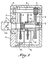
- the present invention mainly intends to remedy, which relates to a displacement encoder of the "differential" type, characterized in that the first disc is wedged on a main shaft secured to the movable member considered while the second is mounted idly on said shaft, so that the two discs are arranged coaxially on the latter while being linked together by means of two toothed wheels which are themselves arranged coaxially on the main shaft and which cooperate with a common pinion carried by a secondary shaft oriented parallel to said main shaft.
- reference 1 designates a housing inside which axially rotates a main shaft 2, supported in two opposite bearings 3.
- One end of the shaft 2 extends outside the housing 1 and is designed as a 2 so as to allow its coupling to the shaft 4 ensures that the control of the angular or linear of the movable member of the machine whose position you want to be able to locate at any time.
- a disc 5 On the main shaft 2 are wedged on the one hand a disc 5, on the other hand a toothed wheel 6, which meshes with a pinion 7 secured to a secondary shaft 8 mounted idly inside of bearings 9 provided in the housing 1.
- the pinion 7 meshes simultaneously with a second toothed wheel 10 secured to a hub 11 which rotates freely on the shaft 2 behind the disc 5.
- the wheels 6 and 10 have very slightly different numbers of teeth (a difference of one tooth is enough) so that, as a result of this differential connection, the two discs 5 and 12 are made angularly integral according to a ratio close to 1, but different from this value.
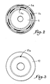
- the disc 5 has three scales or concentric tracks respectively referenced 5 a , 5 b and 5 c .
- the two tracks 5 a and 5 b have the same number of marks, but these are angularly offset from one track to another; track 5 c can include a variable number of marks, only one in the embodiment considered.
- the disc 12 has only one track 12 a having a number of marks equal to that of track 5 c of the disc 5, that is to say one in the case envisaged.
- Each of these discs 5 and 12 is associated with a detector 13, respectively 14, comprising a number of detection members obviously equal to that of the tracks presented by the disc which corresponds to it.
- the nature of these detection members depends on that of the markers which constitute the tracks of the discs 5 and 12; they may be photoelectric cells, magnetic sensors or any other device capable of generating an incremental pulse when each mark of the corresponding track passes during the rotation of the disks 5 and 12, which pulse is transmitted to a counting device enclosed in the control cabinet of the envisaged machine.
- the operation of the encoder described above is analogous to that of conventional devices of the same type. It will be assumed that the encoder is fixed to the rear of the motor which ensures the linear movement of the arm of a robot or automaton.
- the discs 5 and 12 have been adjusted beforehand so that at half the stroke of the envisaged arm, the marks of the tracks 5 c and 12 a are simultaneously in coincidence with the corresponding detection member of one and the other of the two detectors 13 and 14.
- the arm considered will of course move on either side of this middle position while ensuring the rotational drive of the two discs 5 and 12.
- the marks of the tracks 5 c and 12 a will shift relative to each other, so that at any time, to determine the position of the robot's bra, it just move this arm over a maximum distance corresponding to one revolution and read the angular offset between the two tracks or marks 5 c and 12 a , this reading being carried out by counting pulses at the level of tracks 5 a and 5 b disc 5.
- Counting pulses generated by detectors 13 and 14 for the passage of pins from the slopes 5c and 12 has discs 5 and 12 involves no analog processing, such that it is simple and reliable.
- the device only has a very small footprint and is therefore likely to be very easily installed on the machine at each of the movable members thereof.
Priority Applications (2)
| Application Number | Priority Date | Filing Date | Title |
|---|---|---|---|
| FR8618310A FR2608756B1 (fr) | 1986-12-19 | 1986-12-19 | Capteur de deplacement pour machines automatiques |
| EP88420041A EP0327777A1 (de) | 1988-02-12 | 1988-02-12 | Wegsensor für eine automatische Maschine |
Applications Claiming Priority (1)
| Application Number | Priority Date | Filing Date | Title |
|---|---|---|---|
| EP88420041A EP0327777A1 (de) | 1988-02-12 | 1988-02-12 | Wegsensor für eine automatische Maschine |
Publications (1)
| Publication Number | Publication Date |
|---|---|
| EP0327777A1 true EP0327777A1 (de) | 1989-08-16 |
Family
ID=8200460
Family Applications (1)
| Application Number | Title | Priority Date | Filing Date |
|---|---|---|---|
| EP88420041A Withdrawn EP0327777A1 (de) | 1986-12-19 | 1988-02-12 | Wegsensor für eine automatische Maschine |
Country Status (1)
| Country | Link |
|---|---|
| EP (1) | EP0327777A1 (de) |
Cited By (7)
| Publication number | Priority date | Publication date | Assignee | Title |
|---|---|---|---|---|
| EP1084726A2 (de) | 1995-04-14 | 2001-03-21 | Glaxo Wellcome Inc. | Dosierinhalator für Fluticasonpropionat |
| WO2001098176A2 (en) | 2000-06-22 | 2001-12-27 | Glaxo Group Limited | Package for a pressurized container containing a drug |
| WO2001098175A1 (en) | 2000-06-20 | 2001-12-27 | Glaxo Group Limited | Method and package for storing a pressurized container containing a drug |
| EP1366777A1 (de) | 1995-04-14 | 2003-12-03 | SmithKline Beecham Corporation | Dosierinhalator für Salmeterol |
| EP1870122A2 (de) | 1995-04-14 | 2007-12-26 | SmithKline Beecham Corporation | Inhalator für abgemessene Dosen |
| EP2275479A1 (de) | 2003-08-11 | 2011-01-19 | Glaxo Group Limited | Pharmazeutuscher Dosierinhalator und zugehörige Verfahren |
| CN109556641A (zh) * | 2018-11-30 | 2019-04-02 | 重庆智慧水务有限公司 | 一种光电传感器的格雷码均匀度检测方法 |
Citations (3)
| Publication number | Priority date | Publication date | Assignee | Title |
|---|---|---|---|---|
| GB1565400A (en) * | 1975-12-18 | 1980-04-23 | Otis Elevator Co | High resolution and wide range shaft position transducer systems |
| US4284028A (en) * | 1979-02-14 | 1981-08-18 | Swanburg Mark G | English/metric conversion mechanism for speedometers |
| US4358753A (en) * | 1981-03-16 | 1982-11-09 | Rockwell International Corporation | High resolution shaft position encoder |
-
1988
- 1988-02-12 EP EP88420041A patent/EP0327777A1/de not_active Withdrawn
Patent Citations (3)
| Publication number | Priority date | Publication date | Assignee | Title |
|---|---|---|---|---|
| GB1565400A (en) * | 1975-12-18 | 1980-04-23 | Otis Elevator Co | High resolution and wide range shaft position transducer systems |
| US4284028A (en) * | 1979-02-14 | 1981-08-18 | Swanburg Mark G | English/metric conversion mechanism for speedometers |
| US4358753A (en) * | 1981-03-16 | 1982-11-09 | Rockwell International Corporation | High resolution shaft position encoder |
Cited By (10)
| Publication number | Priority date | Publication date | Assignee | Title |
|---|---|---|---|---|
| EP1084726A2 (de) | 1995-04-14 | 2001-03-21 | Glaxo Wellcome Inc. | Dosierinhalator für Fluticasonpropionat |
| EP1166811A2 (de) | 1995-04-14 | 2002-01-02 | SmithKline Beecham Corporation | Dosierinhalator für Fluticasonepropionat |
| EP1366777A1 (de) | 1995-04-14 | 2003-12-03 | SmithKline Beecham Corporation | Dosierinhalator für Salmeterol |
| EP1870122A2 (de) | 1995-04-14 | 2007-12-26 | SmithKline Beecham Corporation | Inhalator für abgemessene Dosen |
| EP1908488A2 (de) | 1995-04-14 | 2008-04-09 | SmithKline Beecham Corporation | Dosierinhalator für Salmeterol |
| WO2001098175A1 (en) | 2000-06-20 | 2001-12-27 | Glaxo Group Limited | Method and package for storing a pressurized container containing a drug |
| WO2001098176A2 (en) | 2000-06-22 | 2001-12-27 | Glaxo Group Limited | Package for a pressurized container containing a drug |
| EP2275479A1 (de) | 2003-08-11 | 2011-01-19 | Glaxo Group Limited | Pharmazeutuscher Dosierinhalator und zugehörige Verfahren |
| CN109556641A (zh) * | 2018-11-30 | 2019-04-02 | 重庆智慧水务有限公司 | 一种光电传感器的格雷码均匀度检测方法 |
| CN109556641B (zh) * | 2018-11-30 | 2020-10-02 | 重庆智慧水务有限公司 | 一种光电传感器的格雷码均匀度检测方法 |
Similar Documents
| Publication | Publication Date | Title |
|---|---|---|
| EP0765463B1 (de) | Verfahren zum lokaliseren eines trieders im raum | |
| FR2505717A1 (fr) | Systeme de mesure de dimensions desservi par une multiplicite de bras manipulateurs et commande par un systeme calculateur | |
| FR2505716A1 (fr) | Ensemble de bras manipulateur commande par un systeme calculateur | |
| US3693024A (en) | Rotational shaft encoder having a bearing tube having a slot therein | |
| EP1666833B1 (de) | Motorisierter und orientierbarer Messkopf | |
| EP0327777A1 (de) | Wegsensor für eine automatische Maschine | |
| EP1403622A1 (de) | Absoluter Drehgeber | |
| CH617506A5 (de) | ||
| US4841297A (en) | Displacement coder | |
| JP3527468B2 (ja) | 回転および回動角度測定用減速ギア | |
| FR2608756A1 (fr) | Capteur de deplacement pour machines automatiques | |
| FR2750492A1 (fr) | Procede et dispositif pour positionner des pieces mobiles de machines | |
| US4541291A (en) | Automatic sampling arrangement | |
| EP2335027A1 (de) | Optischer codierer | |
| EP1403621B1 (de) | Absoluter Drehgeber | |
| EP0203010A1 (de) | Vorrichtung zur berührungslosen Messung von Abmessungen eines Parallelepipedons | |
| FR2492092A1 (fr) | Dispositif de reperage de la position de reference d'une piece mobile en translation | |
| FR2490335A1 (fr) | Horizon artificiel pour aeronef | |
| FR2632232A1 (fr) | Dispositif de positionnement de la table d'une machine-outil d'usinage des metaux par coupe | |
| JP3031539B2 (ja) | 自動工具交換装置の駆動装置 | |
| EP1874507B1 (de) | Antriebsvorrichtung für ein kombinierte drehbewegungen ausführendes objekt | |
| JPS57191827A (en) | Moving magnetic head with reference position detecting mechanism | |
| JPS6113982Y2 (de) | ||
| BE1014105A5 (fr) | Dispositif de mesure de la position angulaire relatif d'un organe rotatif par rapport a une structure fixe. | |
| FR2678728A1 (fr) | Systeme gyroscopique a mesure de l'inclinaison du plan des axes des cadres primaire et secondaire par rapport aux axes de rotation desdits cadres. |
Legal Events
| Date | Code | Title | Description |
|---|---|---|---|
| PUAI | Public reference made under article 153(3) epc to a published international application that has entered the european phase |
Free format text: ORIGINAL CODE: 0009012 |
|
| AK | Designated contracting states |
Kind code of ref document: A1 Designated state(s): BE CH DE ES GB IT LI SE |
|
| 17P | Request for examination filed |
Effective date: 19891003 |
|
| 17Q | First examination report despatched |
Effective date: 19910529 |
|
| STAA | Information on the status of an ep patent application or granted ep patent |
Free format text: STATUS: THE APPLICATION IS DEEMED TO BE WITHDRAWN |
|
| 18D | Application deemed to be withdrawn |
Effective date: 19911009 |