EP0327374B1 - Bus air conditioning unit - Google Patents
Bus air conditioning unit Download PDFInfo
- Publication number
- EP0327374B1 EP0327374B1 EP89301038A EP89301038A EP0327374B1 EP 0327374 B1 EP0327374 B1 EP 0327374B1 EP 89301038 A EP89301038 A EP 89301038A EP 89301038 A EP89301038 A EP 89301038A EP 0327374 B1 EP0327374 B1 EP 0327374B1
- Authority
- EP
- European Patent Office
- Prior art keywords
- bus
- evaporator
- air
- blowers
- passenger compartment
- Prior art date
- Legal status (The legal status is an assumption and is not a legal conclusion. Google has not performed a legal analysis and makes no representation as to the accuracy of the status listed.)
- Expired
Links
Images

Classifications
-
- B—PERFORMING OPERATIONS; TRANSPORTING
- B60—VEHICLES IN GENERAL
- B60H—ARRANGEMENTS OF HEATING, COOLING, VENTILATING OR OTHER AIR-TREATING DEVICES SPECIALLY ADAPTED FOR PASSENGER OR GOODS SPACES OF VEHICLES
- B60H1/00—Heating, cooling or ventilating devices
- B60H1/00357—Air-conditioning arrangements specially adapted for particular vehicles
- B60H1/00371—Air-conditioning arrangements specially adapted for particular vehicles for vehicles carrying large numbers of passengers, e.g. buses
-
- B—PERFORMING OPERATIONS; TRANSPORTING
- B60—VEHICLES IN GENERAL
- B60H—ARRANGEMENTS OF HEATING, COOLING, VENTILATING OR OTHER AIR-TREATING DEVICES SPECIALLY ADAPTED FOR PASSENGER OR GOODS SPACES OF VEHICLES
- B60H1/00—Heating, cooling or ventilating devices
- B60H1/00007—Combined heating, ventilating, or cooling devices
- B60H1/00207—Combined heating, ventilating, or cooling devices characterised by the position of the HVAC devices with respect to the passenger compartment
- B60H2001/00235—Devices in the roof area of the passenger compartment
-
- Y—GENERAL TAGGING OF NEW TECHNOLOGICAL DEVELOPMENTS; GENERAL TAGGING OF CROSS-SECTIONAL TECHNOLOGIES SPANNING OVER SEVERAL SECTIONS OF THE IPC; TECHNICAL SUBJECTS COVERED BY FORMER USPC CROSS-REFERENCE ART COLLECTIONS [XRACs] AND DIGESTS
- Y10—TECHNICAL SUBJECTS COVERED BY FORMER USPC
- Y10S—TECHNICAL SUBJECTS COVERED BY FORMER USPC CROSS-REFERENCE ART COLLECTIONS [XRACs] AND DIGESTS
- Y10S62/00—Refrigeration
- Y10S62/16—Roof and ceiling located coolers
Definitions
- the invention relates in general to air conditioning methods and apparatus, and more specifically to air conditioning units suitable for mounting on the top of a bus.
- Air conditioning units for buses often require that the evaporator and condenser sections thereof mount in the rear roof area of a bus without detracting from passenger head room in the passenger compartment, without significantly increasing the height of the bus, and without unduly complicating normal service procedures. These requirements are coupled with an additional restraint when the bus has a rear window, as the bus air conditioning unit must not interfere with rear window area.
- the air in the passenger compartment is directed through a closed air flow path which includes the bus air conditioning unit, and it is then returned to the passenger compartment after conditioning.
- This flow path includes an evaporator and air moving means such as a blower. Noise generated in the closed air flow path by the air moving means should be prevented from entering the passenger compartment.
- the present invention relates to a method, and air conditioning apparatus for performing the method, of directing air from the passenger compartment through a roof mounted evaporator of an air conditioning unit, and returning conditioned air to the passenger compartment via first and second air delivery ducts in the bus.
- the invention consists in a method of directing air from the passenger compartment in a bus having a front, a rear having a back plane, a longitudinal axis which extends between said front and rear, a roof, and a passenger compartment having a ceiling, through a roof mounted evaporator of an air conditioning unit, and returning conditioned air to the passenger compartment via first and second air delivery ducts, such a method is known from US-A-2784568, characterized by the steps of: dividing the evaporator into first and second transversely spaced evaporator sections, relative to the longitudinal axis of the bus; providing an air inlet grille below and between said first and second spaced evaporator sections, substantially in the plane of the ceiling of the passenger compartment; providing first and second blowers between said first and second evaporator sections, respectively, and the rear of the bus; drawing the air from the bus: (1) vertically upward through said air inlet grille, (2) transversely, relative to the longitudinal axis of the bus, through said first and second e
- the invention also consists in a air conditioning unit for a bus wherein the bus has a front, sides, rear and roof portions, a longitudinal axis which extends between the front and rear portions, a passenger compartment having a ceiling, first and second air delivery ducts in the passenger compartment, an evaporator disposed above the passenger ceiling, with the evaporator having first and second evaporator sections spaced transversely relative to the longitudinal axis of the bus, a return air grille disposed below and between the first and second spaced evaporator sections, substantially in the plane of the ceiling of the passenger compartment, first and second air outlet ducts, first and second evaporator blowers each having an inlet, and outlet and a rotational axis, with their rotational axes being substantially parallel with the longitudinal axis of the bus, and with their outlets connected to the first and second air outlet ducts, respectively, first and second evaporator plenums between the first and second evaporator sections and the inlets of the first and second evaporator
- the invention provides a desirable layout for the condenser and the associated condenser fans which enables two electric motors to be used to drive the two blowers and the two fans.
- the condenser is disposed behind the evaporator, between the evaporator and the rear of the bus, and also between the first and second blowers.
- the condenser has an air inlet plane which is adjacent to the plane of the bus roof, enabling it to be cleaned by rain and bus washing equipment.
- First and second condenser fan blades are disposed in spaced relation behind the first and second blowers, respectively, with the fan blades being in, or closely adjacent to, the back plane of the bus.
- the spaced first blower and first fan have their rotational axes aligned with one another, parallel with the longitudinal axis of the bus, and a first electric motor having a double shaft extension is disposed in the space and directly connected to the first blower and first fan.
- a second electric motor is similarly directly connected to the second blower and second fan.
- the first and second motors are preferably continuously operated during ventilating, heating and cooling modes of the air conditioning unit, for long motor life.
- All refrigeration components required to complete a refrigeration circuit with the evaporator and condenser, and all electrical controls for operating the air conditioning unit, are disposed for easy access from the rear of the bus, or from the passenger compartment by removing the return air grille, making it unnecessary for service personnel to gain access to the top of the bus for routine servicing.
- Removable covers protect the blowers, fans and motors from the elements, while providing quick access for servicing.
- Bus 10 having a roof top air conditioning unit 12 constructed according to the teachings of the invention.
- Bus 10 includes a front (not shown), a rear 14, first and second sides 16 and 18, a roof 20, and a longitudinal axis 22 which extends between the front and rear of the bus 10.
- Bus 10 additionally has a rear window 24, as well as windows on the sides, such as window 26 on side 16.
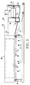
- the side elevational view of air conditioning unit 12 shown in Figure 3 illustrates a passenger compartment 28 and a ceiling liner 30.
- Ceiling liner 30 includes a horizontal portion 32 which extends towards the rear 14 of the bus and then terminates in a downwardly sloping portion 34 which continues the ceiling liner 30 to the back of the bus, terminating above the rear window 24.
- air conditioning unit 12 includes an evaporator 36 which is disposed above the horizontal portion 32 of the ceiling liner 30.
- Evaporator 36 is divided into first and second evaporator sections 38 and 40, respectively, and the first and second evaporator sections 38 and 40 are transversely spaced apart relative to the longitudinal axis 22.
- Each evaporator section has air inlet and outlet planes which extend in a direction parallel with the longitudinal axis 22 of the bus, such as air inlet and outlet planes 42 and 44, respectively, on evaporator section 38, and air inlet and outlet planes 46 and 48, respectively, on evaporator section 40.
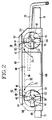
- FIG 2 which is a rear elevational view of air conditioning unit 12, instead of the air inlet and outlet planes being vertically oriented, they are skewed from the vertical by a predetermined angle, such as 30 degrees, for example, such that extensions of the inlet and outlet planes of one evaporator section intersect the inlet and outlet planes of the other evaporator section above roof 20.
- This arrangement increases the surface areas of the air inlet and outlet planes for a given vertical dimension of the evaporator sections, and the inverted vee configuration formed by the skewed evaporator sections facilitates redirecting rising return air from the passenger compartment through the evaporator sections 38 and 40.
- the ceiling liner portion 32 which is below and between the spaced evaporator sections 38 and 40 is removed and covered by a return air grille 50, as shown in Figure 3, and a filter (not shown) may be disposed above grille 50.
- Grille 50 is substantially in the same plane as ceiling liner portion 32, and thus does not project into the passenger compartment 28.
- First and second centrifugal blowers 52 and 54 are mounted behind and slightly outboard from evaporator sections 38 and 40, respectively, in the expanding space created by the downwardly sloping portion 34 of the ceiling liner 30.
- the rotational axes 56 and 58 of blowers 52 and 54, respectively, are oriented parallel with the longitudinal axis 22 of bus 10, and they are generally aligned with the air outlet planes 44 and 48 of evaporator sections 38 and 40, respectively.
- a housing 60 is disposed about evaporator sections 38 and 40.
- Housing 60 has a central portion 61 which insures that return air from the bus passenger compartment 28 is drawn into the air inlet planes 42 and 46 of evaporator sections 38 and 40.
- Housing 60 also has outboard portions 63 and 65 which form plenums 62 and 64, respectively, which insure that air which has passed through evaporator sections 38 and 40 is drawn from the air outlet planes 44 and 48 to the axially located inlets of blowers 52 and 54.
- Peripherally located outlets 66 and 68 of blowers 52 and 54 are connected to air outlet ducts 70 and 72, respectively, which direct air outwardly towards the sides 16 and 18 of bus 10 and then through smoothly curved right angle bends to bus air delivery ducts 67 and 69 located in passenger compartment 28.
- the hereinbefore described air flow arrangement does not diminish passenger head room in passenger compartment 28, and it provides an air flow path for conditioning the air in passenger compartment 28 which reduces air borne noise to an insignificant level.
- the noise reducing arrangement is provided by a new air flow method which includes directing the air through a plurality of right angle turns which absorb the noise, and prevent it from being transmitted to the passenger compartment 28 in either direction from blowers 52 and 54. In other words, noise cannot enter passenger compartment 28 via the openings defined by the return air grille 50, or via the passenger compartment air ducts 67 and 69.
- blowers 52 and 54 draw air from passenger compartment 28 vertically upward through the return air grille 50, as indicated by arrows 73 in Figure 3.
- Housing portion 61 of housing 60 directs the return air into first right angle turns transverse to the longitudinal axis 22 of bus 10, i.e., towards sides 16 and 18, into the skewed air inlet planes 42 and 46 of evaporator sections 38 and 40, as indicated by arrows 75 in Figure 2.
- the return air is conditioned in evaporator sections 38 and 40, and it exits therefrom via the air outlet planes 44 and 48 into plenums 62 and 64.
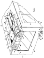
- Housing portions 63 and 65 of housing 60 direct the conditioned air through second right angle turns into longitudinal flow paths towards the rear 14 of bus 10, i.e., paths which are parallel with bus axis 22, as indicated by arrows 77 in Figure 1.
- the conditioned air is drawn into the axial inlets of blowers 52 and 54 and the blowers redirect the air through third right angle turns towards the sides 16 and 18 of bus 10, as indicated by arrows 79 in Figure 4.
- the peripherally located outlets 66 and 68 of blowers 52 and 54 are connected to air outlet ducts 70 and 72 which direct the air through fourth right angle turns into the longitudinally extending air delivery ducts 67 and 69 of the bus 10, as indicated by arrow 81 in Figure 4. Air leaving the air delivery ducts to enter the passenger compartment 28 again must proceed through right angle turns, further isolating the noise producing blowers 52 and 54 from the passenger compartment 28.
- the refrigerant circuit includes a compressor 74, shown in Figure 1, having a hot gas line 76 and a suction line 78.
- Compressor 74 may be driven by the bus engine, shown generally at 80, which is mounted at the lower rear of bus 10.
- each evaporator section 38 and 40 may have a cooling portion and a heating portion, such as cooling and heating portions 82 and 84 in evaporator section 38, and cooling and heating portions 86 and 88 in evaporator section 40.
- the cooling portions 82 and 86 are connected in the refrigeration circuit, which includes compressor 74, and the heating portions 84 and 88 may be connected to receive hot liquid coolant from a radiator 90 associated with the bus engine 80, as indicated by hot liquid coolant lines 91 and 93.
- Blowers 52 and 54 are driven by power sources, such as electric motors 95 and 97.
- motors 95 and 97 may be operated continuously while bus 10 is in service, to provide cooling, heating, or ventilation, extending the life of the motors.
- the refrigerant circuit additionally includes a condenser 92.
- Condenser 92 is located behind evaporator 36, i.e., between evaporator 36 and the rear 14 of bus 10, between blowers 52 and 54, and essentially above the sloping portion 34 of the ceiling liner 30.
- Condenser 92 has air inlet and outlet planes 94 and 96, respectively.
- Air inlet plane 94 is horizontally oriented and is located in substantially the same plane as the housing 60 which covers the evaporator sections 38 and 40, i.e., as high as the maximum height profile allows.
- This location provides unimpeded fresh air flow into condenser 92, it assures self cleaning due to rain, as well as cleaning by bus wash solutions, and it provides sufficient clearance below the air outlet plane 96 to provide a plenum 98 for containing heated ambient air and directing it to an exit along the back plane of the bus 10.
- Air is drawn into the air inlet plane 94 of condenser 92 via first and second fan blades 100 and 102, respectively, with fan blades 100 and 102 being driven by suitable power sources.
- the rotational axes of the fan blades are aligned with the rotational axes 56 and 58 of blowers 52 and 54, and motors 95 and 97 are provided with double shaft extensions, one for a blower and one for a fan blade.
- motor 95 drives evaporator blower 52 and condenser fan blade 100
- motor 97 drives evaporator blower 54 and fan blade 102.
- Fan blades 100 and 102 being located in the back plane of rear portion 14 of bus 10, project fan noise outwardly from the rear of the bus, isolating passenger compartment 28 from any noise produced by the condenser fans.
- Removable housings or covers 104 and 106 provide the functions of protecting motors 92 and 94, respectively, from rain and bus wash solutions, as well as providing quick access to the motors and other refrigeration circuit components, such as fittings, valves, drier, and receiver, for maintenance purposes. Covers 104 and 106 are easily reached from the rear of the bus via a service dolly.
- Electrical controls for controlling the air conditioning unit 12, as well as refrigeration circuit components, are disposed in a cabinet 108 disposed between condenser fans 100 and 102, thus preserving the concept that all electrical control and all refrigeration components, except the evaporator and condenser coils, are accessible and serviceable from the rear 14 of the bus 10, or by removing the return air grille 50 in the passenger compartment 28.
- the compressor 74 is in the engine compartment at the rear 14 of bus 10, and is also easily serviced.
Landscapes
- Physics & Mathematics (AREA)
- Thermal Sciences (AREA)
- Engineering & Computer Science (AREA)
- Mechanical Engineering (AREA)
- Air-Conditioning For Vehicles (AREA)
Description
- The invention relates in general to air conditioning methods and apparatus, and more specifically to air conditioning units suitable for mounting on the top of a bus.
- Air conditioning units for buses often require that the evaporator and condenser sections thereof mount in the rear roof area of a bus without detracting from passenger head room in the passenger compartment, without significantly increasing the height of the bus, and without unduly complicating normal service procedures. These requirements are coupled with an additional restraint when the bus has a rear window, as the bus air conditioning unit must not interfere with rear window area. Also, the air in the passenger compartment is directed through a closed air flow path which includes the bus air conditioning unit, and it is then returned to the passenger compartment after conditioning. This flow path includes an evaporator and air moving means such as a blower. Noise generated in the closed air flow path by the air moving means should be prevented from entering the passenger compartment.
- Thus, it would be desirable, and it is the object of the invention, to provide a new bus air conditioning unit, and to provide new methods of directing air through the bus air conditioning unit, which meet all the above stated requirements.
- The present invention relates to a method, and air conditioning apparatus for performing the method, of directing air from the passenger compartment through a roof mounted evaporator of an air conditioning unit, and returning conditioned air to the passenger compartment via first and second air delivery ducts in the bus. The invention consists in a method of directing air from the passenger compartment in a bus having a front, a rear having a back plane, a longitudinal axis which extends between said front and rear, a roof, and a passenger compartment having a ceiling, through a roof mounted evaporator of an air conditioning unit, and returning conditioned air to the passenger compartment via first and second air delivery ducts, such a method is known from US-A-2784568, characterized by the steps of: dividing the evaporator into first and second transversely spaced evaporator sections, relative to the longitudinal axis of the bus; providing an air inlet grille below and between said first and second spaced evaporator sections, substantially in the plane of the ceiling of the passenger compartment; providing first and second blowers between said first and second evaporator sections, respectively, and the rear of the bus; drawing the air from the bus: (1) vertically upward through said air inlet grille, (2) transversely, relative to the longitudinal axis of the bus, through said first and second evaporator sections, and (3) parallel with the longitudinal axis of the bus into said first and second blowers; discharging air from said first and second blowers transversely, relative to the longitudinal axis of the bus, into the first and second air delivery ducts; disposing a refrigerant condenser between the evaporator and the rear of the bus, and between the first and second blowers, with said condenser having a horizontally oriented air inlet plane adjacent to the plane of the roof; disposing first and second condenser fans substantially in the back plane of the bus; driving the first blower and first fan via a first common power source; driving the second blower and second fan via a second common power source; drawing air through said refrigerant condenser; and discharging the air drawn through the refrigerant condenser from the back plane of the bus via said first and second fans.
- The invention also consists in a air conditioning unit for a bus wherein the bus has a front, sides, rear and roof portions, a longitudinal axis which extends between the front and rear portions, a passenger compartment having a ceiling, first and second air delivery ducts in the passenger compartment, an evaporator disposed above the passenger ceiling, with the evaporator having first and second evaporator sections spaced transversely relative to the longitudinal axis of the bus, a return air grille disposed below and between the first and second spaced evaporator sections, substantially in the plane of the ceiling of the passenger compartment, first and second air outlet ducts, first and second evaporator blowers each having an inlet, and outlet and a rotational axis, with their rotational axes being substantially parallel with the longitudinal axis of the bus, and with their outlets connected to the first and second air outlet ducts, respectively, first and second evaporator plenums between the first and second evaporator sections and the inlets of the first and second evaporator blowers, respectively, with the first and second evaporator blowers drawing air from the passenger compartment of the bus vertically upward through the return air grille, transversely through the first and second evaporator sections, through the first and second evaporator plenums, and transversely through the first and second evaporator blowers into the first and second air outlet ducts, with the transverse direction being relative to the longitudinal axis of the bus, a refrigerant condenser disposed between the evaporator and the rear of the bus, with the condenser having a horizontally oriented air inlet plane adjacent to the plane of the bus roof, and first and second condenser fans longitudinally spaced from the first and second blowers respectively, characterized by, such a unit is known from US-A-2784568, said refrigerant condenser being disposed between the first and second blowers, and said first and second condenser fans being longitudinally aligned with the first and second blowers, to define first and second spaces between the blowers and fans, first and second electric motors disposed in said first and second spaces, with said first electric motor being directly connected to the first blower and to the first fan, and with said second electric motor being directly connected to the second blower and to the second fan, said first and second blowers forming first walls of the first and second plenums, respectively, which walls include inlets to the first and second blowers, and said first and second evaporator sections forming second wall of the first and second plenums, respectively, which walls include outlets of the first and second evaporator sections, said first and second walls of each of the first and second plenums being arranged at right angles relative to one another to provide a single 90 degree deviation of air exiting the outlets of the first and second evaporator sections and entering the inlets of the first and second blowers.
- In addition to the desirable air flow paths for the return air and the conditioned air, the invention provides a desirable layout for the condenser and the associated condenser fans which enables two electric motors to be used to drive the two blowers and the two fans. The condenser is disposed behind the evaporator, between the evaporator and the rear of the bus, and also between the first and second blowers. The condenser has an air inlet plane which is adjacent to the plane of the bus roof, enabling it to be cleaned by rain and bus washing equipment. First and second condenser fan blades are disposed in spaced relation behind the first and second blowers, respectively, with the fan blades being in, or closely adjacent to, the back plane of the bus. The spaced first blower and first fan have their rotational axes aligned with one another, parallel with the longitudinal axis of the bus, and a first electric motor having a double shaft extension is disposed in the space and directly connected to the first blower and first fan. A second electric motor is similarly directly connected to the second blower and second fan. The first and second motors are preferably continuously operated during ventilating, heating and cooling modes of the air conditioning unit, for long motor life.
- All refrigeration components required to complete a refrigeration circuit with the evaporator and condenser, and all electrical controls for operating the air conditioning unit, are disposed for easy access from the rear of the bus, or from the passenger compartment by removing the return air grille, making it unnecessary for service personnel to gain access to the top of the bus for routine servicing. Removable covers protect the blowers, fans and motors from the elements, while providing quick access for servicing.
- The invention may be better understood when considered in view of the following detailed description of exemplary embodiments, taken with the accompanying drawings, in which:
- Figure 1 is a perspective view of an air conditioning unit constructed according to the teachings of the invention installed in the rear roof area of a bus, with parts of the air conditioning unit cut away or shown in dotted outline to illustrate the components thereof;
- Figure 2 is a rear elevational view of the air conditioning unit shown in Figure 1;
- Figure 3 is a side elevational view of the air conditioning unit shown in Figure 1; and
- Figure 4 is a plan view of the air conditioning unit shown in Figure 1.
- Referring now to the drawings, and to Figure 1 in particular, there is shown a perspective view of a
bus 10 having a roof topair conditioning unit 12 constructed according to the teachings of the invention.Bus 10 includes a front (not shown), a rear 14, first andsecond sides roof 20, and alongitudinal axis 22 which extends between the front and rear of thebus 10.Bus 10 additionally has arear window 24, as well as windows on the sides, such aswindow 26 onside 16. The side elevational view ofair conditioning unit 12 shown in Figure 3 illustrates apassenger compartment 28 and aceiling liner 30.Ceiling liner 30 includes ahorizontal portion 32 which extends towards the rear 14 of the bus and then terminates in a downwardly slopingportion 34 which continues theceiling liner 30 to the back of the bus, terminating above therear window 24. The restraint on increasing the bus height, due to essential clearances that must be maintained between the bus and overhead objects, mandates a maximum dimension of about 20 cm above theroof 20, and the present invention efficiently utilizes this allowable space, without reducing passenger head room in thepassenger compartment 28. - More specifically,
air conditioning unit 12 includes anevaporator 36 which is disposed above thehorizontal portion 32 of theceiling liner 30.Evaporator 36 is divided into first andsecond evaporator sections second evaporator sections longitudinal axis 22. Each evaporator section has air inlet and outlet planes which extend in a direction parallel with thelongitudinal axis 22 of the bus, such as air inlet andoutlet planes evaporator section 38, and air inlet andoutlet planes evaporator section 40. As best shown in Figure 2, which is a rear elevational view ofair conditioning unit 12, instead of the air inlet and outlet planes being vertically oriented, they are skewed from the vertical by a predetermined angle, such as 30 degrees, for example, such that extensions of the inlet and outlet planes of one evaporator section intersect the inlet and outlet planes of the other evaporator section aboveroof 20. This arrangement increases the surface areas of the air inlet and outlet planes for a given vertical dimension of the evaporator sections, and the inverted vee configuration formed by the skewed evaporator sections facilitates redirecting rising return air from the passenger compartment through theevaporator sections - The
ceiling liner portion 32 which is below and between the spacedevaporator sections return air grille 50, as shown in Figure 3, and a filter (not shown) may be disposed abovegrille 50.Grille 50 is substantially in the same plane asceiling liner portion 32, and thus does not project into thepassenger compartment 28. - First and second
centrifugal blowers evaporator sections portion 34 of theceiling liner 30. Therotational axes blowers longitudinal axis 22 ofbus 10, and they are generally aligned with theair outlet planes evaporator sections - A
housing 60 is disposed aboutevaporator sections Housing 60 has acentral portion 61 which insures that return air from thebus passenger compartment 28 is drawn into theair inlet planes evaporator sections Housing 60 also hasoutboard portions 63 and 65 which formplenums evaporator sections air outlet planes blowers - Peripherally located
outlets blowers air outlet ducts sides bus 10 and then through smoothly curved right angle bends to busair delivery ducts passenger compartment 28. - The hereinbefore described air flow arrangement does not diminish passenger head room in
passenger compartment 28, and it provides an air flow path for conditioning the air inpassenger compartment 28 which reduces air borne noise to an insignificant level. The noise reducing arrangement is provided by a new air flow method which includes directing the air through a plurality of right angle turns which absorb the noise, and prevent it from being transmitted to thepassenger compartment 28 in either direction fromblowers passenger compartment 28 via the openings defined by thereturn air grille 50, or via the passengercompartment air ducts blowers passenger compartment 28 vertically upward through thereturn air grille 50, as indicated byarrows 73 in Figure 3.Housing portion 61 ofhousing 60 directs the return air into first right angle turns transverse to thelongitudinal axis 22 ofbus 10, i.e., towardssides air inlet planes evaporator sections arrows 75 in Figure 2. The return air is conditioned inevaporator sections air outlet planes plenums Housing portions 63 and 65 ofhousing 60 direct the conditioned air through second right angle turns into longitudinal flow paths towards the rear 14 ofbus 10, i.e., paths which are parallel withbus axis 22, as indicated byarrows 77 in Figure 1. The conditioned air is drawn into the axial inlets ofblowers sides bus 10, as indicated byarrows 79 in Figure 4. The peripherally locatedoutlets blowers air outlet ducts air delivery ducts bus 10, as indicated byarrow 81 in Figure 4. Air leaving the air delivery ducts to enter thepassenger compartment 28 again must proceed through right angle turns, further isolating thenoise producing blowers passenger compartment 28. - In addition to the
evaporator 36, the refrigerant circuit includes acompressor 74, shown in Figure 1, having ahot gas line 76 and asuction line 78.Compressor 74 may be driven by the bus engine, shown generally at 80, which is mounted at the lower rear ofbus 10. As illustrated most clearly in Figure 2, eachevaporator section evaporator section 38, and cooling andheating portions evaporator section 40. Thecooling portions 82 and 86 are connected in the refrigeration circuit, which includescompressor 74, and theheating portions 84 and 88 may be connected to receive hot liquid coolant from aradiator 90 associated with thebus engine 80, as indicated by hotliquid coolant lines Blowers electric motors air conditioning unit 12, which combines the cooling and heating requirements inevaporator 36,motors bus 10 is in service, to provide cooling, heating, or ventilation, extending the life of the motors. - The refrigerant circuit additionally includes a
condenser 92.Condenser 92 is located behindevaporator 36, i.e., betweenevaporator 36 and the rear 14 ofbus 10, betweenblowers portion 34 of theceiling liner 30.Condenser 92 has air inlet and outlet planes 94 and 96, respectively.Air inlet plane 94 is horizontally oriented and is located in substantially the same plane as thehousing 60 which covers theevaporator sections condenser 92, it assures self cleaning due to rain, as well as cleaning by bus wash solutions, and it provides sufficient clearance below theair outlet plane 96 to provide aplenum 98 for containing heated ambient air and directing it to an exit along the back plane of thebus 10. - Air is drawn into the
air inlet plane 94 ofcondenser 92 via first andsecond fan blades fan blades rotational axes blowers motors motor 95drives evaporator blower 52 andcondenser fan blade 100, andmotor 97drives evaporator blower 54 andfan blade 102.Fan blades rear portion 14 ofbus 10, project fan noise outwardly from the rear of the bus, isolatingpassenger compartment 28 from any noise produced by the condenser fans. - Removable housings or covers 104 and 106 provide the functions of protecting
motors Covers - Electrical controls for controlling the
air conditioning unit 12, as well as refrigeration circuit components, are disposed in acabinet 108 disposed betweencondenser fans bus 10, or by removing thereturn air grille 50 in thepassenger compartment 28. Thecompressor 74 is in the engine compartment at the rear 14 ofbus 10, and is also easily serviced.
Claims (9)
dividing the evaporator into first and second transversely spaced evaporator sections (38,40), relative to the longitudinal axis of the bus;
providing an air inlet grille (50) below and between said first and second spaced evaporator sections, substantially in the plane of the ceiling of the passenger compartment;
providing first and second blowers (52,54) between said first and second evaporator sections, respectively, and the rear of the bus;
drawing the air from the bus:
disposing a refrigerant condenser (92) between the evaporator and the rear of the bus, and between the first and second blowers, with said condenser having a horizontally oriented air inlet plane (94) adjacent to the plane of the roof;
disposing first and second condenser fans (100, 102) substantially in the back plane of the bus;
driving the first blower and first fan via a first common power source (95);
driving the second blower and second fan via a second common power source (97);
drawing air through said refrigerant condenser; and
discharging the air drawn through the refrigerant condenser from the back plane of the bus via said first and second fans.
orienting the air inlet planes such that extensions thereof intersect above the roof of the bus, to increase the areas of the air inlet planes, compared with a vertical orientation thereof, without increasing the vertical dimensions of the first and second evaporator sections.
orienting the drive shafts of the electrical motors parallel with the longitudinal axis of the bus.
said refrigerant condenser (92) being disposed between the first and second blowers (52,54), and said first and second condenser fans (100,102) being longitudinally aligned with the first and second blowers (52,54), to define first and second spaces between the blowers (52,54) and fans (100,102),
first and second electric motors (95,97) disposed in said first and second spaces, with said first electric motor (95) being directly connected to the first blower (52) and to the first fan (100), and with said second electric motor (97) being directly connected to the second blower (54) and to the second fan (102),
said first and second blowers (52,54) forming first walls of the first and second plenums (62,64), respectively, which walls include inlets to the first and second blowers (52,54),
and said first and second evaporator sections (38,40) forming second wall of the first and second plenums (62,64), respectively, which walls include outlets (44,48) of the first and second evaporator sections (38,40),
said first and second walls of each of the first and second plenums (62,64) being arranged at right angles relative to one another to provide a single 90 degree deviation of air exiting the outlets (44,48) of the first and second evaporator sections (38,40) and entering the inlets of the first and second blowers (52,54).
Applications Claiming Priority (2)
| Application Number | Priority Date | Filing Date | Title |
|---|---|---|---|
| US152787 | 1988-02-05 | ||
| US07/152,787 US4787210A (en) | 1988-02-05 | 1988-02-05 | Bus air conditioning unit |
Publications (3)
| Publication Number | Publication Date |
|---|---|
| EP0327374A2 EP0327374A2 (en) | 1989-08-09 |
| EP0327374A3 EP0327374A3 (en) | 1990-03-21 |
| EP0327374B1 true EP0327374B1 (en) | 1992-05-06 |
Family
ID=22544440
Family Applications (1)
| Application Number | Title | Priority Date | Filing Date |
|---|---|---|---|
| EP89301038A Expired EP0327374B1 (en) | 1988-02-05 | 1989-02-03 | Bus air conditioning unit |
Country Status (10)
| Country | Link |
|---|---|
| US (1) | US4787210A (en) |
| EP (1) | EP0327374B1 (en) |
| JP (1) | JPH01229711A (en) |
| AR (1) | AR243123A1 (en) |
| AU (1) | AU2850489A (en) |
| BR (1) | BR8900372A (en) |
| CA (1) | CA1279479C (en) |
| DE (1) | DE68901387D1 (en) |
| ES (1) | ES2031349T3 (en) |
| GR (1) | GR890100027A (en) |
Families Citing this family (27)
| Publication number | Priority date | Publication date | Assignee | Title |
|---|---|---|---|---|
| US4888959A (en) * | 1989-02-09 | 1989-12-26 | Thermo King Corporation | Bus air conditioner suitable for mounting within the normal profile of a bus |
| US4885916A (en) * | 1989-02-16 | 1989-12-12 | Thermo King Corporation | Bus air conditioning unit |
| US4926655A (en) * | 1989-05-01 | 1990-05-22 | Thermo King Corporation | Air conditioner unit suitable for mounting on the roof of a vehicle |
| KR0144562B1 (en) * | 1989-09-12 | 1998-08-17 | 크리스트, 퀼 | Process for producing a cu-cr contact material for vacuum switches and appropriate contact material |
| US5005372A (en) * | 1990-04-27 | 1991-04-09 | Thermo King Corporation | Air conditioner unit for mounting on or in the roof of a vehicle |
| US5562411A (en) * | 1995-10-20 | 1996-10-08 | Carrier Corporation | Fan mounting arrangement |
| US5632330A (en) * | 1995-10-20 | 1997-05-27 | Carrier Corporation | Twice bent heat exchanger coil |
| US5605055A (en) * | 1995-10-20 | 1997-02-25 | Carrier Corporation | Roof mounted air conditioner |
| US6471137B1 (en) | 2000-04-12 | 2002-10-29 | Thomas Built Buses, Inc. | Externally accessible climate control system for passenger coaches |
| US6494052B1 (en) | 2000-08-04 | 2002-12-17 | Trans/Air Manufacturing Corp. | Self contained electrical heat pump HVAC unit |
| DE10046935B4 (en) | 2000-09-21 | 2004-04-15 | Thermo King Deutschland Gmbh | Heating and possibly air conditioning unit for commercial vehicles, e.g. B. Buses |
| US6742343B2 (en) * | 2001-10-30 | 2004-06-01 | Carrier Corporation | Self-contained refrigeration unit |
| US6745587B1 (en) * | 2003-05-06 | 2004-06-08 | Carrier Corporation | Integrated air conditioning module for a bus |
| US7246502B2 (en) * | 2003-12-12 | 2007-07-24 | Trans/Air Manufacturing Corp | Self-contained flush-mount bulkhead air conditioning unit with novel evaporator/blower assembly housing |
| WO2008045111A1 (en) * | 2006-10-13 | 2008-04-17 | Carrier Corporation | Multi-channel heat exchanger with multi-stage expansion device |
| CN101737910A (en) * | 2008-11-07 | 2010-06-16 | 塞莫金公司 | Fresh air box |
| JP5324973B2 (en) * | 2009-03-25 | 2013-10-23 | 三菱重工業株式会社 | Track system vehicle air conditioner |
| US8789383B2 (en) | 2011-03-29 | 2014-07-29 | Thermo King Corporation | Vehicle fairing for use with air conditioning unit |
| EP2565550B1 (en) * | 2011-09-01 | 2018-10-10 | LG Electronics Inc. | Ventilation apparatus |
| US8650895B2 (en) | 2012-01-25 | 2014-02-18 | Thermo King Corporation | Method for constructing air conditioning systems with universal base units |
| JP6126574B2 (en) * | 2012-02-23 | 2017-05-10 | 川崎重工業株式会社 | Railway vehicle with low roof structure |
| US20150001895A1 (en) * | 2013-06-27 | 2015-01-01 | David Ronsen | Apparatus and method to retrofit a recessed shelf into the front end of a van for mounting a condenser |
| CN112055800B (en) | 2018-04-23 | 2023-02-17 | 多美达瑞典有限公司 | Damped Portable Compressor |
| USD940289S1 (en) | 2018-04-30 | 2022-01-04 | Dometic Sweden Ab | Mobile air conditioner |
| US11987093B2 (en) | 2019-03-18 | 2024-05-21 | Dometic Sweden Ab | Mobile air conditioner |
| US11951798B2 (en) | 2019-03-18 | 2024-04-09 | Dometic Sweden Ab | Mobile air conditioner |
| USD1027143S1 (en) | 2021-07-12 | 2024-05-14 | Dometic Sweden Ab | Housing shroud for an air conditioner |
Family Cites Families (33)
| Publication number | Priority date | Publication date | Assignee | Title |
|---|---|---|---|---|
| US2192221A (en) * | 1933-04-13 | 1940-03-05 | B F Sturtevant Co | Air conditioning method and apparatus |
| US2054350A (en) * | 1933-12-01 | 1936-09-15 | Baldwin Southwark Corp | Air conditioning apparatus |
| US2123076A (en) * | 1935-09-05 | 1938-07-05 | Pennsylvania Railroad Co | Air conditioning apparatus for passenger cars |
| US2182569A (en) * | 1937-01-21 | 1939-12-05 | Houde Eng Corp | Roof mounted air conditioner |
| US2185034A (en) * | 1939-05-11 | 1939-12-26 | Waukesha Motor Co | Refrigerating apparatus |
| US2320596A (en) * | 1940-01-26 | 1943-06-01 | Gen Motors Corp | Refrigerating apparatus |
| US2443472A (en) * | 1946-05-23 | 1948-06-15 | Bishop & Babcock Mfg Co | Refrigerator tractor |
| US2552819A (en) * | 1946-07-08 | 1951-05-15 | Schwarzmayr Ludwig | Refrigerating device for cars |
| US2696084A (en) * | 1951-01-31 | 1954-12-07 | Union Asbestos & Rubber Co | Refrigerating apparatus for motor vehicles |
| US2774227A (en) * | 1953-07-23 | 1956-12-18 | Gen Motors Corp | Air conditioning apparatus for buses and the like |
| US2784568A (en) * | 1953-08-03 | 1957-03-12 | Gen Motors Corp | Vehicle refrigerating apparatus |
| US2977774A (en) * | 1959-03-23 | 1961-04-04 | Kysor Heater Company | Air conditioning unit for motor vehicles |
| US3173274A (en) * | 1963-09-05 | 1965-03-16 | Budd Co | Rapid transit car air conditioning system |
| US3173275A (en) * | 1963-10-25 | 1965-03-16 | Budd Co | Rapid transit car air conditioning system |
| US3218820A (en) * | 1964-08-14 | 1965-11-23 | Wayne Cooling Equipment Corp | Air conditioning apparatus for buses and other vehicles, especially to arrangement and support of high side of refrigerating system |
| US3848428A (en) * | 1973-05-21 | 1974-11-19 | Vapor Corp | Air conditioning system for a locomotive cab |
| US3885398A (en) * | 1973-12-10 | 1975-05-27 | Claude W Dawkins | Air conditioning system for a motor home vehicle or the like |
| US3984224A (en) * | 1973-12-10 | 1976-10-05 | Dawkins Claude W | Air conditioning system for a motor home vehicle or the like |
| DE7533257U (en) * | 1975-10-18 | 1976-02-19 | Suemak Maschinenfabrik Gmbh, 7250 Leonberg | Air conditioning unit for installation in a bus |
| US4043143A (en) * | 1976-08-31 | 1977-08-23 | Vapor Corporation | Locomotive environmental system |
| DE7714617U1 (en) * | 1977-05-07 | 1978-05-03 | Suetrak Transportkaelte Gmbh & Co Kg, 7257 Ditzingen | Omnibus air conditioning |
| US4134275A (en) * | 1977-09-28 | 1979-01-16 | Thermo King Corporation | Vehicle roof-mounted air conditioning unit |
| JPS551231A (en) * | 1978-06-16 | 1980-01-08 | Nippon Denso Co Ltd | Air conditioner for bus |
| US4217764A (en) * | 1978-07-05 | 1980-08-19 | Sheller-Globe Corporation | Roof mounted motor vehicle air conditioner |
| JPS584622A (en) * | 1981-07-02 | 1983-01-11 | Nippon Denso Co Ltd | Cooler for room of vehicle |
| JPS5826617A (en) * | 1981-08-07 | 1983-02-17 | Nippon Denso Co Ltd | Car air conditioner controlling device |
| DE3224895A1 (en) * | 1982-07-03 | 1984-01-05 | Webasto-Werk W. Baier GmbH & Co, 8035 Gauting | Air-conditioning unit for motor vehicles |
| IT1158460B (en) * | 1982-10-28 | 1987-02-18 | Ervino Kranauer | WORKING DEVICE WITH NATURAL EVAPORATION, PARTICULARLY SUITABLE FOR AIR CONDITIONING OF PASSENGERS OF MOTOR VEHICLES, WHEELWHEELS, AND SIMILAR |
| DE3406249A1 (en) * | 1984-02-21 | 1985-08-22 | Webasto-Werk W. Baier GmbH & Co, 8035 Gauting | AIR CONDITIONING FOR MOTOR VEHICLES, ESPECIALLY OMNIBUSES |
| DE3411053A1 (en) * | 1984-03-26 | 1985-10-03 | Webasto-Werk W. Baier GmbH & Co, 8035 Gauting | AIR CONDITIONING DEVICE FOR VEHICLES |
| DE3420533A1 (en) * | 1984-06-01 | 1985-12-05 | Webasto-Werk W. Baier GmbH & Co, 8035 Gauting | AIR CONDITIONING FOR ROOF MOUNTING FOR MOTOR VEHICLES |
| US4551986A (en) * | 1984-10-17 | 1985-11-12 | Westinghouse Electric Corp. | Transport refrigeration unit |
| US4641502A (en) * | 1985-01-09 | 1987-02-10 | The Duo-Therm Corporation | Roof mount air conditioner |
-
1988
- 1988-02-05 US US07/152,787 patent/US4787210A/en not_active Expired - Fee Related
-
1989
- 1989-01-13 AU AU28504/89A patent/AU2850489A/en not_active Abandoned
- 1989-01-17 GR GR890100027A patent/GR890100027A/en unknown
- 1989-01-30 BR BR898900372A patent/BR8900372A/en not_active IP Right Cessation
- 1989-01-30 CA CA000589552A patent/CA1279479C/en not_active Expired - Lifetime
- 1989-02-01 AR AR89313127A patent/AR243123A1/en active
- 1989-02-03 EP EP89301038A patent/EP0327374B1/en not_active Expired
- 1989-02-03 JP JP1025588A patent/JPH01229711A/en active Pending
- 1989-02-03 DE DE8989301038T patent/DE68901387D1/en not_active Expired - Lifetime
- 1989-02-03 ES ES198989301038T patent/ES2031349T3/en not_active Expired - Lifetime
Also Published As
| Publication number | Publication date |
|---|---|
| AU2850489A (en) | 1989-08-10 |
| GR890100027A (en) | 1994-03-31 |
| AR243123A1 (en) | 1993-07-30 |
| EP0327374A2 (en) | 1989-08-09 |
| US4787210A (en) | 1988-11-29 |
| BR8900372A (en) | 1989-09-26 |
| ES2031349T3 (en) | 1992-12-01 |
| JPH01229711A (en) | 1989-09-13 |
| EP0327374A3 (en) | 1990-03-21 |
| CA1279479C (en) | 1991-01-29 |
| DE68901387D1 (en) | 1992-06-11 |
Similar Documents
| Publication | Publication Date | Title |
|---|---|---|
| US4787210A (en) | Bus air conditioning unit | |
| US4748825A (en) | Bus air conditioning unit | |
| EP0962343B1 (en) | Compact trailer refrigeration unit | |
| US6223807B1 (en) | Heating, ventilating and air conditioning system for a skid steer loader | |
| US4888959A (en) | Bus air conditioner suitable for mounting within the normal profile of a bus | |
| EP0343834B1 (en) | Zero cube transport refrigeration unit for straight trucks | |
| CA2014151C (en) | Air conditioner unit suitable for mounting on the roof of a vehicle | |
| US5060720A (en) | Method and apparatus for cooling motors of cross flow blowers | |
| WO1999014066A1 (en) | Air conditioner unit for mounting within or on the roof of a vehicle | |
| KR100718630B1 (en) | A Bus Air Conditioning System and a Method for Providing a Bus Air Conditioning Module | |
| EP1620284B1 (en) | Modular air conditioner for a bus | |
| US6718787B1 (en) | Supply air blower design in bus air conditioning units | |
| US6983619B2 (en) | Bus rooftop condenser fan | |
| US6880354B2 (en) | Condensate pump for rooftop air conditioning unit | |
| US4109708A (en) | Air conditioner unit having compartment provisions for access and motor cooling | |
| EP1620278B1 (en) | Evaporator section for a modular bus air conditioner | |
| HK1079740C (en) | Evaporator section for a modular bus air conditioner | |
| HK1079740B (en) | Evaporator section for a modular bus air conditioner | |
| HK1080048B (en) | Evaporator air system for rooftop bus air conditioner | |
| HK1080046B (en) | Modular air conditioner for a bus | |
| HK1082233B (en) | Condensate pump for rooftop air conditioning unit |
Legal Events
| Date | Code | Title | Description |
|---|---|---|---|
| PUAI | Public reference made under article 153(3) epc to a published international application that has entered the european phase |
Free format text: ORIGINAL CODE: 0009012 |
|
| AK | Designated contracting states |
Kind code of ref document: A2 Designated state(s): DE ES FR IT |
|
| PUAL | Search report despatched |
Free format text: ORIGINAL CODE: 0009013 |
|
| AK | Designated contracting states |
Kind code of ref document: A3 Designated state(s): DE ES FR IT |
|
| 17P | Request for examination filed |
Effective date: 19900405 |
|
| 17Q | First examination report despatched |
Effective date: 19910424 |
|
| GRAA | (expected) grant |
Free format text: ORIGINAL CODE: 0009210 |
|
| AK | Designated contracting states |
Kind code of ref document: B1 Designated state(s): DE ES FR IT |
|
| PGFP | Annual fee paid to national office [announced via postgrant information from national office to epo] |
Ref country code: FR Payment date: 19920519 Year of fee payment: 5 |
|
| REF | Corresponds to: |
Ref document number: 68901387 Country of ref document: DE Date of ref document: 19920611 |
|
| ET | Fr: translation filed | ||
| ITF | It: translation for a ep patent filed | ||
| REG | Reference to a national code |
Ref country code: ES Ref legal event code: FG2A Ref document number: 2031349 Country of ref document: ES Kind code of ref document: T3 |
|
| PLBE | No opposition filed within time limit |
Free format text: ORIGINAL CODE: 0009261 |
|
| STAA | Information on the status of an ep patent application or granted ep patent |
Free format text: STATUS: NO OPPOSITION FILED WITHIN TIME LIMIT |
|
| 26N | No opposition filed | ||
| PG25 | Lapsed in a contracting state [announced via postgrant information from national office to epo] |
Ref country code: FR Effective date: 19941031 |
|
| REG | Reference to a national code |
Ref country code: FR Ref legal event code: ST |
|
| PGFP | Annual fee paid to national office [announced via postgrant information from national office to epo] |
Ref country code: ES Payment date: 19960209 Year of fee payment: 8 |
|
| PGFP | Annual fee paid to national office [announced via postgrant information from national office to epo] |
Ref country code: DE Payment date: 19960227 Year of fee payment: 8 |
|
| PG25 | Lapsed in a contracting state [announced via postgrant information from national office to epo] |
Ref country code: ES Free format text: LAPSE BECAUSE OF NON-PAYMENT OF DUE FEES Effective date: 19970204 |
|
| PG25 | Lapsed in a contracting state [announced via postgrant information from national office to epo] |
Ref country code: DE Effective date: 19971101 |
|
| REG | Reference to a national code |
Ref country code: ES Ref legal event code: FD2A Effective date: 19990405 |
|
| PG25 | Lapsed in a contracting state [announced via postgrant information from national office to epo] |
Ref country code: IT Free format text: LAPSE BECAUSE OF NON-PAYMENT OF DUE FEES Effective date: 20050203 |