EP0327008A2 - Cassette à disque magnétique - Google Patents
Cassette à disque magnétique Download PDFInfo
- Publication number
- EP0327008A2 EP0327008A2 EP89101606A EP89101606A EP0327008A2 EP 0327008 A2 EP0327008 A2 EP 0327008A2 EP 89101606 A EP89101606 A EP 89101606A EP 89101606 A EP89101606 A EP 89101606A EP 0327008 A2 EP0327008 A2 EP 0327008A2
- Authority
- EP
- European Patent Office
- Prior art keywords
- protector
- cartridge
- write
- aforesaid
- shell
- Prior art date
- Legal status (The legal status is an assumption and is not a legal conclusion. Google has not performed a legal analysis and makes no representation as to the accuracy of the status listed.)
- Withdrawn
Links
- 230000001012 protector Effects 0.000 description 15
- 210000000078 claw Anatomy 0.000 description 9
- 238000000034 method Methods 0.000 description 2
- 239000000725 suspension Substances 0.000 description 2
- 238000004140 cleaning Methods 0.000 description 1
- 238000003780 insertion Methods 0.000 description 1
- 230000037431 insertion Effects 0.000 description 1
- 230000013011 mating Effects 0.000 description 1
- 239000002184 metal Substances 0.000 description 1
- 238000003466 welding Methods 0.000 description 1
Images

Classifications
-
- G—PHYSICS
- G11—INFORMATION STORAGE
- G11B—INFORMATION STORAGE BASED ON RELATIVE MOVEMENT BETWEEN RECORD CARRIER AND TRANSDUCER
- G11B23/00—Record carriers not specific to the method of recording or reproducing; Accessories, e.g. containers, specially adapted for co-operation with the recording or reproducing apparatus ; Intermediate mediums; Apparatus or processes specially adapted for their manufacture
- G11B23/28—Indicating or preventing prior or unauthorised use, e.g. cassettes with sealing or locking means, write-protect devices for discs
- G11B23/288—Protecting disks from being written or overwritten
-
- G—PHYSICS
- G11—INFORMATION STORAGE
- G11B—INFORMATION STORAGE BASED ON RELATIVE MOVEMENT BETWEEN RECORD CARRIER AND TRANSDUCER
- G11B23/00—Record carriers not specific to the method of recording or reproducing; Accessories, e.g. containers, specially adapted for co-operation with the recording or reproducing apparatus ; Intermediate mediums; Apparatus or processes specially adapted for their manufacture
- G11B23/02—Containers; Storing means both adapted to cooperate with the recording or reproducing means
- G11B23/03—Containers for flat record carriers
- G11B23/0301—Details
- G11B23/0302—Auxiliary features
- G11B23/0303—Write protect features with a sliding part
Definitions
- the present invention relates to a magnetic disk cartridge such as, for example, a 3.5-inch floppy disk cartridge.
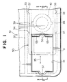
- Fig. 5 shows inner sides of separated upper and lower shells which form the cartridge 1
- Fig. 6 shows a reverse side of the cartridge 1.
- Each shell is provided with each of openings 7 and 8 and an arrangement is made so that floppy disk (media) 4 inside may be seen through these openings 7 and 8.
- openings 7 and 8 are usually covered by shutter 5 which is made of metal and has a U-shaped sectional view, causing disk 4 not to be seen.
- the shutter is located at its open position, causing the recording surface of disk 4 to be seen through the uncovered openings 7 and 8.
- disk 4 is fixed on center hub 6 will be attached on the spindle at a driver side, and is held rotatably between upper and lower shells 2 and 3.
- liner 25 on the lower shell 3, disk 4 and liner 24 on upper shell 2 are pressed against rib 12 on upper shell 2 by lifter 11 which is fixed on lower shell 3 at the position of 11a, which improves not only the rubbing between disk and liner (i.e. cleaning of disk) but also the contact area where the liner (24, in particular) and disk 4 rub each other in a relatively broader area.
- 24a, 24b, 25a, and 25b in the figure represent the area where liners are glued on the shells.
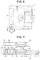
- write-protector 30 is provided at the position corresponding to the corner of each of upper and lower shells. Namely, protruded stripe portions 31 and 32 for the purpose of a guide are formed at aforesaid corners of upper and lower shells respectively. Between protruded stripes 32 on lower shell 3, there are arranged two pairs of stopper claws 33 and 34, each pair of stopper claws facing each other. These stopper claws regulate the position of write-protector 30 in its sliding direction (the direction of 35 in Fig. 5 and Fig. 6). Further, write-protector 30 is provided, on its pair of arms 38 and 39, with small protrusions 36 and 37 which engage with aforesaid stopper claws 33 and 34. Fig.
- FIG. 7 shows an enlarged sectional view taken on line VII - VII in Fig. 5 wherein embossed portion 40 provided on the external surface of write-protector 30 is inserted in opening 41 of a rectangular shape on lower shell 3 and both arms 38 and 39 are located, within aforesaid protruded stripes 32, at the positions between stopper claws 33 and 34 and protrusion 42 in a shape of a small cylinder. Then, disk 4 fixed on center hub 6 is assembled into lower shell 3, and upper shell 2 is welded onto lower shell 3 at predetermined spots on the shell and finally, shutter 5 and a spring therefor (not illustrated) are attached to finish assembling the cartridge 1.
- Write-protector 30 to be provided in cartridge 1 assembled in aforesaid manner is arranged so that it may slide in the direction marked with arrow 35, and under the condition that small protrusions 36 and 37 are engaged with claws 33, opening 43 on upper shell 2 is covered with write-protector 30 to generate the writable condition.
- opening 43 is uncovered to generate the impossible condition for writing, thus it is possible to avoid an accidental erasure.
- Such selection for sliding position of write-protector 30 may be made by forcing the write-protector to move after releasing, by means of a pin inserted from the outside of a cartridge, the engagement between claws 33/34 and small protrusions 36/37.
- Aforesaid write-protector 30 is arranged in lower shell 3 in the manner mentioned above and it never moves out of the shell because its movement is restricted in two directions, one is its sliding direction 35 and the other is the direction 44 toward the outside of a cartridge (outside of lower shell 3).
- write protector 30 easily moves out in the direction marked with arrow 45 (i.e. toward the inside of a cartridge in the direction of its thickness) because the write-protector is simply inserted in lower shell 3.
- write-protector 30 tends to come out of the shell, causing its positional deviation, its coming off and its dropping, which is extremely problematic.
- An object of the invention is to offer a magnetic disk cartridge of a type which causes its write-protector not to deviate, not to come off and not to drop.
- the invention relates to a magnetic disk cartridge provided with a write-protector arranged on a main body of the cartridge, wherein an engagement (e.g. fitting) means that causes aforesaid main body of the cartridge and aforesaid write-protector to engage (e.g. to fit) each other is provided so that aforesaid write-protector may not be moved toward the inner side of the cartridge in the direction of the thickness of the cartridge.
- an engagement e.g. fitting
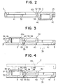
- Figs. 1 - 4 show an example of the invention, wherein Fig. 1 is an enlarged back side view of a key portion of a cartridge, Fig. 2 is a sectional view taken on line II - II in Fig. 1, Fig. 3 is a sectional view of the aforesaid key portion (sectional view in Fig. 2 turned upside down and reversed in the opposite direction) and Fig. 4 is a sectional view taken on line IV - IV in Fig. 1 similar to Fig. 3.
- Figs. 5 - 7 show a conventional example wherein Fig. 5 shows a plan view of inner surface of each of upper and lower shells separated, Fig. 6 is a back side view of the cartridge and Fig. 7 is an enlarged sectional view taken on line VII - VII in Fig. 5.
- Figs. 1 - 4 show the key portions of 3.5-inch floppy disk cartrdge 51 in the example of the invention.
- Fig. 1 is an enlarged back side view of a part corresponding in position to a location (namely, a corner portion of lower shell 3) where a write-protector is attached on the cartridge shown in Fig. 6.
- Fig. 2 is a sectional view taken on line II - II in Fig. 1 and it shows the lower shell only.
- the write-protector shown with an imaginary line in the figure has, as stated above, a pair of arms 38 and 39 having at their tips small protrusions 36 and 37 which are engaged with stopper claws 33 and 34 of lower shell 3 respectively, and is mounted, as stated above, on the inner side of protruded stripe 32 of lower shell 3.
- upper shell 2 which is not illustrated has opening 43 shown in Figs. 5 and 6 at the same position and is welded onto lower shell 3.
- step 52 is formed at the location of a shorter side on the side of protrusion 42 of opening 41 to where protector 50 is to be attached on lower shell 3, flange portion 53 slightly protruded is provided in opening 41.
- Fitting portion 33 having concaved portion 54 that engages with flange portion 53 in a sandwich style as shown in Figs. 3 and 4 is provided on the side of protector 50 corresponding to flange portion 53.
- Figs. 3 and 4 show the sectional view of Fig. 2 turned upside down and reversed in the opposite direction wherein the inside surface of lower shell 3 faces upward and protector 50 is shown with a solid line.
- protector 50 does not deviate toward the outside 45 (upward direction in Figs.
- the structure for fitting between protector 50 and lower shell 3 does not need to be limited to the foregoing and the location for the fitting may further be changed to the shorter side on the opposing side of opening 41.
- the fitting portion 55 it is possible to form the protrusion that obstructs, by catching flange portion 53, the movement of protector 50 when a force upward in Fig. 4 is applied on the protector 50, without having aforesaid sandwich type engagement that sandwiches the flange portion 53.
- aforesaid protector 50 may be provided at two locations (for 2-megabyte use) on the cartridge instead of a single location.
- the write-protector does not deviate, does not come off or does not drop accidentally any longer during the assembly process, which prevents the suspension of assembly line operation or resetting and further avoids the reduction of the yield caused by the parts missing.
Landscapes
- Engineering & Computer Science (AREA)
- Computer Security & Cryptography (AREA)
- Packaging Of Annular Or Rod-Shaped Articles, Wearing Apparel, Cassettes, Or The Like (AREA)
- Feeding And Guiding Record Carriers (AREA)
Applications Claiming Priority (2)
| Application Number | Priority Date | Filing Date | Title |
|---|---|---|---|
| JP1449488U JPH01121180U (fr) | 1988-02-04 | 1988-02-04 | |
| JP14494/88 | 1988-02-04 |
Publications (2)
| Publication Number | Publication Date |
|---|---|
| EP0327008A2 true EP0327008A2 (fr) | 1989-08-09 |
| EP0327008A3 EP0327008A3 (fr) | 1990-03-28 |
Family
ID=11862610
Family Applications (1)
| Application Number | Title | Priority Date | Filing Date |
|---|---|---|---|
| EP89101606A Withdrawn EP0327008A3 (fr) | 1988-02-04 | 1989-01-31 | Cassette à disque magnétique |
Country Status (2)
| Country | Link |
|---|---|
| EP (1) | EP0327008A3 (fr) |
| JP (1) | JPH01121180U (fr) |
Cited By (4)
| Publication number | Priority date | Publication date | Assignee | Title |
|---|---|---|---|---|
| EP0623928A1 (fr) * | 1993-05-05 | 1994-11-09 | SENTINEL, naamloze vennootschap. | Disquette et méthode et dispositif pour la fabrication de disquettes |
| WO1997007508A1 (fr) * | 1995-08-17 | 1997-02-27 | Imation Corp. | Mecanisme de protection contre l'ecriture pour disquette de stockage de donnees et son procede de fabrication |
| EP0778570A3 (fr) * | 1990-01-29 | 1997-09-24 | Dainippon Printing Co Ltd | Cassette à disque |
| US6466405B1 (en) | 1999-12-30 | 2002-10-15 | Imation Corp. | Data storage cartridge with read/write selector switch |
Citations (4)
| Publication number | Priority date | Publication date | Assignee | Title |
|---|---|---|---|---|
| GB2090226A (en) * | 1980-12-16 | 1982-07-07 | Sony Corp | Magnetic recording cassettes having an erroneous erasure preventing device |
| EP0185364A2 (fr) * | 1984-12-17 | 1986-06-25 | Sony Corporation | Cassette à disque magnétique avec un dispositif pour éviter l'effacement |
| EP0206897A2 (fr) * | 1985-06-11 | 1986-12-30 | Shape Inc. | Assemblage d'une enveloppe pour disque flexible et méthode d'assemblage |
| JPS62124685A (ja) * | 1985-11-25 | 1987-06-05 | Toshiba Corp | デイスクカセツト |
-
1988
- 1988-02-04 JP JP1449488U patent/JPH01121180U/ja active Pending
-
1989
- 1989-01-31 EP EP89101606A patent/EP0327008A3/fr not_active Withdrawn
Patent Citations (4)
| Publication number | Priority date | Publication date | Assignee | Title |
|---|---|---|---|---|
| GB2090226A (en) * | 1980-12-16 | 1982-07-07 | Sony Corp | Magnetic recording cassettes having an erroneous erasure preventing device |
| EP0185364A2 (fr) * | 1984-12-17 | 1986-06-25 | Sony Corporation | Cassette à disque magnétique avec un dispositif pour éviter l'effacement |
| EP0206897A2 (fr) * | 1985-06-11 | 1986-12-30 | Shape Inc. | Assemblage d'une enveloppe pour disque flexible et méthode d'assemblage |
| JPS62124685A (ja) * | 1985-11-25 | 1987-06-05 | Toshiba Corp | デイスクカセツト |
Non-Patent Citations (1)
| Title |
|---|
| PATENT ABSTRACTS OF JAPAN vol. 11, no. 342 (P-635)(2789) 10 November 1987, & JP-A-62 124685 (TOSHIBA CORP.) 05 June 1987, * |
Cited By (6)
| Publication number | Priority date | Publication date | Assignee | Title |
|---|---|---|---|---|
| EP0778570A3 (fr) * | 1990-01-29 | 1997-09-24 | Dainippon Printing Co Ltd | Cassette à disque |
| EP0623928A1 (fr) * | 1993-05-05 | 1994-11-09 | SENTINEL, naamloze vennootschap. | Disquette et méthode et dispositif pour la fabrication de disquettes |
| BE1007074A3 (nl) * | 1993-05-05 | 1995-03-07 | Sentinel Naamloze Vennootschap | Diskette, alsmede werkwijze en inrichting voor het vervaardigen van diskettes. |
| WO1997007508A1 (fr) * | 1995-08-17 | 1997-02-27 | Imation Corp. | Mecanisme de protection contre l'ecriture pour disquette de stockage de donnees et son procede de fabrication |
| US5748419A (en) * | 1995-08-17 | 1998-05-05 | Imation Corp. | Write protect mechanism with spring element for data storage diskette and fabrication method |
| US6466405B1 (en) | 1999-12-30 | 2002-10-15 | Imation Corp. | Data storage cartridge with read/write selector switch |
Also Published As
| Publication number | Publication date |
|---|---|
| JPH01121180U (fr) | 1989-08-16 |
| EP0327008A3 (fr) | 1990-03-28 |
Similar Documents
| Publication | Publication Date | Title |
|---|---|---|
| US6205115B1 (en) | Disc cartridge | |
| EP0336637B1 (fr) | Cassette à disque | |
| US5627707A (en) | Disk cartridge with a stop wall to engage a shutter plate projection and at least one support located between the stop wall and a cartridge side edge | |
| US5121279A (en) | Magnetic disk cartridge write/protect assembly having impact avoiding portions | |
| EP0260876A2 (fr) | Cartouche à disque | |
| US4851948A (en) | Disk cartridge with shutter biasing device | |
| KR940005567B1 (ko) | 디스크 카트리지 | |
| US5072326A (en) | Disc cartridge and shutter assembly thereof | |
| EP0327008A2 (fr) | Cassette à disque magnétique | |
| US5121277A (en) | Disc cartridge with shutter and assembling and mounting mechanism therefor | |
| JPH056629Y2 (fr) | ||
| JPH0772987B2 (ja) | デイスクカートリツジ | |
| US5195084A (en) | Disc cartridge | |
| US5081557A (en) | Magnetic disk cartridge having a cutaway portion on the front edge to prevent damage from incorrect loading | |
| JPS6141177Y2 (fr) | ||
| JPH0740420B2 (ja) | デイスクカ−トリツジ | |
| JPH0533363U (ja) | デイスクカートリツジのシヤツタースプリング用ストツパ | |
| US5136449A (en) | Shutter stop mechanism for disk cartridges | |
| JPH0233340Y2 (fr) | ||
| JPS6141175Y2 (fr) | ||
| JPS6316048Y2 (fr) | ||
| JPH0433594Y2 (fr) | ||
| JPS6141176Y2 (fr) | ||
| JP2595912Y2 (ja) | カートリッジ | |
| JPS6141168Y2 (fr) |
Legal Events
| Date | Code | Title | Description |
|---|---|---|---|
| PUAI | Public reference made under article 153(3) epc to a published international application that has entered the european phase |
Free format text: ORIGINAL CODE: 0009012 |
|
| AK | Designated contracting states |
Kind code of ref document: A2 Designated state(s): DE GB |
|
| PUAL | Search report despatched |
Free format text: ORIGINAL CODE: 0009013 |
|
| AK | Designated contracting states |
Kind code of ref document: A3 Designated state(s): DE GB |
|
| 17P | Request for examination filed |
Effective date: 19900829 |
|
| 17Q | First examination report despatched |
Effective date: 19920707 |
|
| STAA | Information on the status of an ep patent application or granted ep patent |
Free format text: STATUS: THE APPLICATION IS DEEMED TO BE WITHDRAWN |
|
| 18D | Application deemed to be withdrawn |
Effective date: 19921118 |