EP0325705A2 - Displacement-measuring apparatus - Google Patents
Displacement-measuring apparatus Download PDFInfo
- Publication number
- EP0325705A2 EP0325705A2 EP88118196A EP88118196A EP0325705A2 EP 0325705 A2 EP0325705 A2 EP 0325705A2 EP 88118196 A EP88118196 A EP 88118196A EP 88118196 A EP88118196 A EP 88118196A EP 0325705 A2 EP0325705 A2 EP 0325705A2
- Authority
- EP
- European Patent Office
- Prior art keywords
- contact
- contacts
- tracks
- actuator
- adjustable
- Prior art date
- Legal status (The legal status is an assumption and is not a legal conclusion. Google has not performed a legal analysis and makes no representation as to the accuracy of the status listed.)
- Withdrawn
Links
Images

Classifications
-
- G—PHYSICS
- G01—MEASURING; TESTING
- G01D—MEASURING NOT SPECIALLY ADAPTED FOR A SPECIFIC VARIABLE; ARRANGEMENTS FOR MEASURING TWO OR MORE VARIABLES NOT COVERED IN A SINGLE OTHER SUBCLASS; TARIFF METERING APPARATUS; MEASURING OR TESTING NOT OTHERWISE PROVIDED FOR
- G01D5/00—Mechanical means for transferring the output of a sensing member; Means for converting the output of a sensing member to another variable where the form or nature of the sensing member does not constrain the means for converting; Transducers not specially adapted for a specific variable
- G01D5/12—Mechanical means for transferring the output of a sensing member; Means for converting the output of a sensing member to another variable where the form or nature of the sensing member does not constrain the means for converting; Transducers not specially adapted for a specific variable using electric or magnetic means
- G01D5/25—Selecting one or more conductors or channels from a plurality of conductors or channels, e.g. by closing contacts
- G01D5/252—Selecting one or more conductors or channels from a plurality of conductors or channels, e.g. by closing contacts a combination of conductors or channels
-
- D—TEXTILES; PAPER
- D06—TREATMENT OF TEXTILES OR THE LIKE; LAUNDERING; FLEXIBLE MATERIALS NOT OTHERWISE PROVIDED FOR
- D06F—LAUNDERING, DRYING, IRONING, PRESSING OR FOLDING TEXTILE ARTICLES
- D06F39/00—Details of washing machines not specific to a single type of machines covered by groups D06F9/00 - D06F27/00
- D06F39/08—Liquid supply or discharge arrangements
- D06F39/087—Water level measuring or regulating devices
-
- G—PHYSICS
- G01—MEASURING; TESTING
- G01F—MEASURING VOLUME, VOLUME FLOW, MASS FLOW OR LIQUID LEVEL; METERING BY VOLUME
- G01F23/00—Indicating or measuring liquid level or level of fluent solid material, e.g. indicating in terms of volume or indicating by means of an alarm
- G01F23/14—Indicating or measuring liquid level or level of fluent solid material, e.g. indicating in terms of volume or indicating by means of an alarm by measurement of pressure
- G01F23/16—Indicating, recording, or alarm devices being actuated by mechanical or fluid means, e.g. using gas, mercury, or a diaphragm as transmitting element, or by a column of liquid
- G01F23/164—Indicating, recording, or alarm devices being actuated by mechanical or fluid means, e.g. using gas, mercury, or a diaphragm as transmitting element, or by a column of liquid using a diaphragm, bellow as transmitting element
-
- G—PHYSICS
- G01—MEASURING; TESTING
- G01F—MEASURING VOLUME, VOLUME FLOW, MASS FLOW OR LIQUID LEVEL; METERING BY VOLUME
- G01F23/00—Indicating or measuring liquid level or level of fluent solid material, e.g. indicating in terms of volume or indicating by means of an alarm
- G01F23/14—Indicating or measuring liquid level or level of fluent solid material, e.g. indicating in terms of volume or indicating by means of an alarm by measurement of pressure
- G01F23/18—Indicating, recording or alarm devices actuated electrically
- G01F23/185—Indicating, recording or alarm devices actuated electrically for discrete levels
Definitions
- the invention relates to a device for determining switching signals as a function of the respective position of two components which can be mechanically adjusted relative to one another and which are provided with switching contacts connected to circuits, for example for detecting the liquid level in a washing machine or dishwasher.
- Electromechanical level sensors of the aforementioned type are known for determining the respective liquid level in a washing machine or dishwasher.
- a switch contact is assigned to each fill level, which is important for the function of the machine and is therefore to be monitored, so that eight switch contacts are required to determine eight fill levels, for example.
- the construction and investment effort is thus considerable, and due to the large number of switch contacts, a relatively large installation space is required, and an assembly equipped with such a large number of contacts, which are often not very sensitive, is also prone to failure.
- the object of the invention is therefore to provide a device of the aforementioned type which is small in size, economical to produce and insensitive to faults, but with which a large number of liquid levels can nevertheless be reliably transmitted in an electromechanical manner. Above all, however, it is to be achieved that even very low fill levels and minimal changes in the fill quantities are to be recorded, without requiring a great deal of construction and investment.
- the one component consists of, for example, a fixedly arranged contact carrier with a plurality of contacts attached to it, preferably by means of a resilient contact tongue, and that the other component is guided so as to be displaceable relative to the contact carrier Contact plate is formed, which has differently coded contact tracks interacting with the contacts.
- the contact pressure of the contacts on the contact plate can be adjusted, for example, by means of an adjusting screw assigned to the contact plate.
- This can be accomplished in such a way that the set screws are each supported by means of a compression spring or a resilient extension, preferably at the level of the contacts on the contact tongues, or act on the contacts via permanent magnets which are arranged on the contacts tongues and have the same polarity to one another. The friction forces to be overcome during an adjustment movement of the two components can be minimized in this way.
- contact tongues in each case by means of a leaf spring fastened to the contact carrier with one end and to provide the contact tracks on one or both sides of the contact plate.
- the contact plate can be fixedly connected directly or via intermediate elements to an adjustable actuator, for example with the aid of a membrane clamped in a housing and displaceable depending on the liquid level of a washing machine or dishwasher, it being indicated that several contact plates and the with these interacting contact carriers to be arranged symmetrically to the longitudinal axis of the actuator or of the housing accommodating the latter, preferably diametrically opposite one another.
- the contact plates can be formed here by a polygonal, centrally arranged extension of the actuator, to which the contact tracks are attached to surfaces that are preferably opposite one another, and the contacts that interact with them can be arranged in an adjustable manner in a housing that accommodates the actuator.
- a device for determining switching signals in which one of the components which can be adjusted relative to one another consists of a contact carrier provided with contacts and the other of the components consists of a contact plate provided with differently coded contact tracks, it is possible to do so on a very small size Space to accommodate an extremely large number of switch contacts and thus reliably monitor a large number of fill levels or movement processes dependent on other manipulated variables in an electro-mechanical manner.
- the coding of the contact paths results in an increasing number of usable ones, which increases exponentially Switching signals are available, with three contact tracks attached to a contact plate, for example eight signals. And each additional contact path doubles the number of signals that can be evaluated. An extremely sensitive monitoring of an adjustment path can thus be accomplished without great construction and investment expenditure.
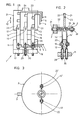
- the device shown in Figures 1 to 3 and designated 1 is used to determine switching signals in an electromechanical manner depending on the position of two relatively adjustable components 11 and 21, which are connected by means of control lines 4, 5 and 6 to switching elements, not shown.
- the components 11 and 21 are installed in a housing 2 provided with a pressure medium connection 3, in which an actuator acted upon by the pressure medium supplied, for example by the liquid of a washing machine or dishwasher, is inserted, which is thus adjustable depending on the respective liquid level .
- the component 11 here consists of a stationary contact carrier 12 which has three contacts 13, 15 and 17.
- the contacts 13, 15 and 17 are held on contact tongues 14, 16 and 18, which are each fastened to the contact carrier 12 by means of a clamping screw 19 penetrating a slot 20.
- the contact tracks 23, 24 and 25 are coded differently, so that by means of the contacts 13, 15 and 17 and the contact tracks 23, 24 and 25 eight different switching signals can be supplied to the switching elements via the control lines 4, 5 and 6 and thus also small adjustment movements of the contact plate 22 can be determined and monitored.
- the switching tongues 14, 16 and 18, which consist of leaf springs clamped at one end, are each provided with an adjusting screw 30 which is in threaded bores 29 of the contact carrier 12 are held, adjustable in the longitudinal direction.
- the switching tongues 14, 16 and 18 are provided with the longitudinal slots 20 which are penetrated by the clamping screws 19 to which the control lines 4, 5 and 6 are also connected.
- a set screw 31 or 33 held in the housing 2 is provided, either via a compression spring 32, as shown in the left half of FIG. 2, or as shown in FIG the right half of Figure 2, via two on the adjusting screw 33 and the switching tongue 14 'attached to the same pole arranged permanent magnets 34 and 35 act on the switching tongues 14 and 14'.
- the contact plate 22, as can also be seen in FIG. 2, can be equipped on both sides with conductor tracks, on which the contacts 13 ..., 13 '... bear. It is also expedient according to the embodiment of Figure 3, two contact carriers 12, 12 'and interacting with them contact plates 22, 22' diametrically to the longitudinal axis of the housing 2 to be arranged opposite each other, since in this way there is symmetry and thus no tilting forces occur.
- a membrane 43 is clamped in a housing 42, which acts on an actuator 45 designed as a pressure plate and which is assigned a pressure chamber 44 for a pressure medium to be supplied.
- the actuator 45 is in this case equipped with a central projection 46 which is designed as a polygon and which forms the adjustable component 61.
- Contact surfaces provided with coded contact tracks 63 are arranged on mutually opposite surfaces of the projection 46, which interact with a contact 53 formed on the fixed component 51 as a contact carrier 52.
- the contacts 53 are each held in turn by a contact tongue 54.
- the contact carrier 52 can be aligned with the contact plate 62 by means of a set screw 55, and the contact pressure of the contacts 53 and the contact plates 62 can also be set with the aid of a further set screw 56, which acts on a resilient extension 57 formed on the contact tongue 54.
- the device 41 is effective in the same way as the device according to FIGS. 1 to 3, so that a large number of evaluable signals can be determined with the aid of the coded contact tracks 63 and the contacts 53 and the adjustment path of the membrane 43 can be carefully monitored.
Landscapes
- Physics & Mathematics (AREA)
- General Physics & Mathematics (AREA)
- Engineering & Computer Science (AREA)
- Textile Engineering (AREA)
- Fluid Mechanics (AREA)
- Washing And Drying Of Tableware (AREA)
- Push-Button Switches (AREA)
- Measurement Of Length, Angles, Or The Like Using Electric Or Magnetic Means (AREA)
Abstract
Description
Die Erfindung bezieht sich auf eine Einrichtung zur Ermittlung von Schaltsignalen in Abhängigkeit von der jeweiligen Lage zweier relativ zueinander mechanisch verstellbarer Bauteile, die mit an Stromkreise angeschlossenen Schaltkontakten versehen sind, beispielsweise zur Erfassung des Flüssigkeitsstandes in einer Wasch- oder Geschirrspülmaschine.The invention relates to a device for determining switching signals as a function of the respective position of two components which can be mechanically adjusted relative to one another and which are provided with switching contacts connected to circuits, for example for detecting the liquid level in a washing machine or dishwasher.
Zur Bestimmung des jeweiligen Flüssigkeitsstandes in einer Wasch- oder Geschirrspülmaschine sind elektromechanische Füllstandssensoren der vorgenannten Art bekannt. Jedem Füllstand, der für die Funktion der Maschine von Bedeutung und somit zu überwachen ist, ist jeweils ein Schaltkontakt zugeordnet, so daß, um beispielsweise acht Füllstände zu ermitteln, auch acht Schaltkontakte erforderlich sind. Der Bau- und Investitionsaufwand ist somit erheblich, auch wird durch die Vielzahl der Schaltkontakte ein verhältnismäßig großer Bauraum benötigt und ein mit einer derartigen Vielzahl von oftmals nicht sehr empfindlichen Kontakten bestücktes Aggregat ist auch störanfällig.Electromechanical level sensors of the aforementioned type are known for determining the respective liquid level in a washing machine or dishwasher. A switch contact is assigned to each fill level, which is important for the function of the machine and is therefore to be monitored, so that eight switch contacts are required to determine eight fill levels, for example. The construction and investment effort is thus considerable, and due to the large number of switch contacts, a relatively large installation space is required, and an assembly equipped with such a large number of contacts, which are often not very sensitive, is also prone to failure.
Aufgabe der Erfindung ist es daher, eine Einrichtung der vorgenannten Gattung zu schaffen, die klein baut, wirtschaftlich herzustellen und störunempfindlich ist, mit der aber dennoch eine große Anzahl von Flüssigkeitsständen auf elektromechanische Weise zuverlässig zu übermitteln ist. Vor allem aber soll erreicht werden, daß auch sehr niedere Füllstände und minimale Veränderungen der Füllmengen zu erfassen sind, ohne daß es dazu eines großen Bau- und Investitionsaufwandes bedarf.The object of the invention is therefore to provide a device of the aforementioned type which is small in size, economical to produce and insensitive to faults, but with which a large number of liquid levels can nevertheless be reliably transmitted in an electromechanical manner. Above all, however, it is to be achieved that even very low fill levels and minimal changes in the fill quantities are to be recorded, without requiring a great deal of construction and investment.
Gemäß der Erfindung wird dies bei einer Einrichtung der eingangs genannten Art dadurch erreicht, daß das eine Bauteil aus einem beispielsweise ortsfest angeordneten Kontaktträger mit mehreren an diesem vorzugsweise mittels jeweils einer federnden Kontaktzunge angebrachter Kontakte besteht und daß das andere Bauteil als relativ zu dem Kontaktträger verschiebbar geführte Kontaktplatte ausgebildet ist, die unterschiedlich kodierte mit den Kontakten zusammenwirkende Kontaktbahnen aufweist.According to the invention, this is achieved in a device of the type mentioned above in that the one component consists of, for example, a fixedly arranged contact carrier with a plurality of contacts attached to it, preferably by means of a resilient contact tongue, and that the other component is guided so as to be displaceable relative to the contact carrier Contact plate is formed, which has differently coded contact tracks interacting with the contacts.
Sehr vorteilhaft ist es hierbei, die Kontakte des Kontaktträgers einzeln, beispielsweise mittels Stellschrauben, in Richtung der Kontaktbahnen verstellbar anzuordnen, so daß deren Ausrichtung auf einfache Weise vorzunehmen ist.It is very advantageous here to arrange the contacts of the contact carrier individually, for example by means of adjusting screws, in the direction of the contact tracks so that their alignment can be carried out in a simple manner.
Ferner ist es zweckmäßig, wenn die Anpreßkraft der Kontakte an der Kontaktplatte beispielsweise jeweils mittels einer diesen zugeordneten Stellschraube einstellbar ist. Dies kann in der Art bewerkstelligt werden, daß die Stellschrauben jeweils mittels einer Druckfeder oder eines federnden Ansatzes vorzugsweise in Höhe der Kontakte an den Kontaktzungen abgestützt sind oder über an diesen und den Kontaktzungen angebrachter, gleichpolig zueinander angeordneter Permanentmagnete auf die Kontakte einwirken. Die bei einer Verstellbewegung der beiden Bauteile zu überwindenden Reibungskräfte können auf diese Weise minimiert werden.Furthermore, it is expedient if the contact pressure of the contacts on the contact plate can be adjusted, for example, by means of an adjusting screw assigned to the contact plate. This can be accomplished in such a way that the set screws are each supported by means of a compression spring or a resilient extension, preferably at the level of the contacts on the contact tongues, or act on the contacts via permanent magnets which are arranged on the contacts tongues and have the same polarity to one another. The friction forces to be overcome during an adjustment movement of the two components can be minimized in this way.
Angebracht ist es auch, die Kontaktzungen jeweils durch eine mit einem Ende an dem Kontaktträger befestigten Blattfeder zu bilden und die Kontaktbahnen auf einer oder beiden Seiten der Kontaktplatte vorzusehen.It is also appropriate to form the contact tongues in each case by means of a leaf spring fastened to the contact carrier with one end and to provide the contact tracks on one or both sides of the contact plate.
Nach einer vorteilhaften Ausgestaltung kann die Kontaktplatte unmittelbar oder über Zwischenglieder mit einem verstellbaren beispielsweise mit Hilfe einer in einem Gehäuse eingespannten und in Abhängigkeit von dem Flüssigkeitsstand einer Wasch- oder Geschirrspülmaschine beaufschlagten Membran verschiebbaren Stellglied fest verbunden werden, wobei es angezeigt ist, mehrere Kontaktplatten und die mit diesen jeweils zusammenwirkenden Kontaktträger symmetrisch zur Längsachse des Stellgliedes bzw. des dieses aufnehmenden Gehäuses, vorzugsweise diametral einander gegenüberliegend, anzuordnen. Außerdem können hierbei die Kontaktplatten durch einen als Mehrkant gestalteten zentrisch angeordneten Ansatz des Stellgliedes gebildet sein, an dem die Kontaktbahnen an vorzugsweise einander gegenüberliegenden Flächen angebrachtsind, und die mit diesen zusammenwirkenden Kontakte einstellbar in einem das Stellglied aufnehmenden Gehäuse angeordnet sein.According to an advantageous embodiment, the contact plate can be fixedly connected directly or via intermediate elements to an adjustable actuator, for example with the aid of a membrane clamped in a housing and displaceable depending on the liquid level of a washing machine or dishwasher, it being indicated that several contact plates and the with these interacting contact carriers to be arranged symmetrically to the longitudinal axis of the actuator or of the housing accommodating the latter, preferably diametrically opposite one another. In addition, the contact plates can be formed here by a polygonal, centrally arranged extension of the actuator, to which the contact tracks are attached to surfaces that are preferably opposite one another, and the contacts that interact with them can be arranged in an adjustable manner in a housing that accommodates the actuator.
Wird eine Einrichtung zur Ermittlung von Schaltsignalen gemäß der Erfindung ausgebildet, in dem das eine der relativ zueinander verstellbaren Bauteile aus einem mit Kontakten versehenen Kontaktträger und das andere der Bauteile aus einer mit unterschiedlich kodierten Kontaktbahnen versehenen Kontaktplatte bestehen, so ist es möglich, auf sehr kleinem Bauraum eine äußerst große Vielzahl von Schaltkontakten unterzubringen und somit eine Vielzahl von Füllständen oder von anderen Stellgrößen abhängige Bewegungsvorgänge auf elektro-mechanische Weise zuverlässig zu überwachen. Durch die Kodierung der Kontaktbahnen steht nämlich eine exponentiell zu diesen ansteigende Anzahl von verwertbaren Schaltsignalen zur Verfügung, bei drei an einer Kontaktplatte angebrachten Kontaktbahnen beispielsweise acht Signale. Und durch jede weitere Kontaktbahn wird die Anzahl der auswertbaren Signale verdoppelt. Ohne großen Bau- und Investitionsaufwand kann somit eine äußerst feinfühlige Überwachung eines Verstellweges bewerkstelligt werden.If a device for determining switching signals is designed according to the invention, in which one of the components which can be adjusted relative to one another consists of a contact carrier provided with contacts and the other of the components consists of a contact plate provided with differently coded contact tracks, it is possible to do so on a very small size Space to accommodate an extremely large number of switch contacts and thus reliably monitor a large number of fill levels or movement processes dependent on other manipulated variables in an electro-mechanical manner. The coding of the contact paths results in an increasing number of usable ones, which increases exponentially Switching signals are available, with three contact tracks attached to a contact plate, for example eight signals. And each additional contact path doubles the number of signals that can be evaluated. An extremely sensitive monitoring of an adjustment path can thus be accomplished without great construction and investment expenditure.
Des weiteren ist die Störanfälligkeit der vorschlagsgemäß ausgebildeten Einrichtung, da die Anzahl der zu überwachenden Schaltkontakte erheblich reduziert ist, gering, auch wird für diese nur ein geringer Bauraum benötigt. Vor allem aber ist von Vorteil, daß die durch die Schaltkontakte hervorgerufenen Reibungskräfte minimiert werden können, so daß auch geringe Druckhöhen und Druckveränderungen zuverlässig zu ermitteln und zu überwachen sind. Bei einfacher Handhabung ist somit eine Einrichtung geschaffen, die vielseitig zur Kraft- bzw. Verstellwegmessung einsetzbar ist.Furthermore, since the number of switch contacts to be monitored is considerably reduced, the susceptibility to malfunction of the device designed according to the proposal is low, and only a small installation space is required for these. Above all, however, it is advantageous that the frictional forces caused by the switching contacts can be minimized, so that even low pressure levels and pressure changes can be reliably determined and monitored. With simple handling, a device is thus created which can be used in a versatile manner for measuring force or displacement.
In der Zeichnung sind zwei Ausführungsbeispiele der gemäß der Erfindung ausgebildeten elektromechanischen Verstellwegmeßeinrichtung dargestellt, die nachfolgend im einzelnen erläutert sind. Hierbei zeigen:
- Figur 1 die aus einem Kontaktträger und aus einer mit Kontaktbahnen versehenen verstellbar angeordneten Kontaktplatte bestehende Einrichtung, in Vorderansicht,
Figur 2 die Einrichtung nach Figur 1 in einer Seitenansicht, in unterschiedlichen AusführungsvariantenFigur 3 die gegenüberliegende Anordnung zweier Einrichtungen nach Figur 1 in einem Gehäuse, in Draufsicht undFigur 4 eine andersartige Ausgestaltung einer Einrichtung, in einem Axialschnitt.
- 1 shows the device consisting of a contact carrier and an adjustable contact plate provided with contact tracks, in front view,
- Figure 2 shows the device of Figure 1 in a side view, in different versions
- Figure 3 shows the opposite arrangement of two devices according to Figure 1 in a housing, in plan view and
- Figure 4 shows a different design of a device, in an axial section.
Die in den Figuren 1 bis 3 dargestellte und mit 1 bezeichnete Einrichtung dient zur Ermittlung von Schaltsignalen auf elektromechanische Weise in Abhängigkeit von der Lage zweier relativ zueinander verstellbarer Bauteile 11 und 21, die mittels Steuerleitungen 4, 5 und 6 an nicht gezeigte Schaltelemente angeschlossen sind. Die Bauteile 11 und 21 sind hierbei in einem mit einem Druckmittelanschluß 3 versehenen Gehäuse 2 eingebaut, in dem ein von dem zugeführten Druckmittel, beispielsweise von der Flüssigkeit einer Wasch- oder Geschirrspülmaschine beaufschlagtes Stellglied eingesetzt ist, das somit in Abhängigkeit von dem jeweiligen Flüssigkeitsstand verstellbar ist.The device shown in Figures 1 to 3 and designated 1 is used to determine switching signals in an electromechanical manner depending on the position of two relatively
Das Bauteil 11 besteht hierbei aus einem ortsfest angeordneten Kontaktträger 12, der drei Kontakte 13, 15 und 17 aufweist. Die Kontakte 13, 15 und 17 sind hierbei an Kontaktzungen 14, 16 und 18 gehalten, die jeweils mittels einer einen Schlitz 20 durchgreifenden Klemmschraube 19 an dem Kontaktträger 12 befestigt sind.The
Das mit dem Kontaktträger 12 zusammenwirkende in Richtung des Pfeiles 10 durch das Stellglied verschiebbare Bauteil 21 besteht aus einer Kontaktplatte 22, die mit den Kontakten 13, 15 und 17 zugeordneten Kontaktbahnen 23, 24 und 25 versehen ist. Die Kontaktbahnen 23, 24 und 25 sind unterschiedlich kodiert, so das mittels der Kontakte 13, 15 und 17 sowie den Kontaktbahnen 23, 24 und 25 acht unterschiedliche Schaltsignale über die Steuerleitungen 4, 5 und 6 den Schaltelementen zugeführt werden können und somit auch kleine Verstellbewegungen der Kontaktplatte 22 feststellbar und zu überwachen sind.The
Um die Kontakte 13, 15 und 17 auf einfache Weise auf die Kontaktbahnen 23, 24 und 25 ausrichten zu können, sind die Schaltzungen 14, 16 und 18, die aus an einem Ende eingespannten Blattfedern bestehen, jeweils mit einer Stellschraube 30, die in Gewindebohrungen 29 des Kontaktträgers 12 gehalten sind, in Längsrichtung verstellbar. Die Schaltzungen 14, 16 und 18 sind dazu mit den von den Klemmschrauben 19 an denen auch die Steuerleitungen 4, 5 und 6 angeschlossen sind, durchgriffenen Längsschlitze 20 ausgestattet.In order to be able to align the
Des weiteren ist die Anpreßkraft, mit der die Kontakte 13, 15 und 17 an der Kontaktplatte 22 anliegen, einstellbar, so daß die bei einer Verstellbewegung auftretenden Reibungskräfte minimiert werden können. Dazu ist, wie dies der Figur 2 entnommen werden kann, jeweils eine in dem Gehäuse 2 gehaltene Stellschraube 31 bzw. 33 vorgesehen, die entweder über eine Druckfeder 32, wie dies in der linken Hälfte der Figur 2 gezeigt ist, oder gemäß der Darstellung in der rechten Hälfte der Figur 2, über zwei an der Stellschraube 33 und der Schaltzunge 14′ angebrachte gleichpolig zueinander angeordnete Permanentmagnete 34 und 35 auf die Schaltzungen 14 bzw. 14′ einwirken.Furthermore, the contact pressure with which the
Die Kontaktplatte 22 kann, wie dies ebenfalls der Figur 2 zu entnehmen ist, beidseitig mit Leiterbahnen bestückt sein, an denen die Kontakte 13 ..., 13′ ... anliegen. Auch ist es gemäß der Ausführungsform nach Figur 3 zweckmäßig, zwei Kontaktträger 12, 12′ und mit diesen zusammenwirkende Kontaktplatten 22, 22′ diametral zur Längsachse des Gehäuses 2 einander gegenüberliegend anzuordnen, da auf diese Weise eine Symmetrie gegeben ist und somit keine Kippkräfte auftreten.The
Bei der in Figur 4 dargestellten Einrichtung 41 ist in einem Gehäuse 42 eine Membran 43 eingespannt, die auf ein als Druckplatte ausgebildetes Stellglied 45 einwirkt und der ein Druckraum 44 für ein zuzuführendes Druckmittel zugeordnet ist. Das Stellglied 45 ist hierbei mit einem als Mehrkant ausgebildeten zentrischen Ansatz 46, der das verstellbare Bauteil 61 bildet, ausgestattet. Auf einander gegenüberliegnden Flächen des Ansatzes 46 sind mit kodierten Kontaktbahnen 63 versehene Kontaktplatten angeordnet, die mit einem an dem ortsfesten Bauteil 51 als Kontaktträger 52 ausgebildete Kontakte 53 zusammenwirken. Die Kontakte 53 sind jeweils wiederum durch eine Kontaktzunge 54 gehalten.In the
Der Kontaktträger 52 ist mittels einer Stellschraube 55 auf die Kontaktplatte 62 ausrichtbar, auch ist die Anpreßkraft der Kontakte 53 und der Kontaktplatten 62 mit Hilfe einer weiteren Stellschraube 56, die auf einen an der Kontaktzunge 54 angeformten federnden Ansatz 57 einwirkt, einstellbar.The
Die Einrichtung 41 ist in gleicher Weise wirksam wie die Einrichtung nach den Figuren 1 bis 3, so daß mit Hilfe der kodierten Kontaktbahnen 63 und der Kontakte 53 eine Vielzahl von auswertbaren Signalen zu ermitteln und der Verstellweg der Membran 43 feinfühlig zu überwachen ist.The
Claims (10)
dadurch gekennzeichnet,
daß das eine Bauteil (11; 51) aus einem beispielsweise orstfest angeordneten Kontaktträger (12; 52) mit mehreren an diesem vorzugsweise mittels jeweils einer federnden Kontaktzunge (14, 16, 18; 54) angebrachter Kontakte (13, 15, 17; 53) besteht und daß das andere Bauteil (21; 61) als relativ zu dem Kontaktträger (12; 52) verschiebbar geführte Kontaktplatte (22; 62) ausgebildet ist, die unterschiedlich kodierte mit den Kontakten (13, 15, 17; 53) zusammenwirkende Kontaktbahnen (23, 24, 25; 63) aufweist.1. Device for determining switching signals as a function of the respective position of two mechanically adjustable components which are provided with switching contacts connected to circuits, for example for detecting the liquid level in a washing machine or dishwasher,
characterized,
that one component (11; 51) consists of, for example, a fixedly arranged contact carrier (12; 52) with several contacts (13, 15, 17; 53) attached to it, preferably by means of a resilient contact tongue (14, 16, 18; 54) and that the other component (21; 61) is designed as a contact plate (22; 62) which is displaceably guided relative to the contact carrier (12; 52) and which has differently coded contact tracks (13, 15, 17; 53) which interact with the contacts (13, 15, 17; 53) 23, 24, 25; 63).
dadurch gekennzeichnet,
daß die Kontakte (13, 15, 17; 53) des Kontaktträgers (12; 52) einzeln, beispielsweise mittels Stellschrauben (30; 55), in Richtung der Kontaktbahnen (23, 24, 25; 63) verstellbar angeordnet sind.2. Device according to claim 1,
characterized,
that the contacts (13, 15, 17; 53) of the contact carrier (12; 52) are individually adjustable, for example by means of adjusting screws (30; 55), in the direction of the contact tracks (23, 24, 25; 63).
dadurch gekennzeichnet,
daß die Anpreßkraft der Kontakte (13, 15, 17; 53) an der Kontaktplatte (22; 62) beispielsweise jeweils mittels einer diesen zugeordneten Stellschraube (31; 33; 56) einstellbar ist.3. Device according to claim 1 or 2,
characterized,
that the contact pressure of the contacts (13, 15, 17; 53) on the contact plate (22; 62) can be set, for example, in each case by means of an adjusting screw (31; 33; 56) assigned to them.
dadurch gekennzeichnet,
daß die Stellschrauben (31; 56) jeweils mittels einer Druckfeder (32) oder eines federnden Ansatzes (57) vorzugsweise in Höhe der Kontakte (13, 15, 17) an den Kontaktzungen (14, 16, 18; 54) abgestützt sind.4. Device according to claim 3,
characterized,
that the set screws (31; 56) are each supported by means of a compression spring (32) or a resilient extension (57), preferably at the level of the contacts (13, 15, 17) on the contact tongues (14, 16, 18; 54).
dadurch gekennzeichnet,
daß die Stellschrauben (33) über an diesen und den Kontaktzungen (14′) angebrachter, gleichpolig zueinander angeordneter Permanentmagnete (34, 35) auf die Kontakte (13′) einwirken.5. Device according to claim 3,
characterized,
that the setscrews (33) act on the contacts (13 ') via the permanent magnets (34, 35) which are attached to the latter and the contact tongues (14') and have the same poles.
dadurch gekennzeichnet,
daß die Kontaktzungen (14, 16, 18; 54) jeweils durch eine mit einem Ende an dem Kontaktträger (12; 52) befestigten Blattfeder gebildet sind.6. Device according to one or more of claims 1 to 5,
characterized,
that the contact tongues (14, 16, 18; 54) are each formed by a leaf spring fastened at one end to the contact carrier (12; 52).
dadurch gekennzeichnet,
daß die Kontaktbahnen (23, 24, 25) auf einer oder beiden Seiten der Kontaktplatte (22) angebracht sind.7. Device according to one or more of claims 1 to 6,
characterized,
that the contact tracks (23, 24, 25) are attached to one or both sides of the contact plate (22).
dadurch gekennzeichnet,
daß die Kontaktplatte (63) unmittelbar oder über Zwischenglieder (Ansatz 46) mit einem verstellbaren, beispielsweise mit Hilfe einer in einem Gehäuse (42) eingespannten und in Abhängigkeit von dem Flüssigkeitsstand einer Wasch- oder Geschirrspülmaschine beaufschlagten Membran (43) verschiebbaren Stellglied (45) verbunden ist.8. Device according to one or more of claims 1 to 7,
characterized,
that the contact plate (63) is directly or via intermediate elements (attachment 46) with an adjustable actuator (45) which can be displaced, for example with the aid of a membrane (43) clamped in a housing (42) and acted upon as a function of the liquid level of a washing machine or dishwasher. connected is.
dadurch gekennzeichnet,
daß mehrere Kontaktplatten (22, 22′; 62) und die mit diesen jeweils zusammenwirkenden Kontaktträger (12, 12′; 52) symmetrisch zur Längsachse des Stellgliedes (45) bzw. des dieses aufnehmenden Gehäuses (2; 42) vorzugsweise diametral einander gegenüberliegend, angeordnet sind.9. Device according to claim 8,
characterized,
that several contact plates (22, 22 '; 62) and the contact carriers (12, 12'; 52) interacting with them in each case symmetrically to the longitudinal axis of the actuator (45) or of the housing (2; 42) accommodating them, preferably diametrically opposite one another, are arranged.
dadurch gekennzeichnet
daß die Kontaktplatten (62) durch einen als Mehrkant gestalteten zentrisch angeordneten Ansatz (46) des Stellgliedes (45) gebildet sind, an dem die Kontaktbahnen (63) an vorzugsweise einander gegenüberliegenden Flächen angebracht sind, und daß die mit diesen zusammenwirkenden Kontakte (53) einstellbar (Stellschrauben 55, 56) in einem das Stellglied (45) aufnehmenden Gehäuse (42) angeordnet sind.10. Device according to claim 8,
characterized
that the contact plates (62) are formed by a centrally arranged projection (46) of the actuator (45) designed as a polygon, on which the contact tracks (63) are attached to preferably opposite surfaces, and that the contacts (53) interacting with them adjustable (set screws 55, 56) in a housing (42) accommodating the actuator (45).
Applications Claiming Priority (2)
| Application Number | Priority Date | Filing Date | Title |
|---|---|---|---|
| DE3801899A DE3801899A1 (en) | 1988-01-23 | 1988-01-23 | ADJUSTMENT MEASURING DEVICE |
| DE3801899 | 1988-01-23 |
Publications (2)
| Publication Number | Publication Date |
|---|---|
| EP0325705A2 true EP0325705A2 (en) | 1989-08-02 |
| EP0325705A3 EP0325705A3 (en) | 1990-12-27 |
Family
ID=6345830
Family Applications (1)
| Application Number | Title | Priority Date | Filing Date |
|---|---|---|---|
| EP19880118196 Withdrawn EP0325705A3 (en) | 1988-01-23 | 1988-11-02 | Displacement-measuring apparatus |
Country Status (2)
| Country | Link |
|---|---|
| EP (1) | EP0325705A3 (en) |
| DE (1) | DE3801899A1 (en) |
Cited By (1)
| Publication number | Priority date | Publication date | Assignee | Title |
|---|---|---|---|---|
| EP0671604A1 (en) * | 1994-03-10 | 1995-09-13 | Deutsche Thomson-Brandt Gmbh | Device for transforming a mechanical quantity into an electrical quantity |
Families Citing this family (1)
| Publication number | Priority date | Publication date | Assignee | Title |
|---|---|---|---|---|
| DE4241242C2 (en) * | 1992-12-08 | 1995-01-19 | Honeywell Bv | Electrical condition sensor |
Citations (4)
| Publication number | Priority date | Publication date | Assignee | Title |
|---|---|---|---|---|
| US3207871A (en) * | 1961-08-14 | 1965-09-21 | Therm Inc | Digital indicating pressure gage |
| US3352983A (en) * | 1965-06-29 | 1967-11-14 | Controls Co Of America | Pressure switch and electrical switch therefor |
| EP0017453A1 (en) * | 1979-04-02 | 1980-10-15 | Eaton Corporation | Washing appliance and liquid level sensing means therefor |
| US4892985A (en) * | 1988-01-29 | 1990-01-09 | Aisin Seiki Kabushiki Kaisha | Vacuum responsive multicontact switch |
-
1988
- 1988-01-23 DE DE3801899A patent/DE3801899A1/en not_active Withdrawn
- 1988-11-02 EP EP19880118196 patent/EP0325705A3/en not_active Withdrawn
Patent Citations (4)
| Publication number | Priority date | Publication date | Assignee | Title |
|---|---|---|---|---|
| US3207871A (en) * | 1961-08-14 | 1965-09-21 | Therm Inc | Digital indicating pressure gage |
| US3352983A (en) * | 1965-06-29 | 1967-11-14 | Controls Co Of America | Pressure switch and electrical switch therefor |
| EP0017453A1 (en) * | 1979-04-02 | 1980-10-15 | Eaton Corporation | Washing appliance and liquid level sensing means therefor |
| US4892985A (en) * | 1988-01-29 | 1990-01-09 | Aisin Seiki Kabushiki Kaisha | Vacuum responsive multicontact switch |
Cited By (1)
| Publication number | Priority date | Publication date | Assignee | Title |
|---|---|---|---|---|
| EP0671604A1 (en) * | 1994-03-10 | 1995-09-13 | Deutsche Thomson-Brandt Gmbh | Device for transforming a mechanical quantity into an electrical quantity |
Also Published As
| Publication number | Publication date |
|---|---|
| DE3801899A1 (en) | 1989-08-03 |
| EP0325705A3 (en) | 1990-12-27 |
Similar Documents
| Publication | Publication Date | Title |
|---|---|---|
| AT390295B (en) | ELECTRICAL CONTACT DEVICE FOR A LOCKING CYLINDER WITH AN ELECTRONIC / MECHANICAL KEY | |
| EP1891494B1 (en) | Actuating device having means for blocking movements | |
| DE2844538C2 (en) | Output and registration device for food and drinks in the catering industry | |
| WO2008014873A1 (en) | Switch module | |
| EP0325705A2 (en) | Displacement-measuring apparatus | |
| DE2208019C3 (en) | Key switch | |
| DE3245230A1 (en) | STRENGTH ADJUSTMENT DEVICE ON FLAT KNITTING MACHINES | |
| DE2907008C2 (en) | Control magnet system | |
| DE2928194C2 (en) | Point machine | |
| WO2003012998A1 (en) | Device for monitoring a closed position of two parts which are displaceable relative to each other, especially for use as a contactless door contact switch | |
| DE3604014A1 (en) | Electrical switch, especially for motor vehicles | |
| DE3116493A1 (en) | "FLOW-ACTUATED SWITCHING DEVICE" | |
| DE102004030362A1 (en) | Locking device used in doors of elevator has locking component integrated with drive and control shaft, and whereby actuator for switch element moves in same direction as drive component | |
| DE3941100A1 (en) | Switch with leaf spring tongues - has movable ends of tongues surrounded by protective casing | |
| DE102018215717A1 (en) | Control device | |
| DE3021184A1 (en) | RELAY TO SWITCH HIGH CURRENTS | |
| DE2658011A1 (en) | DEVICE FOR ADJUSTING THE TENSION OF A THREAD, ESPECIALLY ON A SEWING MACHINE | |
| DE2937925B2 (en) | counter | |
| DE3406410A1 (en) | Hydraulic door closer with opening-angle signalling | |
| DE3831881C1 (en) | Control signal transmitter | |
| DE3728433C1 (en) | Drawing board with a clamping rail | |
| DE2323893B2 (en) | Locking device for gyroscopes | |
| DE7503781U (en) | Electromagnetic relay with a leaf leather for armature reset | |
| DE3885274T2 (en) | Contact sensor. | |
| AT220682B (en) | Coordinate switch |
Legal Events
| Date | Code | Title | Description |
|---|---|---|---|
| PUAI | Public reference made under article 153(3) epc to a published international application that has entered the european phase |
Free format text: ORIGINAL CODE: 0009012 |
|
| AK | Designated contracting states |
Kind code of ref document: A2 Designated state(s): DE ES FR GB IT SE |
|
| PUAL | Search report despatched |
Free format text: ORIGINAL CODE: 0009013 |
|
| AK | Designated contracting states |
Kind code of ref document: A3 Designated state(s): DE ES FR GB IT SE |
|
| RHK1 | Main classification (correction) |
Ipc: H01H 35/26 |
|
| STAA | Information on the status of an ep patent application or granted ep patent |
Free format text: STATUS: THE APPLICATION IS DEEMED TO BE WITHDRAWN |
|
| 18D | Application deemed to be withdrawn |
Effective date: 19910601 |