EP0325149B1 - Dispositif de mesure de la position - Google Patents
Dispositif de mesure de la position Download PDFInfo
- Publication number
- EP0325149B1 EP0325149B1 EP89100358A EP89100358A EP0325149B1 EP 0325149 B1 EP0325149 B1 EP 0325149B1 EP 89100358 A EP89100358 A EP 89100358A EP 89100358 A EP89100358 A EP 89100358A EP 0325149 B1 EP0325149 B1 EP 0325149B1
- Authority
- EP
- European Patent Office
- Prior art keywords
- division
- additional
- measurement
- measuring
- scanning
- Prior art date
- Legal status (The legal status is an assumption and is not a legal conclusion. Google has not performed a legal analysis and makes no representation as to the accuracy of the status listed.)
- Expired - Lifetime
Links
Images
Classifications
-
- G—PHYSICS
- G01—MEASURING; TESTING
- G01D—MEASURING NOT SPECIALLY ADAPTED FOR A SPECIFIC VARIABLE; ARRANGEMENTS FOR MEASURING TWO OR MORE VARIABLES NOT COVERED IN A SINGLE OTHER SUBCLASS; TARIFF METERING APPARATUS; MEASURING OR TESTING NOT OTHERWISE PROVIDED FOR
- G01D5/00—Mechanical means for transferring the output of a sensing member; Means for converting the output of a sensing member to another variable where the form or nature of the sensing member does not constrain the means for converting; Transducers not specially adapted for a specific variable
- G01D5/12—Mechanical means for transferring the output of a sensing member; Means for converting the output of a sensing member to another variable where the form or nature of the sensing member does not constrain the means for converting; Transducers not specially adapted for a specific variable using electric or magnetic means
- G01D5/244—Mechanical means for transferring the output of a sensing member; Means for converting the output of a sensing member to another variable where the form or nature of the sensing member does not constrain the means for converting; Transducers not specially adapted for a specific variable using electric or magnetic means influencing characteristics of pulses or pulse trains; generating pulses or pulse trains
- G01D5/245—Mechanical means for transferring the output of a sensing member; Means for converting the output of a sensing member to another variable where the form or nature of the sensing member does not constrain the means for converting; Transducers not specially adapted for a specific variable using electric or magnetic means influencing characteristics of pulses or pulse trains; generating pulses or pulse trains using a variable number of pulses in a train
- G01D5/2451—Incremental encoders
Definitions
- the invention relates to a position measuring device for measuring the relative position of two objects according to the preamble of claim 1.
- Such position measuring devices are used in particular in machine tools for measuring the relative position of a tool with respect to a workpiece to be machined, and in coordinate measuring machines for determining the position and / or dimensions of test objects.
- An incremental position measuring device has a graduation carrier with an incremental graduation, which is scanned by a scanning device for generating periodic scanning signals, from which counting pulses are generated in an evaluation device be obtained for each division increment.
- the counting of these counting pulses in a counter supplies the current position measurement value and is carried out in each case from freely selectable measurement reference positions of this incremental division; coded reference marks are absolutely assigned to these measuring reference positions for mutual distinction.
- the reference pulses generated at the reference marks can be used in various ways, e.g. for reproducing the zero reference position in the meter, for moving to a specific zero reference position at the start of a measurement or for checking the counting results of the meter and for loading a downstream control device.
- DE-OS 31 02 125 describes an incremental position measuring device in which a graduation carrier has a measuring graduation and reference marks absolutely assigned to this measuring graduation. In order to determine the absolute value of the individual reference marks, at least one additional graduation is assigned to the measuring graduation, the grating constant of which differs from the grating constant of the measuring graduation. This deviation is determined each time a reference mark occurs and is an identification feature for this reference mark for determining its absolute value with regard to the selected zero reference position.
- a length measuring device is known from DE-AS 12 58 120, in which two continuous line sequences of different interval lengths are provided on a leveling plate.
- a division area which is the length corresponds to the smallest common multiple of the interval lengths of the two line sequences
- the remaining intervals between the index of the reading device and the graduation lines of the line sequences closest to it in increasing or decreasing sense of division are measured successively micrometrically and the position of the index of the reading device in relation to the reading is obtained from the micrometer readings thus obtained Division zero calculated.
- US Pat. No. 4,340,305 discloses a device for the mutual alignment of two elements, each of which has an alignment mark; the two identical alignment marks each consist of two grids with different grating constants. When the two alignment marks lying one above the other are scanned together, two scanning signals are obtained; the exact mutual alignment of the two elements is when there is no phase difference between the two scanning signals.
- DE-PS 34 17 176 shows a position measuring device in which a graduation carrier has two divisions with different lattice constants.
- a photoelectric scanning device is provided with a scanning plate which has two identical scanning divisions with the same different grating constants; the different lattice constants correspond to a Fourier series.
- two scanning signals are obtained which are used for generation of a resulting signal can be combined optically or electrically.
- the resulting signal has evaluable amplitudes at periodically recurring points, which can be used as reference pulses.
- These reference pulses which occur periodically at equidistant intervals when the graduations are scanned over the measuring length, are thus invariably assigned to specific locations of the graduations over the measuring length in accordance with the present lattice parameters of the graduations.
- the invention has for its object to provide a position measuring device of the type mentioned, in which the position assignment of the reference pulses to the measurement graduation can be freely selected.
- reference pulses can be generated by the proposed comparison of the periodic scanning signals with respect to their mutual phase difference by means of a phase comparator at any given phase difference.
- the position assignment of the reference pulses to the measuring graduation can thus be changed as desired by varying the predetermined phase difference and adapted to the respective requirements, for example when processing different workpieces, without having to change the grid parameters of the measuring graduation and the additional graduation. This results in a more flexible machine tool Machining workpieces and shortening the machining time, so that the cost factor in workpiece production is reduced.
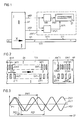
- a first photoelectric length measuring device is shown schematically in a longitudinal view, which consists of a first graduation carrier TT1 and consists of a first scanning device A1, which are each connected in a manner not shown to objects whose mutual relative position is to be measured; these two objects can be formed for example by a carriage and the bed of a processing machine, not shown.
- an incremental measuring graduation MT1 in the form of a line grating is applied to a surface O1 of the graduation carrier TT1, the graduation lines SM1 of which run perpendicular to the measuring graduation X and which has a grating constant GM1.
- the incremental measuring graduation MT1 is assigned an incremental additional graduation ZT1 on the surface O1 of the graduation carrier TT1, likewise in the form of a line grating, the graduation lines SZ1 of which likewise run perpendicular to the measuring direction X and which has a grating constant GZ1.
- the lattice constant GZ1 of the additional graduation ZT1 is greater than the lattice constant GM1 of the measuring graduation MT1.
- the graduation carrier TT1 is assigned a scanning plate AP in the scanning device A1, which has a measuring scanning graduation MAT1 and an additional scanning graduation ZAT1.
- the measuring scanning graduation MAT1 is identical with the measuring graduation MT1 and has the same grating constant GM1 of the measuring graduation MT1; the graduation lines SMA1 of the measuring scanning division MAT1 run perpendicular to the measuring direction X.
- the additional scanning division ZAT1 is identical to the additional division ZT1 and has the same grating constant GZ1 the additional division ZT1 on; the division lines SZA1 of the additional scanning division ZAT1 run perpendicular to the measuring direction X.
- an illumination unit with a condenser and two photo elements are arranged in the scanning device A1, each of which is assigned to the measuring scanning division MAT1 and the additional scanning division ZAT1.
- the luminous flux emanating from the lighting unit is directed in parallel by the condenser and falls on the one hand after the gradual assertion of the measuring graduation MT1 and the measuring scanning graduation MAT1 on the assigned photo element for generating a measuring scanning signal MS1 and on the other hand after the gradual assertion of the additional graduation ZT1 and the additional scanning graduation ZAT1 on the assigned photo element for generating an additional scanning signal ZS1.
- the measuring scanning signal MS1 and the additional scanning signal ZS1 Due to the modulation of the luminous flux by the divisions MT1, MAT1, ZT1, ZAT1 during the measuring movement of the scanning device A1 relative to the graduation carrier TT1, the measuring scanning signal MS1 and the additional scanning signal ZS1 have a sinusoidal course and are shown enlarged in FIG. 3 as a function of the measuring section s1.
- the measurement scanning signal MS1 is converted once in a measurement trigger TR1 into a square-wave signal RS1 and a counter Z1 for counting the graduation increments of the measuring graduation MT1 when scanned by the scanning device A1.
- the counting results of the counter Z1 form the measured values for the relative position of the two objects which can be moved relative to one another and can be displayed in digital form.
- the measurement scanning signal MS1 together with the additional scanning signal ZS1 is fed to a phase comparator PV1, which determines their mutual phase difference PD1 as a function of the measuring section s1.
- These points P1 can be defined as "reference marks” so that the phase comparator PV1 generates a reference pulse RP1 at each of these points P1, which can be used, for example, to reset the counter Z1 or to check the correctness of the measured values along the measuring path s1.
- the graduation marks SM1 of the measuring graduation MT1 and / or the graduation marks SZ1 of the additional graduation ZT1 can also run obliquely to the measuring direction X.
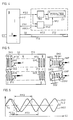
- FIG. 4 schematically shows a second photoelectric length measuring device in a longitudinal view, which consists of a second graduation carrier TT2 and a second scanning device A2, which are each connected in a manner not shown to objects whose mutual relative position is to be measured; these two objects can be formed for example by a carriage and the bed of a processing machine, not shown.
- the incremental measuring graduation MT2 is assigned an incremental graduation ZT2 on the surface O2 of the inclination carrier TT2, likewise in the form of a grating, the graduation marks SZ2 of which form an angle ⁇ ⁇ ⁇ with the measuring direction X and which has a grating constant GZ2.
- the two lattice constants GM2, GZ2 are of the same size and are each defined as the distance between adjacent division lines SM2, SZ2.
- the incremental additional graduation ZT2 of the graduation carrier TT2 is assigned an additional scanning plate ZAP with an additional scanning graduation ZAT2 in the scanning device A2, which has the same grating constant GZ2 of the additional graduation ZT2 and whose graduation marks SZA2 with the measuring direction X enclose the same angle ⁇ ⁇ ⁇ .
- the additional scanning plate ZAP with the additional scanning division ZAT2 and the measuring scanning plate MAP with the measuring scanning division MAT2 are identical; the additional scanning plate ZAP is only rotated relative to the measuring scanning plate MAP by an angle ⁇ - ⁇ in the drawing plane of FIG. 5.
- an illuminating unit with a condenser and two photo elements are arranged in the scanning device A2, each of which is assigned to the measuring scanning division MAT2 and the additional scanning division ZAT2.
- the luminous flux emanating from the lighting unit is directed in parallel by the condenser and falls on the one hand after the gradual assertion of the measuring graduation MT2 and the measuring scanning graduation MAT2 on the assigned photo element for generating a measuring scanning signal MS2 and on the other hand after the gradual assertion of the additional graduation ZT2 and the additional scanning graduation ZAT2 on the assigned photo element for generating an additional scanning signal ZS2.
- the measurement scanning signal MS2 and the additional scanning signal ZS2 have a sinusoidal course due to the modulation of the luminous flux by the divisions MT2, MAT2, ZT2, ZAT2 during the measuring movement of the scanning device A2 relative to the division carrier TT2 and are shown enlarged in FIG. 6 as a function of the measuring section s2.
- the measurement scanning signal MS2 together with the additional scanning signal ZS2 is fed to a phase comparator PV2, which determines their mutual phase difference PD2 as a function of the measuring section s2.
- a phase comparator PV2 determines their mutual phase difference PD2 as a function of the measuring section s2.
- These points P2 can be defined as "reference marks” so that the phase comparator PV2 generates a reference pulse RP2 at each of these points P2, which can be used, for example, to reset the counter Z2 or to check the correctness of the measured values along the measuring path s2.
- the scanning device A2 can also be formed from two identical scanning units with their own lighting units.
- the divisions can optionally be designed as an amplitude grating and / or as a phase grating.
- the invention can be used successfully both in incremental and in absolute position measuring systems which operate on the photoelectric, magnetic, capacitive or inductive measuring principle.
- the finest division of the code division is assigned the at least one additional division.
- the reference pulses obtained can be used to check the correctness of the absolute measured values.
Landscapes
- Physics & Mathematics (AREA)
- General Physics & Mathematics (AREA)
- Optical Transform (AREA)
- Transmission And Conversion Of Sensor Element Output (AREA)
- Vehicle Body Suspensions (AREA)
- Body Structure For Vehicles (AREA)
- Eye Examination Apparatus (AREA)
- Length Measuring Devices By Optical Means (AREA)
Claims (5)
- Dispositif de mesure de position pour mesurer la position relative de deux objets, dans lequel un support de graduation porte une graduation de mesure et au moins une graduation auxiliaire qui sont lues par un dispositif de lecture pour produire des signaux de lecture périodiques de durée de période variable, lesquels signaux sont envoyés à un dispositif d'exploitation pour former des impulsions de référence, caractérisé par le fait que les signaux de lecture (MS, ZS) périodiques sont comparés au niveau de leur déphasage (PD) mutuel par un comparateur de phase (PV) à l'intérieur du dispositif d'exploitation (AW) et par le fait qu'en présence d'un déphasage (PD) prédéterminé entre les signaux de lecture (MS, ZS), le comparateur de phase (PV) délivre une impulsion de référence (RP).
- Dispositif de mesure de position selon la revendication 1, caractérisé par le fait que la graduation de mesure (MT1) et la graduation auxiliaire (ZT1) présentent des constantes de réseau (GM1, GZ1) différentes et par le fait que les repères graduation (SM1) de la graduation de mesure (MT1) et les repères de graduation (SZ1) de la graduation auxiliaire (ZT1) sont perpendiculaires à la direction de mesure X.
- Dispositif de mesure de position selon la revendication 2, caractérisé par le fait que les repères de graduation de la graduation de mesure et/ou les repères de graduation de la graduation auxiliaire sont sont inclinés par rapport à la direction de mesure.
- Dispositif de mesure de position selon la revendication 1, caractérisé par le fait que la graduation de mesure (MT2) et la graduation auxiliaire (ZT2) présentent des constantes de réseau (GM2, GZ2) identiques et par le fait que les repères graduation (SM2) de la graduation de mesure (MT2) forment un angle α avec la direction de mesure X et les repères de graduation (SZ2) de la graduation auxiliaire (ZT2) forment un angle β ≠ α avec la direction de mesure X.
- Dispositif de mesure de position selon les revendications 1 et 4, caractérisé par le fait que le dispositif de lecture (A2) comporte une plaque de lecture de mesure (MAP), avec une graduation de lecture de mesure (MAT2) et une plaque de lecture auxiliaire (ZAP) identique avec une graduation de lecture auxiliaire (ZAT2) identique, par le fait que la graduation de lecture de mesure (MAT2) et la graduation de lecture auxiliaire (ZAT2) ont les mêmes constantes de réseau (GM2, GZ2) que la graduation de mesure (MT2) et la graduation auxiliaire (ZT2) et par le fait que les repères de graduation (SMA2) de la graduation de lecture de mesure (MAT2) forment l'angle α et les repères de graduation (SZA2) de la graduation de lecture auxiliaire (ZAT2) l'angle β avec la direction de mesure X.
Priority Applications (1)
| Application Number | Priority Date | Filing Date | Title |
|---|---|---|---|
| AT89100358T ATE93619T1 (de) | 1988-01-22 | 1989-01-11 | Positionsmesseinrichtung. |
Applications Claiming Priority (2)
| Application Number | Priority Date | Filing Date | Title |
|---|---|---|---|
| DE3801763 | 1988-01-22 | ||
| DE3801763A DE3801763C1 (fr) | 1988-01-22 | 1988-01-22 |
Publications (3)
| Publication Number | Publication Date |
|---|---|
| EP0325149A2 EP0325149A2 (fr) | 1989-07-26 |
| EP0325149A3 EP0325149A3 (fr) | 1991-05-29 |
| EP0325149B1 true EP0325149B1 (fr) | 1993-08-25 |
Family
ID=6345759
Family Applications (1)
| Application Number | Title | Priority Date | Filing Date |
|---|---|---|---|
| EP89100358A Expired - Lifetime EP0325149B1 (fr) | 1988-01-22 | 1989-01-11 | Dispositif de mesure de la position |
Country Status (3)
| Country | Link |
|---|---|
| EP (1) | EP0325149B1 (fr) |
| AT (1) | ATE93619T1 (fr) |
| DE (2) | DE3801763C1 (fr) |
Families Citing this family (5)
| Publication number | Priority date | Publication date | Assignee | Title |
|---|---|---|---|---|
| EP0502534B1 (fr) * | 1991-03-06 | 1997-12-17 | Hitachi, Ltd. | Codeur |
| DE9116791U1 (de) * | 1991-08-03 | 1993-11-04 | Heidenhain Gmbh Dr Johannes | Längen- oder Winkelmeßeinrichtung |
| DE59201199D1 (de) * | 1992-02-14 | 1995-02-23 | Heidenhain Gmbh Dr Johannes | Wegmesseinrichtung. |
| WO1999027324A2 (fr) * | 1997-11-25 | 1999-06-03 | Microe, Inc. | Codeur absolu multipistes |
| DE10013725A1 (de) * | 2000-03-21 | 2001-10-11 | Hannover Laser Zentrum | Meßvorrichtung sowie Verfahren zur Messung eines Weges bei einer Relativbewegung zwischen der Meßvorrichtung und einem Maßstab, der eine Meßspur mit einem Beugungsgitter aufweist, sowie miniaturisierter optischer Abtastkopf |
Family Cites Families (6)
| Publication number | Priority date | Publication date | Assignee | Title |
|---|---|---|---|---|
| DE1258120B (de) * | 1961-06-29 | 1968-01-04 | Kern & Co Ag | Verfahren zum Messen von Laengen mittels einer aus Strichfolgen bestehenden Teilung und einer Ablesevorrichtung und Vorrichtung zur Durchfuehrung dieses Verfahrens |
| DE1282988B (de) * | 1965-05-28 | 1968-11-14 | Zeiss Carl Fa | Einrichtung zum Messen von Lageaenderungen zweier zueinander beweglicher Teile unterVerwendung einer inkohaerenten Strahlung |
| US4340305A (en) * | 1977-05-03 | 1982-07-20 | Massachusetts Institute Of Technology | Plate aligning |
| DE3102125A1 (de) * | 1981-01-23 | 1982-08-05 | Dr. Johannes Heidenhain Gmbh, 8225 Traunreut | Inkrementale laengen- oder winkelmesseinrichtung |
| DE3308813C2 (de) * | 1983-03-12 | 1985-02-07 | Dr. Johannes Heidenhain Gmbh, 8225 Traunreut | Meßeinrichtung |
| DE3417176C2 (de) * | 1984-05-09 | 1986-07-31 | Dr. Johannes Heidenhain Gmbh, 8225 Traunreut | Photoelektrische Meßeinrichtung |
-
1988
- 1988-01-22 DE DE3801763A patent/DE3801763C1/de not_active Expired
-
1989
- 1989-01-11 DE DE89100358T patent/DE58905343D1/de not_active Expired - Fee Related
- 1989-01-11 AT AT89100358T patent/ATE93619T1/de not_active IP Right Cessation
- 1989-01-11 EP EP89100358A patent/EP0325149B1/fr not_active Expired - Lifetime
Also Published As
| Publication number | Publication date |
|---|---|
| EP0325149A3 (fr) | 1991-05-29 |
| DE3801763C1 (fr) | 1989-06-08 |
| DE58905343D1 (de) | 1993-09-30 |
| ATE93619T1 (de) | 1993-09-15 |
| EP0325149A2 (fr) | 1989-07-26 |
Similar Documents
| Publication | Publication Date | Title |
|---|---|---|
| EP0246404B1 (fr) | Méthode de mesure | |
| DE3239108C2 (fr) | ||
| EP0268558B1 (fr) | Appareil pour la mesure de longueurs ou d'angles | |
| EP0696722B1 (fr) | Dispositif de mesure de positions | |
| EP1400778A2 (fr) | Dispositif de mesure de position | |
| EP0172323A1 (fr) | Appareil de mesure | |
| DE3308814A1 (de) | Messeinrichtung | |
| EP0137099A1 (fr) | Appareil de mesure | |
| EP1995566B1 (fr) | Echelle pour un dispositif de mesure de position et dispositif de mesure de position | |
| EP0121658B1 (fr) | Dispositif de mesure | |
| EP0530176A1 (fr) | Dispositif de mesure linéaire ou angulaire | |
| DE3640413C2 (de) | Meßanordnung | |
| CH672679A5 (fr) | ||
| EP0325149B1 (fr) | Dispositif de mesure de la position | |
| DE10043635A1 (de) | Vorrichtung zur Positionsbestimmung und Ermittlung von Führungsfehlern | |
| DE3636744C1 (de) | Lichtelektrische Laengen- oder Winkelmesseinrichtung | |
| DE4125865C2 (de) | Längen- oder Winkelmeßeinrichtung | |
| EP0421024B1 (fr) | Dispositif photoélectrique de mesure de position | |
| EP0585622A2 (fr) | Procédé pour appareil de mesure de longueur ou d'angle | |
| DE3611204C2 (fr) | ||
| EP0526730A1 (fr) | Capteur de position linéaire ou angulaire | |
| EP0479759B1 (fr) | Procédé et dispositif pour la mesure de longueurs ou d'angles | |
| DE3509682C2 (fr) | ||
| DE2333698B1 (de) | Digitaler Positionsgeber | |
| DE3417015C2 (de) | Interpolationsverfahren |
Legal Events
| Date | Code | Title | Description |
|---|---|---|---|
| PUAI | Public reference made under article 153(3) epc to a published international application that has entered the european phase |
Free format text: ORIGINAL CODE: 0009012 |
|
| 17P | Request for examination filed |
Effective date: 19890124 |
|
| AK | Designated contracting states |
Kind code of ref document: A2 Designated state(s): AT CH DE ES FR GB IT LI NL SE |
|
| PUAL | Search report despatched |
Free format text: ORIGINAL CODE: 0009013 |
|
| AK | Designated contracting states |
Kind code of ref document: A3 Designated state(s): AT CH DE ES FR GB IT LI NL SE |
|
| 17Q | First examination report despatched |
Effective date: 19920810 |
|
| RBV | Designated contracting states (corrected) |
Designated state(s): AT CH DE FR GB IT LI |
|
| ITF | It: translation for a ep patent filed |
Owner name: DE DOMINICIS & MAYER S.R.L. |
|
| GRAA | (expected) grant |
Free format text: ORIGINAL CODE: 0009210 |
|
| AK | Designated contracting states |
Kind code of ref document: B1 Designated state(s): AT CH DE FR GB IT LI |
|
| REF | Corresponds to: |
Ref document number: 93619 Country of ref document: AT Date of ref document: 19930915 Kind code of ref document: T |
|
| GBT | Gb: translation of ep patent filed (gb section 77(6)(a)/1977) |
Effective date: 19930823 |
|
| REF | Corresponds to: |
Ref document number: 58905343 Country of ref document: DE Date of ref document: 19930930 |
|
| ET | Fr: translation filed | ||
| PG25 | Lapsed in a contracting state [announced via postgrant information from national office to epo] |
Ref country code: AT Effective date: 19940111 |
|
| PG25 | Lapsed in a contracting state [announced via postgrant information from national office to epo] |
Ref country code: LI Effective date: 19940131 Ref country code: CH Effective date: 19940131 |
|
| PLBE | No opposition filed within time limit |
Free format text: ORIGINAL CODE: 0009261 |
|
| STAA | Information on the status of an ep patent application or granted ep patent |
Free format text: STATUS: NO OPPOSITION FILED WITHIN TIME LIMIT |
|
| 26N | No opposition filed | ||
| REG | Reference to a national code |
Ref country code: CH Ref legal event code: PL |
|
| PGFP | Annual fee paid to national office [announced via postgrant information from national office to epo] |
Ref country code: FR Payment date: 20011226 Year of fee payment: 14 |
|
| REG | Reference to a national code |
Ref country code: GB Ref legal event code: IF02 |
|
| PGFP | Annual fee paid to national office [announced via postgrant information from national office to epo] |
Ref country code: GB Payment date: 20021227 Year of fee payment: 15 |
|
| PG25 | Lapsed in a contracting state [announced via postgrant information from national office to epo] |
Ref country code: FR Free format text: LAPSE BECAUSE OF NON-PAYMENT OF DUE FEES Effective date: 20030930 |
|
| REG | Reference to a national code |
Ref country code: FR Ref legal event code: ST |
|
| PG25 | Lapsed in a contracting state [announced via postgrant information from national office to epo] |
Ref country code: GB Free format text: LAPSE BECAUSE OF NON-PAYMENT OF DUE FEES Effective date: 20040111 |
|
| GBPC | Gb: european patent ceased through non-payment of renewal fee |
Effective date: 20040111 |
|
| PG25 | Lapsed in a contracting state [announced via postgrant information from national office to epo] |
Ref country code: IT Free format text: LAPSE BECAUSE OF NON-PAYMENT OF DUE FEES;WARNING: LAPSES OF ITALIAN PATENTS WITH EFFECTIVE DATE BEFORE 2007 MAY HAVE OCCURRED AT ANY TIME BEFORE 2007. THE CORRECT EFFECTIVE DATE MAY BE DIFFERENT FROM THE ONE RECORDED. Effective date: 20050111 |
|
| PGFP | Annual fee paid to national office [announced via postgrant information from national office to epo] |
Ref country code: DE Payment date: 20070110 Year of fee payment: 19 |
|
| PG25 | Lapsed in a contracting state [announced via postgrant information from national office to epo] |
Ref country code: DE Free format text: LAPSE BECAUSE OF NON-PAYMENT OF DUE FEES Effective date: 20080801 |