EP0324932A1 - Apparatus for making a post-foaming gel - Google Patents
Apparatus for making a post-foaming gel Download PDFInfo
- Publication number
- EP0324932A1 EP0324932A1 EP88120038A EP88120038A EP0324932A1 EP 0324932 A1 EP0324932 A1 EP 0324932A1 EP 88120038 A EP88120038 A EP 88120038A EP 88120038 A EP88120038 A EP 88120038A EP 0324932 A1 EP0324932 A1 EP 0324932A1
- Authority
- EP
- European Patent Office
- Prior art keywords
- gel
- emulsion
- foaming agent
- pumping
- conduit
- Prior art date
- Legal status (The legal status is an assumption and is not a legal conclusion. Google has not performed a legal analysis and makes no representation as to the accuracy of the status listed.)
- Granted
Links
Images


Classifications
-
- B—PERFORMING OPERATIONS; TRANSPORTING
- B01—PHYSICAL OR CHEMICAL PROCESSES OR APPARATUS IN GENERAL
- B01F—MIXING, e.g. DISSOLVING, EMULSIFYING OR DISPERSING
- B01F23/00—Mixing according to the phases to be mixed, e.g. dispersing or emulsifying
- B01F23/40—Mixing liquids with liquids; Emulsifying
- B01F23/49—Mixing systems, i.e. flow charts or diagrams
Definitions
- the present invention relates to an apparatus and method for making a post-foaming gel.
- any post foaming gel of cosmetically acceptable stiffness will tend to foam spontaneously when exposed to atmospheric pressure if it contains bubbles of air or hydrocarbon. These act as nuclei for foaming, by expanding and shearing the gel in their immediate vicinity.
- pentane/butane mixtures cannot be incorporated into gel base in a conventional, partly-filled pressure vessel, even when the headspace is pressurized with air or nitrogen. Inevitably some of the water-soluble gas will be entrained in the gel. The resulting spontaneous foaming makes filling into cans very difficult and messy. Even then the product will not settle down on storage to give a satisfactory result.
- bubbly gels are not suitable for packing into cans because the external propellant used with the cans gives insufficient pressure to collapse the bubbles on storage. This is largely due to the fact that these gels have a yield value such that they resist the applied pressure (or fail to transmit the full effect to the bubbles).
- a post-foaming gel is disclosed in U.S. patent 3,541,581.
- a continuous method and apparatus to make a post-foaming gel is disclosed in U.S. 4,405,489.
- the filling of an aerosol can containing an interior plastic bag which holds the product to be dispensed is disclosed in U.S. 4,589,452.
- the U. S. Patent 4,405,489 discloses metering pumps 24 and 25 having a single device mechanism 26 on their own drive mechanism.
- a principal feature of the present invention is the provision of an apparatus for making a post-foaming gel.
- the apparatus of the present invention comprises, means for pumping a gel base, means for introducing a foaming agent to the gel base, and means for forming the post-foaming gel or emulsion from the introducing means.
- a feature of the present invention is the provision of means for measuring the flow rate of the pumped gel base.
- Another feature of the invention is the provision of means responsive to the measuring means for pumping the foaming agent at a flow rate in a predetermined ratio to the flow rate of the gel base.
- a feature of the invention is that the desired ratio of the base and foaming agent is automatically determined.
- Another feature of the invention is that the desired ratio of base and foaming agent may be varied.
- a further feature of the invention is that the base and gel are controlled in a simplified manner.
- Another feature of the invention is that the apparatus is flame proof.
- a feature of the invention is that the apparatus is of significant construction at reduced cost.
- Yet another feature of the invention is that the rate of the base pumping means may be controlled.
- Still another feature of the invention is the provision of means for smoothing out the flow pulsation from the base pumping means.
- a feature of the invention is that the foaming agent pumping means is variable.
- Another feature of the invention is the provision of means for measuring the flow rate of the foaming agent passing through the foaming agent pumping means.
- a feature of the invention is that the flow rates of the base and foaming agent can be compared.
- Another feature of the invention is the provision of means for bleeding air and vapor from the foaming agent.
- Yet another feature of the invention is the provision of means for storing the foamed gel or emulsion under pressure.
- the gel or emulsion may be selectively passed to a plurality of storage cylinders.
- a feature of the invention is that maximum and minimum filled conditions of the container may be determined.
- Another feature of the invention is that the apparatus provides a continuous gel manufacture with simultaneous can filling capacity.
- the pumping means may be interrupted in the event of the maximum and minimum filled conditions of the container.
- FIG. 1 there is shown an apparatus generally designated 10 for making a post-foaming gel from a gel base and foaming agent.
- the apparatus 10 has a storage container 12 for retaining the gel base, with the container 12 being connected to a pump 14 by a conduit 16.
- the pump 14 is capable of pumping 1,000 liters/ hour, and the rate of the pump 14 may be manually varied by a control device 18 on the pump 14.
- the pump 14 is connected by a conduit 20 to a non-return valve 22 to prevent passage of the foaming agent to the pump 14 and render the apparatus flame-proof.
- the valve 22 is connected by a conduit 24 to a pressure relief valve 26 to prevent excessive pressure in the apparatus 10.
- the gel base is passed through a conduit 28 to a pulsation dampener 30 to smooth out flow pulsation of the pumped gel base.
- the gel base passes from the dampener 30 through a conduit 32 to a flow meter 34 which determines the flow rate of the gel base between minimum and maximum limits, such as a range of 0-1000 liters per hour.
- the flow meter 34 generates an electrical signal indicative of the base flow rate.
- the signal is fed to a current-to-pressure convertor which transforms the electrical signal into a pneumatic signal for a purpose which will be described below.
- the gel base then passes through a conduit 36 to a location 38 in the apparatus 10.
- a source of the foaming agent is retained in a container 40, and the foaming agent passes from the container 40 through a conduit 42 to a pump 44 which maintains the foaming agent in liquid form.
- the foaming agent passes from pump 44 through a conduit 46 to a valve 48.
- the apparatus 10 has a pneumatic stroke positioner 51 based on a highly responsive, fast acting wedge/cylinder mechanism which adjusts the setting in proportion to 0.2 to 1 bar (3 to 15 lb/in.2) air signal 49. Failure of the air signal or absence of air pressure, returns the stroke setting to zero.
- the foaming agent then passes through a conduit 50 to the pump-head 53 of a metering pump 52.
- the pump 52 has a first one-way ball valve 54 which moves between a first position away from a seat 56 to permit passage of the foaming agent through the valve 54 into a chamber 58, and a second position against the seat 56 to prevent passage of the foaming agent from the chamber 58 to the conduit 50.
- the pump 52 has a second one-way ball valve 60 which moves from a first position away from a seat 62 to permit passage of the foaming agent from the chamber 58 to a conduit 64, and a second position against the seat 62 to prevent passage of the foaming agent or gel base from the conduit 64 to the chamber 58.
- the pump 52 has an elongated cylinder 66 which slidibly receives a piston 68 connected to a shaft 70, and the piston 68 is reciprocated in the cylinder 66 while cooperating with the first and second valves 54 and 60 in order to pump the foaming agent into and out of the chamber 58.
- the rate of reciprocation of the piston 68 is controlled by the pneumatic signal from the flow meter 34 in order to control the pumping rate of the foaming agent at a predetermined ratio relative to the flow rate of the gel base.
- the pump 52 is calibrated to obtain the desired ratio of gel base and foaming agent, and the ratio may be changed by suitable calibrations if desired.
- the pumped foaming agent passes through the conduit 64 to a pressure relief valve 72 to prevent excessive pressure of the foaming agent in the apparatus 10, and the foaming agent then passes through a non return valve 74 which prevents backward movement of the foaming agent in the apparatus 10.
- the foaming agent passes through a flow meter 75 which determines the flow rate of the foaming agent such that the flow ratio of the gel base and foaming agent can be compared.
- the foaming agent then passes through a conduit 76 to a bleed off valve 78 to bleed off air or vapor while a manual valve 80 is closed to verify that the foaming agent is in liquid form. Once air or vapor is bled from the foaming agent, the valve 80 is opened to permit passage of the pumped foaming agent to the location 38 to permit contact with the pumped gel base.
- Both the gel base and foaming agent are pumped from location 38 through a conduit 82 to a mixer 84 which may be a static or dynamic mixer or both.
- the mixer 84 forms the post-foaming gel or an emulsion from the gel base and foaming agent depending upon the conditions of the apparatus 10, such as temperature.
- the gel or emulsion then passes through a conduit 86 to a valve 88 for a purpose which will be described below.
- the apparatus 10 has a storage cylinder 90 having a chamber 92 and a piston 94 slidibly received in the chamber 92, with the piston 94 having a shaft 96 which extends out of the cylinder 90.
- the piston 94 separates the chamber 94 into a first compartment 98 to receive the gel or emulsion and a second compartment 100 to receive a compressed gas through a conduit 102 from a source of pressurized gas, such as 50-100 pounds/square inch, which may be varied to control pressure on the piston 94.
- the gel or emulsion is pumped into the first compartment 98 against the pressure on the piston 94 which is controlled to obtain a pressure in the preferred range of 60-100 pounds/square inch in order to maintain the foaming agent in a liquid condition without vaporizing.
- valve 88 may be closed and the gel or emulsion is passed through a valve 104 to suitable containers.
- the gel it is passed into container 106 with an open top after which a valve is attached to the container 106 for dispensing the gel once the container 106 is prepared with a suitable propellant known to the art.
- the emulsion it is passed through the activated valves 108 of suitable containers 110 know to the art in order to obtain a secondary mixing by the valves 108 and form the emulsion into the post-foaming gel in the containers 110.
- the containers are prepared with a suitable propellant as known to the art in order to dispense the gel from the containers 110 when the valves 108 are activated.
- the apparatus has a pair of cylinders 90 and 112 of the type previously described.
- the gel or emulsion is passed from the mixer 84 through a conduit 114.
- the gel or emulsion passes from conduit 114 through a conduit 116 with a manual valve 118 associated with the conduit 116 connected to the container 90.
- the gel or emulsion also passes from conduit 114 through a conduit 120 with a manual valve 122 associated with the conduit 120 to the cylinder 112.
- the valves 118 and 122 may be controlled as desired to sequentially fill the cylinders 90 and 112, after which the gel or emulsion is emptied from the cylinders 90 and 112 in a manner as previously described.
- the conduit 120 may have a temperature probe 124 in order to measure the temperature of the gel or emulsion.
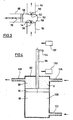
- FIG. 4 A preferred form of the cylinder 90 is shown in Fig. 4, in which like reference numerals designate like parts.
- the gel or emulsion G passes through a conduit 126 into the first compartment 98 of the cylinder 90, in a manner as previously described, and the gel or emulsion passes from the cylinder 90 out of a conduit 128 to fill the containers for dispensing of the product.
- the apparatus 10 has a high level lower switch 130 and a low level upper switch 132 which may be activated by the position of a pin 134 on the piston shaft 96.
- the switch 130 When the cylinder 90 is sufficiently full of the gel or emulsion G, the switch 130 is activated, and the apparatus, including the pumps, is turned off to prevent the build up of pressure in the apparatus when a maximum quantity of the product is in the cylinder 90.
- the piston 94 of cylinder 90 may be used as a buffer to pass the product from the conduit 126 through the cylinder 90 into the conduit 128 until activation of the switch 132 is discontinued, and passage of the product through the cylinder is thereafter maintained unless the switch 132 is contacted again in which event the filling apparatus downstream from conduit 128 is switched off to prevent 'starvation' of gel or emulsion to the filling apparatus.
- the gel base is made in the following manner according to the formulation set forth below:
- the gel base has the following formulation: BASE % Palmitic Acid 8.0 - 10.0 Stearic Acid 1.0 - 3.0 Triethanolamine 5.5 - 7.5 Sorbitol - 70% solution up to 3.0 Hydroxyethyl cellulose 0.1 - 0.4 Hydroxypropyl cellulose 0.05 - 0.15 Glyceryl Monostearate 0.4 - 0.6 Perfume q.s. Coloring Material q.s. Water to 100%
- the finished product has the following formulation: FINISHED PRODUCT Base as above 97.0 - 98.0 Iso-Pentane 1.5 - 1.8 Iso-Butane 0.5 - 1.2
- the apparatus 10 provides continuous gel manufacture with simultaneous can filling capacity.
- the present invention is thus an improvement over batch process gel manufacture due to reduced production time, and the product can be filled immediately (within 1-2 minutes) of being formed.
Abstract
Description
- The present invention relates to an apparatus and method for making a post-foaming gel.
- Before the present invention, attempts have been made to add foaming agents, such as pentane/butane mixtures to gel bases in conventional partly filled pressure vessels to make a post-foaming gel. However, any post foaming gel of cosmetically acceptable stiffness will tend to foam spontaneously when exposed to atmospheric pressure if it contains bubbles of air or hydrocarbon. These act as nuclei for foaming, by expanding and shearing the gel in their immediate vicinity. This means that pentane/butane mixtures cannot be incorporated into gel base in a conventional, partly-filled pressure vessel, even when the headspace is pressurized with air or nitrogen. Inevitably some of the water-soluble gas will be entrained in the gel. The resulting spontaneous foaming makes filling into cans very difficult and messy. Even then the product will not settle down on storage to give a satisfactory result.
- Taking a potentially 'easy' situation, such as adding only isopentane(B.Pt. 29°C) or n-pentane (B.Pt. 37°C), there are still problems. Assuming a good gel is produced by cold mixing, you will find that at temperatures around 20°C the mixing does vaporise significant amounts of foaming agent and the resulting gel is foamy.
- These bubbly gels are not suitable for packing into cans because the external propellant used with the cans gives insufficient pressure to collapse the bubbles on storage. This is largely due to the fact that these gels have a yield value such that they resist the applied pressure (or fail to transmit the full effect to the bubbles).
- A post-foaming gel is disclosed in U.S. patent 3,541,581. A continuous method and apparatus to make a post-foaming gel is disclosed in U.S. 4,405,489. The filling of an aerosol can containing an interior plastic bag which holds the product to be dispensed is disclosed in U.S. 4,589,452.
- The U. S. Patent 4,405,489 discloses
metering pumps 24 and 25 having a single device mechanism 26 on their own drive mechanism. - A principal feature of the present invention is the provision of an apparatus for making a post-foaming gel.
- The apparatus of the present invention comprises, means for pumping a gel base, means for introducing a foaming agent to the gel base, and means for forming the post-foaming gel or emulsion from the introducing means.
- A feature of the present invention is the provision of means for measuring the flow rate of the pumped gel base.
- Another feature of the invention is the provision of means responsive to the measuring means for pumping the foaming agent at a flow rate in a predetermined ratio to the flow rate of the gel base.
- A feature of the invention is that the desired ratio of the base and foaming agent is automatically determined.
- Another feature of the invention is that the desired ratio of base and foaming agent may be varied.
- A further feature of the invention is that the base and gel are controlled in a simplified manner.
- Another feature of the invention is that the apparatus is flame proof.
- A feature of the invention is that the apparatus is of significant construction at reduced cost.
- Yet another feature of the invention is that the rate of the base pumping means may be controlled.
- Still another feature of the invention is the provision of means for smoothing out the flow pulsation from the base pumping means.
- A feature of the invention is that the foaming agent pumping means is variable.
- Another feature of the invention is the provision of means for measuring the flow rate of the foaming agent passing through the foaming agent pumping means.
- Thus, a feature of the invention is that the flow rates of the base and foaming agent can be compared.
- Another feature of the invention is the provision of means for bleeding air and vapor from the foaming agent.
- Yet another feature of the invention is the provision of means for storing the foamed gel or emulsion under pressure.
- Another feature of the invention is that the gel or emulsion may be selectively passed to a plurality of storage cylinders.
- A feature of the invention is that maximum and minimum filled conditions of the container may be determined.
- Another feature of the invention is that the apparatus provides a continuous gel manufacture with simultaneous can filling capacity.
- Still another feature of the invention is that the pumping means may be interrupted in the event of the maximum and minimum filled conditions of the container.
- Further features will become more fully apparent in the following description of the embodiments of this invention and from the appended claims.
- In the drawings:
- Fig. 1 is a diagrammatic view of an apparatus for making a post-foaming gel of the present invention;
- Fig. 2 is a diagrammatic view of a pair of storage cylinders for the apparatus of Fig. 1;
- Fig. 3 is a sectional view of a metering pump for the apparatus of Fig. 1;
- Fig. 4 is a sectional view of a storage cylinder for the apparatus of Fig. 1; and
- Fig. 5 is a diagrammatic view of a pneumatic stroke positioner.
- Referring now to Fig. 1, there is shown an apparatus generally designated 10 for making a post-foaming gel from a gel base and foaming agent. The apparatus 10 has a
storage container 12 for retaining the gel base, with thecontainer 12 being connected to apump 14 by aconduit 16. Typically, thepump 14 is capable of pumping 1,000 liters/ hour, and the rate of thepump 14 may be manually varied by acontrol device 18 on thepump 14. - The
pump 14 is connected by aconduit 20 to a non-return valve 22 to prevent passage of the foaming agent to thepump 14 and render the apparatus flame-proof. The valve 22 is connected by aconduit 24 to a pressure relief valve 26 to prevent excessive pressure in the apparatus 10. The gel base is passed through aconduit 28 to apulsation dampener 30 to smooth out flow pulsation of the pumped gel base. The gel base passes from thedampener 30 through aconduit 32 to aflow meter 34 which determines the flow rate of the gel base between minimum and maximum limits, such as a range of 0-1000 liters per hour. Theflow meter 34 generates an electrical signal indicative of the base flow rate. The signal is fed to a current-to-pressure convertor which transforms the electrical signal into a pneumatic signal for a purpose which will be described below. The gel base then passes through aconduit 36 to alocation 38 in the apparatus 10. - A source of the foaming agent is retained in a
container 40, and the foaming agent passes from thecontainer 40 through aconduit 42 to apump 44 which maintains the foaming agent in liquid form. The foaming agent passes frompump 44 through aconduit 46 to avalve 48. - The apparatus 10 has a
pneumatic stroke positioner 51 based on a highly responsive, fast acting wedge/cylinder mechanism which adjusts the setting in proportion to 0.2 to 1 bar (3 to 15 lb/in.²)air signal 49. Failure of the air signal or absence of air pressure, returns the stroke setting to zero. - With reference to Figs. 1, 3, and 5, the foaming agent then passes through a
conduit 50 to the pump-head 53 of ametering pump 52. Thepump 52 has a first one-way ball valve 54 which moves between a first position away from aseat 56 to permit passage of the foaming agent through thevalve 54 into achamber 58, and a second position against theseat 56 to prevent passage of the foaming agent from thechamber 58 to theconduit 50. Thepump 52 has a second one-way ball valve 60 which moves from a first position away from aseat 62 to permit passage of the foaming agent from thechamber 58 to aconduit 64, and a second position against theseat 62 to prevent passage of the foaming agent or gel base from theconduit 64 to thechamber 58. Thepump 52 has anelongated cylinder 66 which slidibly receives apiston 68 connected to ashaft 70, and thepiston 68 is reciprocated in thecylinder 66 while cooperating with the first andsecond valves chamber 58. The rate of reciprocation of thepiston 68 is controlled by the pneumatic signal from theflow meter 34 in order to control the pumping rate of the foaming agent at a predetermined ratio relative to the flow rate of the gel base. Thepump 52 is calibrated to obtain the desired ratio of gel base and foaming agent, and the ratio may be changed by suitable calibrations if desired. - The pumped foaming agent passes through the
conduit 64 to a pressure relief valve 72 to prevent excessive pressure of the foaming agent in the apparatus 10, and the foaming agent then passes through a non return valve 74 which prevents backward movement of the foaming agent in the apparatus 10. The foaming agent passes through aflow meter 75 which determines the flow rate of the foaming agent such that the flow ratio of the gel base and foaming agent can be compared. The foaming agent then passes through a conduit 76 to a bleed off valve 78 to bleed off air or vapor while amanual valve 80 is closed to verify that the foaming agent is in liquid form. Once air or vapor is bled from the foaming agent, thevalve 80 is opened to permit passage of the pumped foaming agent to thelocation 38 to permit contact with the pumped gel base. - Both the gel base and foaming agent are pumped from
location 38 through aconduit 82 to a mixer 84 which may be a static or dynamic mixer or both. The mixer 84 forms the post-foaming gel or an emulsion from the gel base and foaming agent depending upon the conditions of the apparatus 10, such as temperature. The gel or emulsion then passes through aconduit 86 to avalve 88 for a purpose which will be described below. - The apparatus 10 has a
storage cylinder 90 having achamber 92 and apiston 94 slidibly received in thechamber 92, with thepiston 94 having ashaft 96 which extends out of thecylinder 90. Thepiston 94 separates thechamber 94 into afirst compartment 98 to receive the gel or emulsion and asecond compartment 100 to receive a compressed gas through aconduit 102 from a source of pressurized gas, such as 50-100 pounds/square inch, which may be varied to control pressure on thepiston 94. The gel or emulsion is pumped into thefirst compartment 98 against the pressure on thepiston 94 which is controlled to obtain a pressure in the preferred range of 60-100 pounds/square inch in order to maintain the foaming agent in a liquid condition without vaporizing. - Once the
cylinder 90 is full, thevalve 88 may be closed and the gel or emulsion is passed through avalve 104 to suitable containers. In the event of the gel, it is passed intocontainer 106 with an open top after which a valve is attached to thecontainer 106 for dispensing the gel once thecontainer 106 is prepared with a suitable propellant known to the art. In the event of the emulsion, it is passed through the activatedvalves 108 ofsuitable containers 110 know to the art in order to obtain a secondary mixing by thevalves 108 and form the emulsion into the post-foaming gel in thecontainers 110. The containers are prepared with a suitable propellant as known to the art in order to dispense the gel from thecontainers 110 when thevalves 108 are activated. - In a preferred form, with reference to Fig. 2, the apparatus has a pair of
cylinders conduit 114. The gel or emulsion passes fromconduit 114 through aconduit 116 with amanual valve 118 associated with theconduit 116 connected to thecontainer 90. The gel or emulsion also passes fromconduit 114 through aconduit 120 with amanual valve 122 associated with theconduit 120 to thecylinder 112. Thevalves cylinders cylinders conduit 120 may have atemperature probe 124 in order to measure the temperature of the gel or emulsion. - A preferred form of the
cylinder 90 is shown in Fig. 4, in which like reference numerals designate like parts. In this embodiment, the gel or emulsion G passes through aconduit 126 into thefirst compartment 98 of thecylinder 90, in a manner as previously described, and the gel or emulsion passes from thecylinder 90 out of aconduit 128 to fill the containers for dispensing of the product. As shown, the apparatus 10 has a high levellower switch 130 and a low levelupper switch 132 which may be activated by the position of apin 134 on thepiston shaft 96. When thecylinder 90 is sufficiently full of the gel or emulsion G, theswitch 130 is activated, and the apparatus, including the pumps, is turned off to prevent the build up of pressure in the apparatus when a maximum quantity of the product is in thecylinder 90. Normally, thepiston 94 ofcylinder 90 may be used as a buffer to pass the product from theconduit 126 through thecylinder 90 into theconduit 128 until activation of theswitch 132 is discontinued, and passage of the product through the cylinder is thereafter maintained unless theswitch 132 is contacted again in which event the filling apparatus downstream fromconduit 128 is switched off to prevent 'starvation' of gel or emulsion to the filling apparatus. - The gel base is made in the following manner according to the formulation set forth below:
- (1) Add approximately 20% of the water to a closed mixing vessel.
- (2) Add fatty acid to the mixing vessel and then the GMS/color then heat to 80-85°C until all powders are molten.
- (3) Add the triethanolamine to the vessel with agitation to form a soap. Cool to 60°C. Add the Hydroxyethyl cellulose.
- (4) Cool to 40°C and add the Hydroxypropyl cellulose.
- (5) Add the sorbitol solution, with agitation, to the aqueous soap.
- (6) Cool the mixture to 30°C, add the perfume with agitation.
- The gel base has the following formulation:
BASE % Palmitic Acid 8.0 - 10.0 Stearic Acid 1.0 - 3.0 Triethanolamine 5.5 - 7.5 Sorbitol - 70% solution up to 3.0 Hydroxyethyl cellulose 0.1 - 0.4 Hydroxypropyl cellulose 0.05 - 0.15 Glyceryl Monostearate 0.4 - 0.6 Perfume q.s. Coloring Material q.s. Water to 100% - The finished product has the following formulation:
FINISHED PRODUCT Base as above 97.0 - 98.0 Iso-Pentane 1.5 - 1.8 Iso-Butane 0.5 - 1.2 - In accordance with the present invention, the apparatus 10 provides continuous gel manufacture with simultaneous can filling capacity. The present invention is thus an improvement over batch process gel manufacture due to reduced production time, and the product can be filled immediately (within 1-2 minutes) of being formed.
- The foregoing detailed description is given for clearness of understanding only, and no unnecessary limitations should be understood therefrom, as modifications will be obvious to those skilled in the art.
Claims (23)
means for pumping a gel base;
means for measuring the flow rate of the pumped gel base;
means responsive to the measuring means for pumping a foaming agent at a flow rate in a predetermined ratio to the flow rate of the gel base;
means for introducing the foaming agent to the gel base; and
means for forming the post-foaming gel or emulsion from the introducing means.
means for making the gel or emulsion;
a first storage container to receive the gel or emulsion;
a second storage container to receive the gel or emulsion; and
means for selectively passing the gel or emulsion to the first and second container.
means for making and pumping the gel or emulsion;
a storage cylinder having a chamber;
a piston slidibly received in the cylinder and separating the chamber into a first compartment to receive the gel or emulsion, and a second compartment;
means for driving the piston toward the gel in the first compartment;
means for introducing the gel or emulsion into the first compartment, and
means for removing the gel or emulsion from the first compartment.
means for continuously making the gel or emulsion; and
means for filling a container with the gel or emulsion substantially simultaneously while making the gel or emulsion by the making means.
Priority Applications (1)
| Application Number | Priority Date | Filing Date | Title |
|---|---|---|---|
| AT88120038T ATE94088T1 (en) | 1987-12-10 | 1988-12-01 | DEVICE FOR THE PREPARATION OF A POST-FOAMING GEL. |
Applications Claiming Priority (2)
| Application Number | Priority Date | Filing Date | Title |
|---|---|---|---|
| US13122487A | 1987-12-10 | 1987-12-10 | |
| US131224 | 1987-12-10 |
Publications (2)
| Publication Number | Publication Date |
|---|---|
| EP0324932A1 true EP0324932A1 (en) | 1989-07-26 |
| EP0324932B1 EP0324932B1 (en) | 1993-09-08 |
Family
ID=22448486
Family Applications (1)
| Application Number | Title | Priority Date | Filing Date |
|---|---|---|---|
| EP88120038A Expired - Lifetime EP0324932B1 (en) | 1987-12-10 | 1988-12-01 | Apparatus for making a post-foaming gel |
Country Status (11)
| Country | Link |
|---|---|
| EP (1) | EP0324932B1 (en) |
| AT (1) | ATE94088T1 (en) |
| AU (1) | AU617390B2 (en) |
| CA (1) | CA1330876C (en) |
| DE (1) | DE3883959T2 (en) |
| DK (1) | DK687988A (en) |
| ES (1) | ES2043771T3 (en) |
| FI (1) | FI885732A (en) |
| IE (1) | IE62949B1 (en) |
| NO (1) | NO171487C (en) |
| PT (1) | PT89180B (en) |
Cited By (1)
| Publication number | Priority date | Publication date | Assignee | Title |
|---|---|---|---|---|
| EP0324099B1 (en) * | 1987-12-10 | 1993-03-10 | Colgate-Palmolive Company | Apparatus for making post-foaming gels and method |
Citations (4)
| Publication number | Priority date | Publication date | Assignee | Title |
|---|---|---|---|---|
| US3541581A (en) * | 1967-11-13 | 1970-11-17 | Johnson & Son Inc S C | Package containing a post-foaming gel |
| US4405489A (en) * | 1981-01-15 | 1983-09-20 | Carter-Wallace, Inc. | Production of a post-foaming gel and system therefor |
| EP0148662A1 (en) * | 1983-12-01 | 1985-07-17 | Frank Clanet | Method and device for filling aerosol cans having two compartments |
| EP0225604A2 (en) * | 1985-12-06 | 1987-06-16 | Afros S.P.A. | An apparatus for feeding and metering fluid components to a high pressure mixing head |
-
1988
- 1988-12-01 DE DE88120038T patent/DE3883959T2/en not_active Expired - Fee Related
- 1988-12-01 ES ES88120038T patent/ES2043771T3/en not_active Expired - Lifetime
- 1988-12-01 EP EP88120038A patent/EP0324932B1/en not_active Expired - Lifetime
- 1988-12-01 AT AT88120038T patent/ATE94088T1/en not_active IP Right Cessation
- 1988-12-02 AU AU26535/88A patent/AU617390B2/en not_active Ceased
- 1988-12-07 PT PT89180A patent/PT89180B/en not_active IP Right Cessation
- 1988-12-09 IE IE367488A patent/IE62949B1/en not_active IP Right Cessation
- 1988-12-09 CA CA000585463A patent/CA1330876C/en not_active Expired - Fee Related
- 1988-12-09 NO NO885481A patent/NO171487C/en unknown
- 1988-12-09 DK DK687988A patent/DK687988A/en not_active Application Discontinuation
- 1988-12-09 FI FI885732A patent/FI885732A/en not_active Application Discontinuation
Patent Citations (4)
| Publication number | Priority date | Publication date | Assignee | Title |
|---|---|---|---|---|
| US3541581A (en) * | 1967-11-13 | 1970-11-17 | Johnson & Son Inc S C | Package containing a post-foaming gel |
| US4405489A (en) * | 1981-01-15 | 1983-09-20 | Carter-Wallace, Inc. | Production of a post-foaming gel and system therefor |
| EP0148662A1 (en) * | 1983-12-01 | 1985-07-17 | Frank Clanet | Method and device for filling aerosol cans having two compartments |
| EP0225604A2 (en) * | 1985-12-06 | 1987-06-16 | Afros S.P.A. | An apparatus for feeding and metering fluid components to a high pressure mixing head |
Cited By (1)
| Publication number | Priority date | Publication date | Assignee | Title |
|---|---|---|---|---|
| EP0324099B1 (en) * | 1987-12-10 | 1993-03-10 | Colgate-Palmolive Company | Apparatus for making post-foaming gels and method |
Also Published As
| Publication number | Publication date |
|---|---|
| ES2043771T3 (en) | 1994-01-01 |
| PT89180B (en) | 1994-08-31 |
| DE3883959D1 (en) | 1993-10-14 |
| DK687988D0 (en) | 1988-12-09 |
| IE62949B1 (en) | 1995-02-20 |
| NO885481D0 (en) | 1988-12-09 |
| ATE94088T1 (en) | 1993-09-15 |
| EP0324932B1 (en) | 1993-09-08 |
| FI885732A0 (en) | 1988-12-09 |
| CA1330876C (en) | 1994-07-26 |
| NO171487C (en) | 1993-03-24 |
| NO885481L (en) | 1989-06-12 |
| DE3883959T2 (en) | 1994-01-05 |
| DK687988A (en) | 1989-06-11 |
| PT89180A (en) | 1989-09-14 |
| NO171487B (en) | 1992-12-14 |
| IE883674L (en) | 1989-06-10 |
| AU617390B2 (en) | 1991-11-28 |
| FI885732A (en) | 1989-06-11 |
| AU2653588A (en) | 1989-06-15 |
Similar Documents
| Publication | Publication Date | Title |
|---|---|---|
| US5007556A (en) | Metering dispenser | |
| US4405489A (en) | Production of a post-foaming gel and system therefor | |
| US4981677A (en) | Petrolatum-containing aerosol foam concentrate | |
| US4679706A (en) | Dispensing system with inflatable bag propelling mechanism and separate product gas phase | |
| US4062475A (en) | Pressurized container for two-phase system | |
| US3240403A (en) | Pressurized dispensing device | |
| US3207386A (en) | Aerosol dispenser producing non-flammable spray with fluid system having a flammable propellant | |
| US3877358A (en) | Carbonated beverage system | |
| KR20160030954A (en) | Consumer packaged product for viscous personal care compositions with dual propellant delivery system | |
| US3113698A (en) | Method of and apparatus for dispensing aerosol materials | |
| US5000882A (en) | Apparatus for the preparation of a free-flowing mixture of free-flowing components which reacts to form foam | |
| JPH07509513A (en) | Instant self-foaming liquid cleaning composition and dispenser for this composition | |
| EP0324099B1 (en) | Apparatus for making post-foaming gels and method | |
| CN1723007B (en) | Aerosol delivery systems | |
| US4915881A (en) | Apparatus for making a post foaming gel | |
| US4876038A (en) | Apparatus for making a post-foaming gel | |
| EP0324932A1 (en) | Apparatus for making a post-foaming gel | |
| US3710538A (en) | Method for filling pressurized packages and aerosol dispensers | |
| US3245435A (en) | Pressurized dispenser with propellant bag | |
| US5078911A (en) | Apparatus for making a post-foaming gel | |
| US4980085A (en) | Apparatus for making post-foaming gels and method | |
| EP0753560A1 (en) | Foam | |
| US5112525A (en) | Method for making a post-foaming gel | |
| US3583446A (en) | Process and apparatus for loading containers | |
| JP2761519B2 (en) | Aerosol product manufacturing method and apparatus |
Legal Events
| Date | Code | Title | Description |
|---|---|---|---|
| PUAI | Public reference made under article 153(3) epc to a published international application that has entered the european phase |
Free format text: ORIGINAL CODE: 0009012 |
|
| AK | Designated contracting states |
Kind code of ref document: A1 Designated state(s): AT BE CH DE ES FR GB GR IT LI LU NL SE |
|
| 17P | Request for examination filed |
Effective date: 19890824 |
|
| 17Q | First examination report despatched |
Effective date: 19910301 |
|
| ITF | It: translation for a ep patent filed |
Owner name: BARZANO' E ZANARDO ROMA S.P.A. |
|
| GRAA | (expected) grant |
Free format text: ORIGINAL CODE: 0009210 |
|
| AK | Designated contracting states |
Kind code of ref document: B1 Designated state(s): AT BE CH DE ES FR GB GR IT LI LU NL SE |
|
| REF | Corresponds to: |
Ref document number: 94088 Country of ref document: AT Date of ref document: 19930915 Kind code of ref document: T |
|
| REF | Corresponds to: |
Ref document number: 3883959 Country of ref document: DE Date of ref document: 19931014 |
|
| ET | Fr: translation filed | ||
| REG | Reference to a national code |
Ref country code: GR Ref legal event code: FG4A Free format text: 3008967 |
|
| EPTA | Lu: last paid annual fee | ||
| ITTA | It: last paid annual fee | ||
| REG | Reference to a national code |
Ref country code: ES Ref legal event code: FG2A Ref document number: 2043771 Country of ref document: ES Kind code of ref document: T3 |
|
| PLBE | No opposition filed within time limit |
Free format text: ORIGINAL CODE: 0009261 |
|
| STAA | Information on the status of an ep patent application or granted ep patent |
Free format text: STATUS: NO OPPOSITION FILED WITHIN TIME LIMIT |
|
| 26N | No opposition filed | ||
| PGFP | Annual fee paid to national office [announced via postgrant information from national office to epo] |
Ref country code: DE Payment date: 19941110 Year of fee payment: 7 |
|
| EAL | Se: european patent in force in sweden |
Ref document number: 88120038.0 |
|
| PGFP | Annual fee paid to national office [announced via postgrant information from national office to epo] |
Ref country code: ES Payment date: 19951103 Year of fee payment: 8 |
|
| PGFP | Annual fee paid to national office [announced via postgrant information from national office to epo] |
Ref country code: GB Payment date: 19951122 Year of fee payment: 8 |
|
| PGFP | Annual fee paid to national office [announced via postgrant information from national office to epo] |
Ref country code: FR Payment date: 19951228 Year of fee payment: 8 |
|
| PGFP | Annual fee paid to national office [announced via postgrant information from national office to epo] |
Ref country code: SE Payment date: 19960130 Year of fee payment: 8 |
|
| PGFP | Annual fee paid to national office [announced via postgrant information from national office to epo] |
Ref country code: CH Payment date: 19960401 Year of fee payment: 8 |
|
| PG25 | Lapsed in a contracting state [announced via postgrant information from national office to epo] |
Ref country code: DE Effective date: 19960903 |
|
| PG25 | Lapsed in a contracting state [announced via postgrant information from national office to epo] |
Ref country code: GB Effective date: 19961201 |
|
| PG25 | Lapsed in a contracting state [announced via postgrant information from national office to epo] |
Ref country code: SE Effective date: 19961202 Ref country code: ES Free format text: LAPSE BECAUSE OF EXPIRATION OF PROTECTION Effective date: 19961202 |
|
| PG25 | Lapsed in a contracting state [announced via postgrant information from national office to epo] |
Ref country code: LI Effective date: 19961231 Ref country code: CH Effective date: 19961231 |
|
| PGFP | Annual fee paid to national office [announced via postgrant information from national office to epo] |
Ref country code: GR Payment date: 19961231 Year of fee payment: 9 |
|
| GBPC | Gb: european patent ceased through non-payment of renewal fee |
Effective date: 19961201 |
|
| REG | Reference to a national code |
Ref country code: CH Ref legal event code: PL |
|
| PG25 | Lapsed in a contracting state [announced via postgrant information from national office to epo] |
Ref country code: FR Effective date: 19970829 |
|
| EUG | Se: european patent has lapsed |
Ref document number: 88120038.0 |
|
| REG | Reference to a national code |
Ref country code: FR Ref legal event code: ST |
|
| PGFP | Annual fee paid to national office [announced via postgrant information from national office to epo] |
Ref country code: AT Payment date: 19971230 Year of fee payment: 10 |
|
| PG25 | Lapsed in a contracting state [announced via postgrant information from national office to epo] |
Ref country code: GR Free format text: LAPSE BECAUSE OF NON-PAYMENT OF DUE FEES Effective date: 19971231 |
|
| PGFP | Annual fee paid to national office [announced via postgrant information from national office to epo] |
Ref country code: NL Payment date: 19971231 Year of fee payment: 10 |
|
| PGFP | Annual fee paid to national office [announced via postgrant information from national office to epo] |
Ref country code: BE Payment date: 19981030 Year of fee payment: 11 |
|
| PGFP | Annual fee paid to national office [announced via postgrant information from national office to epo] |
Ref country code: LU Payment date: 19981103 Year of fee payment: 11 |
|
| PG25 | Lapsed in a contracting state [announced via postgrant information from national office to epo] |
Ref country code: AT Free format text: LAPSE BECAUSE OF NON-PAYMENT OF DUE FEES Effective date: 19981201 |
|
| PG25 | Lapsed in a contracting state [announced via postgrant information from national office to epo] |
Ref country code: NL Free format text: LAPSE BECAUSE OF NON-PAYMENT OF DUE FEES Effective date: 19990701 |
|
| NLV4 | Nl: lapsed or anulled due to non-payment of the annual fee |
Effective date: 19990701 |
|
| PG25 | Lapsed in a contracting state [announced via postgrant information from national office to epo] |
Ref country code: LU Free format text: LAPSE BECAUSE OF NON-PAYMENT OF DUE FEES Effective date: 19991201 |
|
| PG25 | Lapsed in a contracting state [announced via postgrant information from national office to epo] |
Ref country code: BE Free format text: LAPSE BECAUSE OF NON-PAYMENT OF DUE FEES Effective date: 19991231 |
|
| BERE | Be: lapsed |
Owner name: COLGATE-PALMOLIVE CY Effective date: 19991231 |
|
| REG | Reference to a national code |
Ref country code: ES Ref legal event code: FD2A Effective date: 20010301 |
|
| PG25 | Lapsed in a contracting state [announced via postgrant information from national office to epo] |
Ref country code: IT Free format text: LAPSE BECAUSE OF NON-PAYMENT OF DUE FEES;WARNING: LAPSES OF ITALIAN PATENTS WITH EFFECTIVE DATE BEFORE 2007 MAY HAVE OCCURRED AT ANY TIME BEFORE 2007. THE CORRECT EFFECTIVE DATE MAY BE DIFFERENT FROM THE ONE RECORDED. Effective date: 20051201 |