EP0324469B1 - Transmission operating apparatus - Google Patents
Transmission operating apparatus Download PDFInfo
- Publication number
- EP0324469B1 EP0324469B1 EP89100474A EP89100474A EP0324469B1 EP 0324469 B1 EP0324469 B1 EP 0324469B1 EP 89100474 A EP89100474 A EP 89100474A EP 89100474 A EP89100474 A EP 89100474A EP 0324469 B1 EP0324469 B1 EP 0324469B1
- Authority
- EP
- European Patent Office
- Prior art keywords
- movable body
- pin
- shift lever
- detent
- lock
- Prior art date
- Legal status (The legal status is an assumption and is not a legal conclusion. Google has not performed a legal analysis and makes no representation as to the accuracy of the status listed.)
- Expired - Lifetime
Links
- 230000005540 biological transmission Effects 0.000 title claims abstract description 44
- 238000001514 detection method Methods 0.000 claims description 30
- 230000000994 depressogenic effect Effects 0.000 claims description 7
- 230000004308 accommodation Effects 0.000 claims 1
- 230000000717 retained effect Effects 0.000 description 10
- 230000006835 compression Effects 0.000 description 9
- 238000007906 compression Methods 0.000 description 9
- 230000005611 electricity Effects 0.000 description 6
- 230000007935 neutral effect Effects 0.000 description 5
- 239000000758 substrate Substances 0.000 description 5
- 230000037431 insertion Effects 0.000 description 4
- 238000003780 insertion Methods 0.000 description 4
- 238000004519 manufacturing process Methods 0.000 description 3
- 238000005299 abrasion Methods 0.000 description 1
- 230000000881 depressing effect Effects 0.000 description 1
- 230000000694 effects Effects 0.000 description 1
- 210000002683 foot Anatomy 0.000 description 1
- WABPQHHGFIMREM-UHFFFAOYSA-N lead(0) Chemical compound [Pb] WABPQHHGFIMREM-UHFFFAOYSA-N 0.000 description 1
- 239000002184 metal Substances 0.000 description 1
- 230000002265 prevention Effects 0.000 description 1
- 238000000926 separation method Methods 0.000 description 1
- 230000001360 synchronised effect Effects 0.000 description 1
- 229920003002 synthetic resin Polymers 0.000 description 1
- 239000000057 synthetic resin Substances 0.000 description 1
Images






Classifications
-
- B—PERFORMING OPERATIONS; TRANSPORTING
- B60—VEHICLES IN GENERAL
- B60K—ARRANGEMENT OR MOUNTING OF PROPULSION UNITS OR OF TRANSMISSIONS IN VEHICLES; ARRANGEMENT OR MOUNTING OF PLURAL DIVERSE PRIME-MOVERS IN VEHICLES; AUXILIARY DRIVES FOR VEHICLES; INSTRUMENTATION OR DASHBOARDS FOR VEHICLES; ARRANGEMENTS IN CONNECTION WITH COOLING, AIR INTAKE, GAS EXHAUST OR FUEL SUPPLY OF PROPULSION UNITS IN VEHICLES
- B60K20/00—Arrangement or mounting of change-speed gearing control devices in vehicles
- B60K20/02—Arrangement or mounting of change-speed gearing control devices in vehicles of initiating means
-
- B—PERFORMING OPERATIONS; TRANSPORTING
- B60—VEHICLES IN GENERAL
- B60R—VEHICLES, VEHICLE FITTINGS, OR VEHICLE PARTS, NOT OTHERWISE PROVIDED FOR
- B60R25/00—Fittings or systems for preventing or indicating unauthorised use or theft of vehicles
- B60R25/01—Fittings or systems for preventing or indicating unauthorised use or theft of vehicles operating on vehicle systems or fittings, e.g. on doors, seats or windscreens
- B60R25/02—Fittings or systems for preventing or indicating unauthorised use or theft of vehicles operating on vehicle systems or fittings, e.g. on doors, seats or windscreens operating on the steering mechanism
- B60R25/021—Fittings or systems for preventing or indicating unauthorised use or theft of vehicles operating on vehicle systems or fittings, e.g. on doors, seats or windscreens operating on the steering mechanism restraining movement of the steering column or steering wheel hub, e.g. restraining means controlled by ignition switch
- B60R25/02142—Fittings or systems for preventing or indicating unauthorised use or theft of vehicles operating on vehicle systems or fittings, e.g. on doors, seats or windscreens operating on the steering mechanism restraining movement of the steering column or steering wheel hub, e.g. restraining means controlled by ignition switch comprising externally controlled safety devices for preventing locking during vehicle running condition
- B60R25/02144—Fittings or systems for preventing or indicating unauthorised use or theft of vehicles operating on vehicle systems or fittings, e.g. on doors, seats or windscreens operating on the steering mechanism restraining movement of the steering column or steering wheel hub, e.g. restraining means controlled by ignition switch comprising externally controlled safety devices for preventing locking during vehicle running condition interlocked with gear box or gear lever
-
- B—PERFORMING OPERATIONS; TRANSPORTING
- B60—VEHICLES IN GENERAL
- B60K—ARRANGEMENT OR MOUNTING OF PROPULSION UNITS OR OF TRANSMISSIONS IN VEHICLES; ARRANGEMENT OR MOUNTING OF PLURAL DIVERSE PRIME-MOVERS IN VEHICLES; AUXILIARY DRIVES FOR VEHICLES; INSTRUMENTATION OR DASHBOARDS FOR VEHICLES; ARRANGEMENTS IN CONNECTION WITH COOLING, AIR INTAKE, GAS EXHAUST OR FUEL SUPPLY OF PROPULSION UNITS IN VEHICLES
- B60K20/00—Arrangement or mounting of change-speed gearing control devices in vehicles
- B60K20/02—Arrangement or mounting of change-speed gearing control devices in vehicles of initiating means
- B60K20/04—Arrangement or mounting of change-speed gearing control devices in vehicles of initiating means floor mounted
-
- F—MECHANICAL ENGINEERING; LIGHTING; HEATING; WEAPONS; BLASTING
- F16—ENGINEERING ELEMENTS AND UNITS; GENERAL MEASURES FOR PRODUCING AND MAINTAINING EFFECTIVE FUNCTIONING OF MACHINES OR INSTALLATIONS; THERMAL INSULATION IN GENERAL
- F16H—GEARING
- F16H59/00—Control inputs to control units of change-speed- or reversing-gearings for conveying rotary motion
- F16H59/02—Selector apparatus
- F16H59/08—Range selector apparatus
- F16H59/10—Range selector apparatus comprising levers
-
- F—MECHANICAL ENGINEERING; LIGHTING; HEATING; WEAPONS; BLASTING
- F16—ENGINEERING ELEMENTS AND UNITS; GENERAL MEASURES FOR PRODUCING AND MAINTAINING EFFECTIVE FUNCTIONING OF MACHINES OR INSTALLATIONS; THERMAL INSULATION IN GENERAL
- F16H—GEARING
- F16H61/00—Control functions within control units of change-speed- or reversing-gearings for conveying rotary motion ; Control of exclusively fluid gearing, friction gearing, gearings with endless flexible members or other particular types of gearing
- F16H61/22—Locking of the control input devices
-
- F—MECHANICAL ENGINEERING; LIGHTING; HEATING; WEAPONS; BLASTING
- F16—ENGINEERING ELEMENTS AND UNITS; GENERAL MEASURES FOR PRODUCING AND MAINTAINING EFFECTIVE FUNCTIONING OF MACHINES OR INSTALLATIONS; THERMAL INSULATION IN GENERAL
- F16H—GEARING
- F16H61/00—Control functions within control units of change-speed- or reversing-gearings for conveying rotary motion ; Control of exclusively fluid gearing, friction gearing, gearings with endless flexible members or other particular types of gearing
- F16H61/22—Locking of the control input devices
- F16H2061/223—Electrical gear shift lock, e.g. locking of lever in park or neutral position by electric means if brake is not applied; Key interlock, i.e. locking the key if lever is not in park position
-
- F—MECHANICAL ENGINEERING; LIGHTING; HEATING; WEAPONS; BLASTING
- F16—ENGINEERING ELEMENTS AND UNITS; GENERAL MEASURES FOR PRODUCING AND MAINTAINING EFFECTIVE FUNCTIONING OF MACHINES OR INSTALLATIONS; THERMAL INSULATION IN GENERAL
- F16H—GEARING
- F16H59/00—Control inputs to control units of change-speed- or reversing-gearings for conveying rotary motion
- F16H59/50—Inputs being a function of the status of the machine, e.g. position of doors or safety belts
- F16H59/54—Inputs being a function of the status of the machine, e.g. position of doors or safety belts dependent on signals from the brakes, e.g. parking brakes
-
- Y—GENERAL TAGGING OF NEW TECHNOLOGICAL DEVELOPMENTS; GENERAL TAGGING OF CROSS-SECTIONAL TECHNOLOGIES SPANNING OVER SEVERAL SECTIONS OF THE IPC; TECHNICAL SUBJECTS COVERED BY FORMER USPC CROSS-REFERENCE ART COLLECTIONS [XRACs] AND DIGESTS
- Y10—TECHNICAL SUBJECTS COVERED BY FORMER USPC
- Y10T—TECHNICAL SUBJECTS COVERED BY FORMER US CLASSIFICATION
- Y10T74/00—Machine element or mechanism
- Y10T74/20—Control lever and linkage systems
- Y10T74/20012—Multiple controlled elements
- Y10T74/20018—Transmission control
- Y10T74/20085—Restriction of shift, gear selection, or gear engagement
- Y10T74/20104—Shift element interlock
- Y10T74/2011—Shift element interlock with detent, recess, notch, or groove
-
- Y—GENERAL TAGGING OF NEW TECHNOLOGICAL DEVELOPMENTS; GENERAL TAGGING OF CROSS-SECTIONAL TECHNOLOGIES SPANNING OVER SEVERAL SECTIONS OF THE IPC; TECHNICAL SUBJECTS COVERED BY FORMER USPC CROSS-REFERENCE ART COLLECTIONS [XRACs] AND DIGESTS
- Y10—TECHNICAL SUBJECTS COVERED BY FORMER USPC
- Y10T—TECHNICAL SUBJECTS COVERED BY FORMER US CLASSIFICATION
- Y10T74/00—Machine element or mechanism
- Y10T74/20—Control lever and linkage systems
- Y10T74/20207—Multiple controlling elements for single controlled element
- Y10T74/20238—Interlocked
Definitions
- the present invention relates to a transmission operating apparatus for an automatic transmission according to the preamble of claim 1.
- a Conventional apparatus as disclosed in EP-A-0 246 353 is arranged in such a manner that, when a shift lever for operating an automatic transmission is moved from a parking position to another shift position, the shift lever cannot be moved if a special operation is not performed by a driver.
- a detection means detecting the "P" position of a shift lever. If the shift lever is in the "P” position, a movable body is swung by means of a lock means in order to lock the shift lever in the "P” position.
- the lock means can exclusively be unlocked by operating the brake, so that the brake pedal has to be depressed to move the shift lever out of its “P” position. The movement of a detent pin arranged on the shift lever and fixing or releasing this by means of the shifting gate is not detected by the detection means.
- the position of the detent pin is detected which is directly coupled with the movable body in the "P" position of the shift lever. There are no intermediate positions of the shift lever or the detent pin resp. in which the detection means report a locked "P" position and the detent pin is not completely locked.
- the mechanical lock is always exactly controllable.
- the position of the detent pin is exactly determined via the movable body and the ignition key cannot be removed when the detent pin (Fig. 6) is positioned accordingly.
- the ignition key cannot start the motor either as long as the shift lever is not brought into the "P" position and the detection means detect that the detent pin is in its locking position.
- a shift lever 1 is provided in such a manner that the same can be moved in the direction designated by an arrow A and also in the reverse direction of the arrow A relative to a shaft 3 secured to a frame 2, the shift lever being used for controlling an hydraulic circuit for a transmission (omitted from illustration).
- a saw-shaped securing hole 5 extending along the direction of the movement of the shift lever 1 is formed in a detent plate 4 which is provided to stand from the frame 2.
- the securing hole 5 is arranged, in association with a detent pin 6, to limit the range through which the shift lever moves when the shift lever 1 is shifted to a parking mode "P", reverse mode “R”, neutral transmission mode “N”, automatic transmission mode “D", "2" when the transmission is at the second gear, and "L” when the transmission is at the low gear.
- a lock recessed portion 7 which is in the form of a relatively deep cut in the securing hole 5 is formed in the securing hole 5 at the position corresponding to the position "P" at which the vehicle is not driven and is a specific non-drive position.
- the detent pin 6 perpendicularly projects from the shift lever 1, is arranged in such a manner that the same can be moved in the axial direction of the shift lever 1, and also is urged in the direction of a knob 1A of the shift lever 1.
- the detent pin 6 is arranged in such a manner: when a button 8 provided on the knob 1A of the shift lever 1 is pressed, the detent pin 6 is moved downward so that the engagement of the same with each of the engagement surfaces corresponding to the positions is released. On the other hand, when the pressure applied to the button 8 is released, the detent pin 6 moves upward so that the detent pin 6 is made engage with one of an engagement surface in the securing hole 5.
- a holder 9 is fastened and secured to the side surface of the detent plate 4.
- This holder 9 is provided with an accommodating portion 10 having an opening in the side surface thereof and which confronts the detent plate 4 and another opening in the lower surface thereof.
- the accommodating portion 10 is provided with an opening 11 in the right lower portion thereof.
- a printed circuit 12 is fitted into and secured to the inner surface of the accommodating portion 10.
- a cut portion 12A is formed in the printed circuit 12 at the position corresponding to the position of the opening 11.
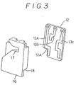
- three fixed contacts 13A, 13B and 13C are, as shown in Fig. 3, provided.
- Each of lead wires 14 to be connected to the corresponding fixed contacts 13A, 13B and 13C are arranged outside through an opening 15 formed in the upper portion of the accommodating portion 10.
- a movable body 16 is disposed between the printed substrate 12 and the detent plate 4 in such a manner that the movable body 16 is accommodated in the accommodating portion 10. As a result, the movable body 16 is enabled to move along the line defined by the shaft 3 and the lock recessed portion 7 in the region between the printed substrate 12 and the detent plate 4.
- a securing groove 17 facing, in Fig. 1, to the right and confronting the securing hole 5 is provided in the upper side portion of the movable body 16 (see Fig. 3).
- the securing groove 17 can tightly accommodate the detent pin 6, and has a gradually-widened inlet portion so as to serve to guide the detent pin 6.
- the movable body 16 is also provided with a securing stepped portion 18 in the right lower portion thereof to correspond to the side surface of the printed substrate 12.
- the movable body 16 is arranged to move between a lock position in the upper portion in Fig. 4 (first pin position) and a lower lock release position (second pin position) together with the detent pin 6 with the detent pin 6 accommodated in the securing groove 17 thereof when the shift lever 1 is positioned at the position "P".
- the detent pin 6 is fitted into the lock recessed portion 7 so that the shift operation of the shift lever 1 is prevented, while the detent pin 6 is separated from the lock recessed portion 7 at the lock release position so that the shifting operation can be enabled.
- a detection switch 20 is formed by the fixed contacts 13A, 13B, and 13C and the movable contacts 19A and 19B.
- the detection switch 20 is connected to an "ON" switch SW1 of the ignition circuit and an ACC switch SW3 (see Fig. 6) of an ignition accessary circuit (ACC circuit) which are operated by an ignition key.
- the structure is so arranged that when the movable body 16 is positioned at the upper locking position, either of the movable contact 19A is, as shown in Fig. 6, brought into contact with the fixed contacts 13B and 13C, while, when the movable body 16 is positioned at the lower lock release position, another movable contact 19B is, as shown in Fig. 7, brought into contact with the fixed contacts 13A and 13C.
- a support plate 21 is fastened and secured to the detent plate 4 in such a manner that the support plate 21 is positioned in front of the holder 9 shown in Fig. 1.
- a first solenoid 22 is secured to the support plate 21.
- An end of a link 23 is, with a pin 26, connected to an actuator 22A of this solenoid 22.
- a cylindrical portion 24 is secured to the intermediate portion of this link 23, and is fitted to the support plate 21 with a pin 25 in such a manner that this cylindrical portion 24 can be rotated.
- Another end of the link 23 is made pass through the opening 11 in the holder 9 and is arranged to be detachable with respect to the securing stepped portion 18 of the movable body 16.
- this link 23 forms a main portion of a locking means for retaining the movable body 16 at the locking position.
- the link 23 is urged by a coil spring 27 wound to the cylindrical portion 24 in the direction at which the link 23 can be engaged with the movable body 16 (in a direction designated by an arrow B).
- the link 23 is urged to turn in the direction designated by the arrow B by the urging force of the coil spring 27, while, when the first solenoid 22 is actuated, the actuator 22A is attracted in the direction designated by an arrow C so that the link 23 is turned in the reverse direction to the arrow B against the urging force of the coil spring 27 so that the link 23 moves away from the movable body 16.
- an end of the first solenoid 22 is earthed to the fixed contact 13B, while another end of the same is earthed, via the brake switch SW2, "ON" switch SW1 to be operated when the engine is supplied with electricity and a car battery BT.
- a movable contact 48 of the "ON" switch SW1 is arranged to coact in synchronization with the operation of the ignition key.
- the brake switch SW2 is switched on when a brake pedal BK is depressed.
- the fixed contact 13C is earthed. Therefore, the first solenoid 22 is, at the lock position shown in Fig. 6, arranged to be operated when the ignition "ON" switch SW1 is switched on and the brake pedal BK is as well depressed.
- a rotor 30 is pivotted in a housing 28 of a steering lock device 29 so that this rotor 30 is arranged to be rotated together with a key rotor (omitted from illustration) to be rotated by an engine key (omitted from illustration).
- Projections 31 are projected from the outer surface of this rotor 30 so as to confront an actuator 32A of a second solenoid 32 secured to the housing 28.
- the actuator 32A is urged in the direction (direction designated by an arrow D) in which the actuator 32A moves away from the projections 31.
- Fig. 8 illustrates a state in which the rotor 30 is positioned at the lock position and the steering device 29 is made lock state.
- the projection 31 confronts the actuator 32A of the second solenoid 32.
- the rotor 30 is turned, in this state, by the key, in the direction designated by an arrow E and is then positioned at the position "ACC" shown in Fig.9, the projection 31 is positioned at the position outside the actuator 32A.
- the ACC switch SW3 shown in Fig. 6 is switched on.
- the rotor 30 is rotated in the direction designated by the arrow E by the key, the engine is brought to an operative state and the "ON" switch SW1 is turned on.
- the actuator 32A of the second solenoid 32 is, as shown in Fig. 8, urged by a compression coil spring 33 in the direction designated by the arrow D when the second solenoid 32 is turned off so that the actuator 32A is positioned outside the rotating range of the projection 31.
- the actuator 32A when the actuator 32A is turned on, the actuator 32 A projects in the reverse direction to the arrow D against the compression coil spring 33 so that the actuator 32A is positioned within the rotating range of the projection 31 shown in Fig. 9.
- an end of the second solenoid 32 is connected to the fixed contact 13A of the detection switch 20, while another end of the same is earthed via the ACC switch SW3 and the car battery BT. Therefore, the structure is so constituted that when the ACC switch SW3 is switched on at the lock release position shown in Fig. 7, the second solenoid 32 is operated.
- the ignition ACC circuit is in OFF state, both the switches SW1 and SW3 are in OFF state, and the first and second solenoids 22 and 32 are also in OFF state respectively. Since the first solenoid 22 is in OFF state, the link 23 is rotated in the direction designated by the arrow B so that a front end portion (lock means) 23A of the link 23 is, as shown by a continuous line shown in Fig. 4, engaged with the securing stepped portion 18 of the movable body 16. As a result, the downward movement of the movable body 16 is prevented.
- the actuator 32A thereof is positioned at outside the rotation range of the projection 31 by the urging force of the compression coil spring 33 so that the rotation of the rotor 30 in the direction designated by the arrow E is allowed to be performed.
- the first solenoid 22 is, via the fixed contacts 13B and 13C and the movable contact 19A (see Fig. 6) of the detection switch 20, connected to the car battery BT. Therefore, the first solenoid 22 is turned on. Therefore, the actuator 22A of the solenoid 22 is attracted in the direction designated by the arrow C. In accordance with this operation, the link 23 is rotated in the reverse direction to the arrow B so that the front end portion 23A is brought into state where the front end portion 23A is, as shown by an alternate long and two dashed line shown in Fig. 4, separated from the securing stepped portion 18 of the movable body 16.
- the second solenoid 32 When the movable body 16 is positioned at the lock release position, the second solenoid 32 is turned on since the movable contact 19B of the detection switch 20 is, as shown in Fig. 7, brought into contact with the fixed contacts 13A and 13C. On the other hand, the first solenoid 22 is turned off since the movable contact 19A is moved away from the fixed contact 13B.
- the actuator 32A thereof projects in the reverse direction to the arrow D against the compression spring 33 so that the same is positioned within the rotation range of the projection 31.
- the rotation of the rotor 30 to the lock position is also prevented. Therefore, it becomes impossible to make the steering lock device 29 lock state.
- the detent pin 6 Since the movable body 16 is positioned at the lock release position at the position "P", the detent pin 6 is introduced into the securing groove 17 in the movable body 16 by the shifting operation of the shift lever 1. Since the movable body 16 is positioned at the lock release position when the shift lever 1 is positioned other than the position "P", the detent pin 6 can be immediately engaged with the movable body 16 when the shift lever 1 returns to the position "P". When the movement of the detent pin 6 is controlled by the direct engagement of the front end portion 23A of the link 23 with the detent pin within the securing groove 17, the link front end portion 23A is introduced into the securing stepped portion 18 if the shift lever 1 is positioned other than the position "P".
- the detent pin 6 is moved upward together with the movable body 16 so as to be engaged with the lock recessed portion 7, and so as to make the movable body 16 locate at the lock position.
- the movable body 16 is positioned at the lock position, the front portion 23A of the link 23 urged in the direction designated by the arrow B is engaged with the securing stepped portion 18 in the movable body 16 so that downward movement of the movable body 16 is prevented (see Fig. 4).
- the movable contact 19B of the detection switch 20 is separated from the fixed contact 13A (see Fig. 6), causing for the second solenoid 32 to be turned off.
- the actuator 32A is moved to the direction designated by the arrow D and the same is positioned outside the rotation range of the projection 31.
- the rotor 30 can be rotated to the locking position by the key in the reverse direction as designated by the arrow E.
- the projection 31 is, as shown in Fig. 8, brought into state where the same confronts the actuator 32A of the second solenoid 32.
- the steering lock device 29 is brought into lock state, the insertion and separation of the key is simultaneously allowed.
- electricity supply to the engine is stopped, and the ACC circuit is brought into an OFF state.
- the detection switch 20 to be operated by the movement of the movable body 16 is provided, the movable body 16 being moved in synchronization with the movement of the detent pin 6 in such a manner that the movable body 16 is engaged with the detent pin 6 when the shift lever 1 is positioned at the position "P". Therefore, the fact that the detent pin 6 has been engaged with the lock recessed portion 7 of the detent plate 4 can be detected by the detection switch 20. As a result, the fact that the shift lever 1 has been positioned at a specific non-drive position "P" can be more assuredly detected than the device which detects the movement position of a shift lever.
- Figs. 10 and 11 illustrate a second embodiment of the present invention.
- the difference from the first embodiment lies in that: two side portions of a holder 35 are secured to the detent plate 4.
- a movable body 34 is disposed between this holder 35 and the detent plate 4 so as to be slid between the lock position (see Fig. 10) and the lock release position (Fig. 11).
- a projection 37 is provided, as a result of which a partial thick portion is formed.
- a limit switch 38 is positioned corresponding to the projection 37, and is secured to the holder 35.
- An abutting arm 39 having an elasticity is provided at the position confronting an operating member 38A projecting from the limit switch 38.
- the detection switch 38 is connected to the first solenoid 32 according to the first embodiment on the steering lock device side via a lead wire (omitted from illustration).
- a lock lever 40 is rotatably provided for the detent plate 4 with a pin 41.
- the lock lever 40 includes a securing arm portion 43 which is arranged to be engaged with and separated from the securing stepped portion 42 of the movable body 34.
- a connecting arm portion 44 projecting from this lock lever 40 is connected to the actuator 22A of the solenoid 22 with the wire 45, and the same is urged in the direction designated by an arrow F by a twisted coil spring (omitted from illustration) wound to the pin 41.
- the connecting arm portion 44 is arranged to be rotated in the reverse direction to the arrow F when the solenoid 22 is supplied with electricity.
- the neutral switch 54 is, as shown in Fig. 10, added to the operation circuit of the solenoid 22 so that the parking position of the shift lever is detected. That is, an end of the first solenoid 22 is earthed, while another end of the same is connected to an end of an AND device 52. A terminal 52A at the other end of this AND device 52 is earthed via the brake switch SW2, the "ON" switch SW1 to be operated when the engine is supplied with electricity, and the car battery BT. Another terminal 52B at the other end of the AND device 52 is connected to the P-contact 54A of the above-described neutral switch 54.
- the terminal 52B is arranged to be connected to the car battery only when the shift lever 1 is positioned at the parking position, that is, when the engine output is not transmitted to the wheels.
- the AND device 52 is further arranged in such a manner that electricity is supplied to the solenoid 22 when the brake pedal BK is footed, causing for the switch SW2 to be switched on, and the switch SW1 is turned on at which the engine is operated. In this state, a circuit for supplying electricity to the engine is omitted from illustration.
- the neutral switch 54 is arranged to light the position indicator lamps "LP”, “LR”, “LN”, “LD”, “L2”, and "LL” in accordance with the position of the operated shift lever 1.
- the movable body 34 is positioned in the lower lock release position when the shift lever 1 is positioned at the position other than the position "P" and the front end portion of the securing arm portion 43 of the lock lever 40 is positioned in contact with the left end portion of the movable body 34 (see Fig. 11).
- the detection switch 38 is turned on since the operation member 38A of the detection switch 38 is abutted by the projection 37 of the movable body 34 via the abutting member 39.
- the solenoid 32 on the steering lock device side is turned on, and the mode change of the steering lock device from lock release state to lock state is prevented.
- the detent pin 6 When the shift lever 1 is shifted to the position "P" with the pressure to the button 8 retained, the detent pin 6 is, as shown in Fig. 11, engaged with the securing groove 17 of the movable body 34. In this state, when the pressure applied to the button 8 is released, the detent pin 6 is, together with the movable body 34, moved upward, as a result of which, the same is, as shown in Fig. 10, engaged with the lock recessed portion 7. Furthermore, the movable body 34 is positioned at the lock position. As a result, since the pressure of the projection 37 of the movable body 34 to the abutting member 39 is released, the detection switch 38 is turned off.
- the solenoid 32 on the steering lock device is turned off, and the steering lock device is allowed to be changed from lock release state to lock state.
- the downward movement of the movable body 34 is prevented by the engagement of the securing arm 43 of the lock lever 40 with the securing stepped portion 42 of the movable body 34. If the engine is operated (if the switch SW1 is switched on) and the brake pedal BT is footed in this state, the lock lever 40 is rotated in the reverse direction to the arrow F since the switch SW2 is switched on, as a result of which, the downward movement of the movable body 34 is allowed.
- a general slide switch or contact switch can be used only satisfying the fact that the same is operated in accordance with the movement of the movable body.
- a third embodiment of the present invention will be described with reference to Figs. 12 to 16.
- This third embodiment is characterized in that in particular the switch portion disclosed in the first embodiment is changed for the purpose of making the manufacture of the device easy. That is, it is preferable in the first embodiment, the switching timing from the lock position shown in Fig. 6 to the lock release position shown in Fig. 7 is arranged in such a manner that the detent pin 6 is at the central portion in the direction of the depth of the lock recessed portion 7. However, assuming a case where this switching timing is slipped toward the groove bottom of the lock recessed portion 7, the movable body is enabled to be moved when the driver boards the vehicle and then foots, in the state shown in Fig.
- the above-described desired operation can be achieved only by securing the manufacturing and mounting dimensional relationship between the fixed contacts and the movable contacts of the detection switch 20, and the manufacturing and mounting tolerance between the movable body 16 and the link 23.
- the switching timing of the detection switch 20 needs to be performed correctly at the intermediate position of the short vertical stroke of the detent pin 6.
- the third embodiment to be described hereinafter is capable of overcoming this factor.
- a movable body 316 according to this embodiment is slidably guided in the direction similar to the first embodiment by way of a pin 311 projected from the detent plate 4 is inserted into a pair of elongated holes 310 formed in the lengthwise direction.
- a cut 313 On one side in the lower portion of a movable body 316 is formed a cut 313 which is arranged to correspond to a locking link 323.
- the locking link 323 is pivotted by the detent plate 4 at the central portion thereof by a pin 317.
- An end of the locking link 323 is connected to the actuator 22A of the first solenoid 22, while another end of the same is urged in the direction in which the same is engaged with the cut 313 in the movable body 316 by a compression spring 327.
- the locking link 323 and the movable body 316 are preferable to be made in such a manner that either one of them is made of a synthetic resin while another one is made of a metal considering the abrasion at the time of contact.
- An arm 314 projects over the another end portion in the lower position of the movable body 316 so as to be engaged with a slider 320A of a slide switch 320. As a result, the movement of the movable body can be transmitted to the slider.
- the structure of the slide switch 320 is, as shown in Fig. 14, arranged in such a manner that a first fixed contact 313A and a second fixed contact 313B are in parallel to each other and set off each other in the lengthwise direction on the two sides of a common fixed contact 313C.
- a first movable contact 319A and a second movable contact 319B connected to the slider 320A shown in Fig. 12 respectively connect between the common fixed contact 313C and the second fixed contact 313B, and between the common fixed contact 313C and the first fixed contact 313A.
- These common fixed contact 313C and the first and second fixed contacts, 313A, and 313B are arranged to be the wiring structure in accordance with the three fixed contacts 13C, 13A, and 13B described in the first embodiment (see Fig. 6).
- the first and second movable contacts 319A and 319B are brought to state shown by a continuous line in Fig. 14.
- the first movable contact 319A turns on the fixed contact 313C and the second movable contact 313B, while when the movable body 31B is brought to the lock release position, the same becomes state designated by an imaginary line shown in Fig. 14. Therefore, the second movable contact 319B turns on the common and first fixed contacts 313C and 313A.
- the movable body 316 is made movable along the line connecting the shaft 3 and the lock recessed portion 7 by inserting the pin 311 provided for the detent plate 4 into the guide groove 310 which is formed vertically in the left portion of the movable body 316.
- the movable body 316 is provided with a cut portion 313 in the left lower portion thereof and is provided with a projection 314 projecting to the right in the lower portion thereof.
- a first switch portion 300A for controlling the first solenoid 22 is formed by the common fixed contact 313C, the first fixed contact 313A and the first movable contact 319A which is arranged to be contact and separated from the former two contacts. Furthermore, a second switch portion 300B for controlling the second solenoid 32 is formed by the common fixed contact 313C, second fixed contact 313A and the second movable contact 319B which is arranged to be contact and separated from the former contacts.
- the first switch portion 300A has a switching point 357 thereof that is positioned (see Fig.
- the first switch portion 300A has a switching point 357 at the position where the movable body 316 is free from the restriction of the link 323.
- the first switch portion 300A is arranged to be switched on when the first movable contact 319A is positioned in a region D which is upper than the switching point 357.
- the first switch portion 300A is also arranged to be switched off when the first movable contact 319A is positioned lower than the region D.
- the second switch portion 300B has a switching point 358 thereof at the position upper than the position where the cut portion 313 of the movable body 316 is brought into contact with the front end of the link 323, that is, the second switch portion 300B has the switching point thereof at the position where the detent pin 6 can be assuredly engaged with the lock recessed portion 7 and thereby the movable body 316 can be restricted by the link 323.
- the second switch portion 300A is arranged to be actuated at the position at which the second movable contact 319B is position in a region E which is lower than this switching point 358, while the same is arranged to be switched off when the second movable contact 319B is positioned upper than the switching point 358.
- the switching point 357 of the first switch portion 300A and the switching point 358 of the second switch portion 300B are positioned in a vertically set off manner.
- the region D in which the first switch portion 300A can be actuated and the region E in which the second switch portion 300B can be actuated are overlapped in the region F disposed between the two switching points 357 and 358.
- the actuator 32A of this second solenoid 32 is, as shown in Fig. 8, positioned outside the rotating range of the projection 31 by the urging force from the compression coil spring 33 so that the rotation of the rotor 30 in the direction designated by the arrow E is allowed to be performed.
- the actuator 22A of the first solenoid 22 is attracted in the direction designated by the arrow C.
- the link 323 is rotated in the reverse direction to the arrow B so that the front end thereof is, as designated by an alternated long and two short dashes line shown in Fig. 12, brought to state where the same is retracted from the cut portion 313 of the movable body 316.
- the slider 320A of the switch 320 is moved downward in synchronization with the downward movement of the movable body 316. And also in synchronization with this movement, the first and second movable contacts 319A and 319B are moved lower from the position designated by the continuous line shown in Fig. 14.
- the second movable contact 319B reaches the switching point 358 as shown by the continuous line in Fig. 16, the second switch portion 300B is switched from non-actuated state to operation state.
- the second solenoid 32 on the steering lock device 29 side shown in Fig. 9 is turned on, causing for the actuator 32A of the second solenoid 32 to project in the reverse direction to the arrow D and causing for the same to be positioned within the rotating range of the projection 31.
- the link 323 is rotated in the direction designated by the arrow B by the urging force from the compression coil spring 327 regardless of the state of the brake pedal, and the front end of the link 323 is brought into contact with the left end in the upper portion of the cut portion 313. Therefore, the state of 323 is maintained even if the movable contact 316 is moved to the lock release position (see Fig. 13).
- the first switch portion 300A is switched to operation state.
- the link 323 is rotated in the reverse direction to the arrow B, while if the brake pedal is not footed, the link 323 is retained as it has been rotated in the direction designated by the arrow B.
- the movable body 316 is further moved upward, the front end of the link 323 is introduced into the cut portion 313.
- the second switch portion 300B is switched to non-operation state.
- the second solenoid 32 is turned off, and the actuator 32A thereof is moved in the direction designated by the arrow D and is positioned outside the rotating range of the projection 31.
- the rotation of the projection 31 in the reverse direction to the arrow E is allowed to be performed, the rotor 30 can be, by the key, rotated in the reverse direction designated by the arrow E so as to make the same position at the lock position.
- the switching point 357 of the first switch portion 300A for controlling the first solenoid 22 and the switching point 358 of the second switch portion 300B for controlling the second solenoid 32 are, as described above, disposed in an offset manner to each other. Furthermore, the region D at which the first switch portion 300A is actuated and the region E at which the second switch portion 300B is actuated are overlapped at the position between the two switching points 357 and 358. As a result of the thus-arranged structure, even if a mounting error occurs for the first and second switch portions 300A and 300B, such error can be absorbed. Therefore, control of the first and second solenoids 22 and 32 can be made free from a problem. Therefore, the mounting of these first and second switch portions 300A and 300B can be easily conducted.
- Fig. 17 illustrates a device according to a fourth embodiment of the present invention and which corresponds to the state shown in Figs. 6 and 7.
- Fig. 17 clearly illustrates the state where a region I in which the movable contact 19A turns on the fixed contacts 13B and 13C and a region J in which the movable contact 19B turns on the fixed contacts 13A and 13C are overlapped over a length K. From which, the similar effect obtained by the third embodiment can be obtained.
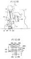
- Figs. 18 and 19 illustrate a fifth embodiment of the present invention. Only the portion different from the third embodiment will be described.
- the actuator 22A of the first solenoid 22 faces to the right in Fig. 18.
- the lower end portion of the link 323 which serves as a lock lever is rotatably connected to the actuator 22A.
- the link 323 is urged in the direction designated by an arrow L by the compression coil spring 327 as shown in Fig. 18 when the first solenoid 22 is turned off.
- the front end of this link 323 is positioned outside the cut portion 313 of the movable body 316.
- the actuator 22A is attracted in the direction designated by an arrow M.
- the link 323 is rotated in the reverse direction designated by the arrow L as designated by an alternate long and two short dashes line so that the front end thereof is introduced into the cut portion 313 of the movable body 316.
- the first fixed contact 313A is, different from the third embodiment (see Fig. 14), disposed on one side in the lengthwise direction and on the same side as the second fixed contact 313B.
- the length of the first fixed contact 313A is made shorter than that of the second fixed contact 313B (region N) by length P, and its operation range is arranged to be length O.
- the actuator 22a is attracted in the direction designated by the arrow M, causing the link 323 to be rotated in the reverse direction to the arrow L.
- the current is changed to a retaining current by a timer (omitted from illustration).
- the link 323 is retained at the position after it has been rotated in the direction designated by the arrow L.
- the shift lever 1 can be released from lock state by operating the button 8 of the shift lever 1.
- the button is pushed without footing the brake pedal, the movable body 316 can be moved downward only by the contact of the front end thereof with the link 323.
- the second switch portion 300B is turned off as shown by an alternate long and a dash line, the turning-on state of the first switch portion 300A is retained. Therefore the turning-on state of the first solenoid is retained so that the shift lever 1 cannot be released from the lock state.
- the second solenoid 32 on the steering lock device 29 side is turned off when the second movable contact 319B of the second switch portion 300B is positioned upper than the switching point 358. As a result, the steering lock device 29 is allowed to be locked. On the other hand, when the second movable contact 319B is positioned lower than the switching point 358, the second solenoid 32 is turned on. As a result, the steering lock device 29 is prevented from being brought to lock state.
- the switching point 357 of the first switch portion 300A and the switching point 358 of the second switch portion 300B are disposed in a vertical offset manner, and the region N in which the first switch portion 300A is actuated and the region O in which the second switch portion 300B is actuated are overlapped in the region P.
- a mounting error for the first and second switch portions 300A and 300B can be absorbed. Therefore, the control of the first solenoid 22 can be made free from a problem, and mounting of the switch can be easily conducted.
- the first solenoid 22 when the movable body 316 is moved upward from the lock release position to the lock position, the first solenoid 22 is arranged to be turned on at the switching point 358 of the second switch portion 300B as an alternative to the switching point 357 of the first switch portion 300A. Therefore, when the first solenoid 22 is turned on, the link 323 can be assuredly introduced into the cut portion 313 of the movable body 316, causing for the movable body 316 to be assuredly held.
- the front end of the link 323 is brought into contact with the top edge of the cut portion 313 in the movable body, causing for a fear that the current is switched to the retaining current. It leads to a fact that the link 323 cannot be rotated in the reverse direction to the arrow L even if the movable body 316 is then moved further upward. Therefore, there arises a fear that the restriction of the movable body 316 by the link 323 becomes impossible. However, such fear can be clearly overcome according to the fifth embodiment.
- the movable body may be directly restricted by the first solenoid as an alternative to the manner that the link is used.
- a motor or the like can be used as an alternative to the solenoid.
Landscapes
- Engineering & Computer Science (AREA)
- General Engineering & Computer Science (AREA)
- Mechanical Engineering (AREA)
- Chemical & Material Sciences (AREA)
- Combustion & Propulsion (AREA)
- Transportation (AREA)
- Arrangement Or Mounting Of Control Devices For Change-Speed Gearing (AREA)
- Control Of Transmission Device (AREA)
- Mechanical Control Devices (AREA)
- Braking Elements And Transmission Devices (AREA)
Abstract
Description
- The present invention relates to a transmission operating apparatus for an automatic transmission according to the preamble of
claim 1. - A Conventional apparatus as disclosed in EP-A-0 246 353 is arranged in such a manner that, when a shift lever for operating an automatic transmission is moved from a parking position to another shift position, the shift lever cannot be moved if a special operation is not performed by a driver.
- There, a detection means is disclosed detecting the "P" position of a shift lever. If the shift lever is in the "P" position, a movable body is swung by means of a lock means in order to lock the shift lever in the "P" position. The lock means can exclusively be unlocked by operating the brake, so that the brake pedal has to be depressed to move the shift lever out of its "P" position. The movement of a detent pin arranged on the shift lever and fixing or releasing this by means of the shifting gate is not detected by the detection means. Thus, in unfavourable operating positions of the detent pin and the lock means, it is possible to move the shift lever out of the supposedly chosen "P" position without first depressing the brake pedal, as not the position of the detent pin but only the position of the shift lever is detected. Neither does this device take into account that there is a key in the ignition lock.
- It is the object of the present invention to create a transmission operating apparatus according to the preamble of
claim 1, as known from EP-A-0 246 353 in which the operating safety has been improved. - This task is solved by the features in the characterizing part of
claim 1. - According to the invention, the position of the detent pin is detected which is directly coupled with the movable body in the "P" position of the shift lever. There are no intermediate positions of the shift lever or the detent pin resp. in which the detection means report a locked "P" position and the detent pin is not completely locked. By the direct detection of the position of the detent pin or the movable body resp., the mechanical lock is always exactly controllable.
- It is to be seen as particular advantage that the position of the detent pin is exactly determined via the movable body and the ignition key cannot be removed when the detent pin (Fig. 6) is positioned accordingly. On the other hand, the ignition key cannot start the motor either as long as the shift lever is not brought into the "P" position and the detection means detect that the detent pin is in its locking position.
- Fig. 1 is an exploded perspective view of a first embodiment of a transmission operating apparatus in the present invention;
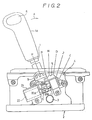
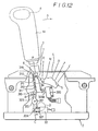
- Fig. 2 is a partially broken side elevational view illustrating the first embodiment of the present invention;
- Fig. 3 is a perspective view of a movable body and a printed substrate;
- Fig. 4 is a side elevational view of the movable body and the detent plate at lock position;
- Fig. 5 is a side elevational view of the movable body and the detent plate at lock release position;
- Fig. 6 is a front elevational view of a detection switch at the lock position;
- Fig. 7 is a front elevational view of the detection switch at the lock release position;
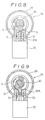
- Fig. 8 is a cross-sectional view of a steering lock device under the lock condition;
- Fig. 9 is a cross sectional view of the steering lock device under an ACC condition;
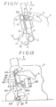
- Fig. 10 is a side elevational view of an apparatus at a lock position according to a second embodiment in the present invention and corresponding to Fig. 4;
- Fig. 11 is a side elevational view of the apparatus of the second embodiment at a lock released position moved from the position shown in Fig. 10;
- Fig. 12 is a side elevational view of an apparatus of a third embodiment in the present invention and corresponding to Fig. 2;
- Fig. 13 is a side elevational view of the apparatus at a lock release position according to the third embodiment;
- Fig. 14 is a front elevational view of a detection switch according to the third embodiment;
- Fig. 15 is a side elevational view the apparatus of a lock position according to the third embodiment;
- Fig. 16 is a schematic explanatory view illustrating an operation of the detection switch shown in Fig. 14;
- Fig. 17 is a front elevational view of a detection switch according to a fourth embodiment in the present invention;
- Fig. 18 is a side elevational view of an apparatus of a fifth embodiment in the present invention and corresponding to Fig. 12; and
- Fig. 19 is a front elevational view of a detection switch of the fifth embodiment in the present invention.
- A first embodiment of the present invention will now be described with reference to Figs. 1 to 9.
- As shown in Figs. 1 and 2, a
shift lever 1 is provided in such a manner that the same can be moved in the direction designated by an arrow A and also in the reverse direction of the arrow A relative to ashaft 3 secured to aframe 2, the shift lever being used for controlling an hydraulic circuit for a transmission (omitted from illustration). A saw-shaped securing hole 5 extending along the direction of the movement of theshift lever 1 is formed in adetent plate 4 which is provided to stand from theframe 2. The securinghole 5 is arranged, in association with adetent pin 6, to limit the range through which the shift lever moves when theshift lever 1 is shifted to a parking mode "P", reverse mode "R", neutral transmission mode "N", automatic transmission mode "D", "2" when the transmission is at the second gear, and "L" when the transmission is at the low gear. A lock recessedportion 7 which is in the form of a relatively deep cut in thesecuring hole 5 is formed in thesecuring hole 5 at the position corresponding to the position "P" at which the vehicle is not driven and is a specific non-drive position. Thedetent pin 6 perpendicularly projects from theshift lever 1, is arranged in such a manner that the same can be moved in the axial direction of theshift lever 1, and also is urged in the direction of aknob 1A of theshift lever 1. Thedetent pin 6 is arranged in such a manner: when abutton 8 provided on theknob 1A of theshift lever 1 is pressed, thedetent pin 6 is moved downward so that the engagement of the same with each of the engagement surfaces corresponding to the positions is released. On the other hand, when the pressure applied to thebutton 8 is released, thedetent pin 6 moves upward so that thedetent pin 6 is made engage with one of an engagement surface in the securinghole 5. - A
holder 9 is fastened and secured to the side surface of thedetent plate 4. Thisholder 9 is provided with anaccommodating portion 10 having an opening in the side surface thereof and which confronts thedetent plate 4 and another opening in the lower surface thereof. Furthermore, theaccommodating portion 10 is provided with an opening 11 in the right lower portion thereof. In addition, a printedcircuit 12 is fitted into and secured to the inner surface of theaccommodating portion 10. Acut portion 12A is formed in the printedcircuit 12 at the position corresponding to the position of the opening 11. On the side surface of the printedcircuit 12 on the confronting surface to thedetent plate 4, threefixed contacts lead wires 14 to be connected to the correspondingfixed contacts opening 15 formed in the upper portion of theaccommodating portion 10. - A
movable body 16 is disposed between the printedsubstrate 12 and thedetent plate 4 in such a manner that themovable body 16 is accommodated in theaccommodating portion 10. As a result, themovable body 16 is enabled to move along the line defined by theshaft 3 and the lock recessedportion 7 in the region between the printedsubstrate 12 and thedetent plate 4. - A
securing groove 17 facing, in Fig. 1, to the right and confronting the securinghole 5 is provided in the upper side portion of the movable body 16 (see Fig. 3). Thesecuring groove 17 can tightly accommodate thedetent pin 6, and has a gradually-widened inlet portion so as to serve to guide thedetent pin 6. Themovable body 16 is also provided with a securingstepped portion 18 in the right lower portion thereof to correspond to the side surface of the printedsubstrate 12. - The
movable body 16 is arranged to move between a lock position in the upper portion in Fig. 4 (first pin position) and a lower lock release position (second pin position) together with thedetent pin 6 with thedetent pin 6 accommodated in thesecuring groove 17 thereof when theshift lever 1 is positioned at the position "P". At the lock position, thedetent pin 6 is fitted into the lock recessedportion 7 so that the shift operation of theshift lever 1 is prevented, while thedetent pin 6 is separated from the lock recessedportion 7 at the lock release position so that the shifting operation can be enabled. On the side surface of themovable body 16 confronting the printedsubstrate 12, twomovable contacts fixed contacts movable body 16 is moved. As a result, adetection switch 20 is formed by thefixed contacts movable contacts detection switch 20 is connected to an "ON" switch SW1 of the ignition circuit and an ACC switch SW3 (see Fig. 6) of an ignition accessary circuit (ACC circuit) which are operated by an ignition key. - The structure is so arranged that when the
movable body 16 is positioned at the upper locking position, either of themovable contact 19A is, as shown in Fig. 6, brought into contact with thefixed contacts movable body 16 is positioned at the lower lock release position, anothermovable contact 19B is, as shown in Fig. 7, brought into contact with thefixed contacts - A
support plate 21 is fastened and secured to thedetent plate 4 in such a manner that thesupport plate 21 is positioned in front of theholder 9 shown in Fig. 1. Afirst solenoid 22 is secured to thesupport plate 21. An end of alink 23 is, with apin 26, connected to anactuator 22A of thissolenoid 22. Acylindrical portion 24 is secured to the intermediate portion of thislink 23, and is fitted to thesupport plate 21 with apin 25 in such a manner that thiscylindrical portion 24 can be rotated. Another end of thelink 23 is made pass through the opening 11 in theholder 9 and is arranged to be detachable with respect to the securing steppedportion 18 of themovable body 16. Therefore, thislink 23 forms a main portion of a locking means for retaining themovable body 16 at the locking position. Thelink 23 is urged by acoil spring 27 wound to thecylindrical portion 24 in the direction at which thelink 23 can be engaged with the movable body 16 (in a direction designated by an arrow B). When thefirst solenoid 22 is not actuated, thelink 23 is urged to turn in the direction designated by the arrow B by the urging force of thecoil spring 27, while, when thefirst solenoid 22 is actuated, theactuator 22A is attracted in the direction designated by an arrow C so that thelink 23 is turned in the reverse direction to the arrow B against the urging force of thecoil spring 27 so that thelink 23 moves away from themovable body 16. - As shown in Fig. 6, an end of the
first solenoid 22 is earthed to the fixedcontact 13B, while another end of the same is earthed, via the brake switch SW2, "ON" switch SW1 to be operated when the engine is supplied with electricity and a car battery BT. Amovable contact 48 of the "ON" switch SW1 is arranged to coact in synchronization with the operation of the ignition key. The brake switch SW2 is switched on when a brake pedal BK is depressed. The fixedcontact 13C is earthed. Therefore, thefirst solenoid 22 is, at the lock position shown in Fig. 6, arranged to be operated when the ignition "ON" switch SW1 is switched on and the brake pedal BK is as well depressed. - On the other hand, as shown in Fig. 8, a
rotor 30 is pivotted in ahousing 28 of asteering lock device 29 so that thisrotor 30 is arranged to be rotated together with a key rotor (omitted from illustration) to be rotated by an engine key (omitted from illustration).Projections 31 are projected from the outer surface of thisrotor 30 so as to confront anactuator 32A of asecond solenoid 32 secured to thehousing 28. Theactuator 32A is urged in the direction (direction designated by an arrow D) in which theactuator 32A moves away from theprojections 31. Fig. 8 illustrates a state in which therotor 30 is positioned at the lock position and thesteering device 29 is made lock state. In this state, theprojection 31 confronts theactuator 32A of thesecond solenoid 32. When therotor 30 is turned, in this state, by the key, in the direction designated by an arrow E and is then positioned at the position "ACC" shown in Fig.9, theprojection 31 is positioned at the position outside theactuator 32A. In this state, the ACC switch SW3 shown in Fig. 6 is switched on. Furthermore, when therotor 30 is rotated in the direction designated by the arrow E by the key, the engine is brought to an operative state and the "ON" switch SW1 is turned on. - On the other hand, the
actuator 32A of thesecond solenoid 32 is, as shown in Fig. 8, urged by acompression coil spring 33 in the direction designated by the arrow D when thesecond solenoid 32 is turned off so that theactuator 32A is positioned outside the rotating range of theprojection 31. On the other hand, when theactuator 32A is turned on, theactuator 32 A projects in the reverse direction to the arrow D against thecompression coil spring 33 so that theactuator 32A is positioned within the rotating range of theprojection 31 shown in Fig. 9. - As shown in Fig. 6, an end of the
second solenoid 32 is connected to the fixedcontact 13A of thedetection switch 20, while another end of the same is earthed via the ACC switch SW3 and the car battery BT. Therefore, the structure is so constituted that when the ACC switch SW3 is switched on at the lock release position shown in Fig. 7, thesecond solenoid 32 is operated. - An operation of the above-described structure will be described hereinafter. When the
shift lever 1 is positioned at the position "P", therotor 30 is at the lock position, and thesteering device 29 is made lock state, thedetent pin 6 is, as shown in Fig.4, engaged with the lock recessedportion 7 in the securinghole 5 in thedetent plate 4, and the securinggroove 17 of themovable body 16 is engaged with thedetent pin 6. As a result, themovable body 16 is positioned at the upper lock position. - In this state, the ignition ACC circuit is in OFF state, both the switches SW1 and SW3 are in OFF state, and the first and
second solenoids first solenoid 22 is in OFF state, thelink 23 is rotated in the direction designated by the arrow B so that a front end portion (lock means) 23A of thelink 23 is, as shown by a continuous line shown in Fig. 4, engaged with the securing steppedportion 18 of themovable body 16. As a result, the downward movement of themovable body 16 is prevented. - On the other hand, since the
second solenoid 32 is in OFF state, theactuator 32A thereof is positioned at outside the rotation range of theprojection 31 by the urging force of thecompression coil spring 33 so that the rotation of therotor 30 in the direction designated by the arrow E is allowed to be performed. - Therefore, in this state, the insertion and coming off of the key is allowed when the
rotor 30 is positioned at the lock position, while therotor 30 is allowed to be rotated between the lock position and the operation position. - When the
rotor 30 is rotated in the direction designated by the arrow E and thereby positioned at the operation position in this state, theprojection 31 moves to outside the position confronting theactuator 32A of thesecond solenoid 32 and thesteering lock device 29 is brought into lock release state. In addition, the ACC switch SW3 is switched on, causing for the ACC circuit to be brought to operative state. Furthermore, the key is turned in the direction designated by the arrow E to be positioned at the "ON" position, causing for the engine to be started, and as well causing for the ON switch SW1 to be switched on. When the brake pedal BK is, in this state, depressed, theswitch SW 2 arranged to act in synchronization with the brake pedal BK is switched on. As a result, thefirst solenoid 22 is, via the fixedcontacts movable contact 19A (see Fig. 6) of thedetection switch 20, connected to the car battery BT. Therefore, thefirst solenoid 22 is turned on. Therefore, theactuator 22A of thesolenoid 22 is attracted in the direction designated by the arrow C. In accordance with this operation, thelink 23 is rotated in the reverse direction to the arrow B so that thefront end portion 23A is brought into state where thefront end portion 23A is, as shown by an alternate long and two dashed line shown in Fig. 4, separated from the securing steppedportion 18 of themovable body 16. - When the
button 8 of theshift lever 1 is, in this state, pushed, thedetent pin 6 and themovable body 16 which is engaged with thedetent pin 6 are moved downward so that themovable body 16 is, as shown in Fig.5, positioned at the lock release position. As a result, by operating theshift lever 1 in the direction designated by the arrow A, thedetent pin 6 is separated from the securinggroove 17. As a result, theshift lever 1 can be shifted from the position "P" to another position. - When the
movable body 16 is positioned at the lock release position, thesecond solenoid 32 is turned on since themovable contact 19B of thedetection switch 20 is, as shown in Fig. 7, brought into contact with the fixedcontacts first solenoid 22 is turned off since themovable contact 19A is moved away from the fixedcontact 13B. When thesecond solenoid 32 is turned on, theactuator 32A thereof projects in the reverse direction to the arrow D against thecompression spring 33 so that the same is positioned within the rotation range of theprojection 31. As a result of the prevention of the rotation of theprojection 31 in the reverse direction to the arrow E, the rotation of therotor 30 to the lock position is also prevented. Therefore, it becomes impossible to make thesteering lock device 29 lock state. - On the other hand, when the
solenoid 22 is turned off, thelink 23 is turned in the direction designated by the arrow B by the urging force of the twistedcoil spring 27 so that thefront end portion 23A thereof is brought into contact with the side surface of themovable body 16. Even if the brake pedal BK is depressed in this state, thefirst solenoid 22 is remained its OFF state and the state of thelink 23 cannot be changed. - Next, the case in which the
shift lever 1 is shifted from the position other than the position "P" to the position "P" with pushing thebutton 8 retained will be described. - Since the
movable body 16 is positioned at the lock release position at the position "P", thedetent pin 6 is introduced into the securinggroove 17 in themovable body 16 by the shifting operation of theshift lever 1. Since themovable body 16 is positioned at the lock release position when theshift lever 1 is positioned other than the position "P", thedetent pin 6 can be immediately engaged with themovable body 16 when theshift lever 1 returns to the position "P". When the movement of thedetent pin 6 is controlled by the direct engagement of thefront end portion 23A of thelink 23 with the detent pin within the securinggroove 17, the linkfront end portion 23A is introduced into the securing steppedportion 18 if theshift lever 1 is positioned other than the position "P". As a result, the movement of thedetent pin 6 to the position "P" is prevented, causing a necessity of an operation to be performed that thesolenoid 22 is moved before the movement of theshift lever 1 to the position "P" in order to separate thelink front portion 23A from the securing steppedportion 18. - When the pressure applied to the
button 8 is released after theshift lever 1 has been moved to the position "P", thedetent pin 6 is moved upward together with themovable body 16 so as to be engaged with the lock recessedportion 7, and so as to make themovable body 16 locate at the lock position. As described above, themovable body 16 is positioned at the lock position, thefront portion 23A of thelink 23 urged in the direction designated by the arrow B is engaged with the securing steppedportion 18 in themovable body 16 so that downward movement of themovable body 16 is prevented (see Fig. 4). Furthermore, themovable contact 19B of thedetection switch 20 is separated from the fixedcontact 13A (see Fig. 6), causing for thesecond solenoid 32 to be turned off. As a result, theactuator 32A is moved to the direction designated by the arrow D and the same is positioned outside the rotation range of theprojection 31. When this state is realized, since the rotation of theprojection 31 in the reverse direction to the arrow E is allowed, therotor 30 can be rotated to the locking position by the key in the reverse direction as designated by the arrow E. When therotor 30 is rotated to the lock position, theprojection 31 is, as shown in Fig. 8, brought into state where the same confronts theactuator 32A of thesecond solenoid 32. Furthermore, when thesteering lock device 29 is brought into lock state, the insertion and separation of the key is simultaneously allowed. In addition, electricity supply to the engine is stopped, and the ACC circuit is brought into an OFF state. Therefore, even if thebutton 8 of theshift lever 1 is intended to be pushed in this state, downward movement of themovable body 16 is prevented by thelink 23. Therefore, since the downward movement of thedetent pin 6 is also prevented because of the above reason, theshift lever 1 cannot be shifted from the position "P" to another position. - According to the first embodiment, the
detection switch 20 to be operated by the movement of themovable body 16 is provided, themovable body 16 being moved in synchronization with the movement of thedetent pin 6 in such a manner that themovable body 16 is engaged with thedetent pin 6 when theshift lever 1 is positioned at the position "P". Therefore, the fact that thedetent pin 6 has been engaged with the lock recessedportion 7 of thedetent plate 4 can be detected by thedetection switch 20. As a result, the fact that theshift lever 1 has been positioned at a specific non-drive position "P" can be more assuredly detected than the device which detects the movement position of a shift lever. - Figs. 10 and 11 illustrate a second embodiment of the present invention. The difference from the first embodiment lies in that: two side portions of a
holder 35 are secured to thedetent plate 4. Amovable body 34 is disposed between thisholder 35 and thedetent plate 4 so as to be slid between the lock position (see Fig. 10) and the lock release position (Fig. 11). In the upper portion of the side surface (the surface in the opposing side to the detent plate 4) on this side of themovable body 34, aprojection 37 is provided, as a result of which a partial thick portion is formed. Alimit switch 38 is positioned corresponding to theprojection 37, and is secured to theholder 35. Anabutting arm 39 having an elasticity is provided at the position confronting an operating member 38A projecting from thelimit switch 38. Thedetection switch 38 is connected to thefirst solenoid 32 according to the first embodiment on the steering lock device side via a lead wire (omitted from illustration). - A
lock lever 40 is rotatably provided for thedetent plate 4 with apin 41. Thelock lever 40 includes a securingarm portion 43 which is arranged to be engaged with and separated from the securing steppedportion 42 of themovable body 34. A connectingarm portion 44 projecting from thislock lever 40 is connected to theactuator 22A of thesolenoid 22 with thewire 45, and the same is urged in the direction designated by an arrow F by a twisted coil spring (omitted from illustration) wound to thepin 41. As a result, the connectingarm portion 44 is arranged to be rotated in the reverse direction to the arrow F when thesolenoid 22 is supplied with electricity. - In this embodiment, the
neutral switch 54 is, as shown in Fig. 10, added to the operation circuit of thesolenoid 22 so that the parking position of the shift lever is detected. That is, an end of thefirst solenoid 22 is earthed, while another end of the same is connected to an end of an ANDdevice 52. A terminal 52A at the other end of this ANDdevice 52 is earthed via the brake switch SW2, the "ON" switch SW1 to be operated when the engine is supplied with electricity, and the car battery BT. Another terminal 52B at the other end of the ANDdevice 52 is connected to the P-contact 54A of the above-describedneutral switch 54. It is so arranged that, when theshift lever 1 is operated from the position "P" to the position "L", themovable contact 56 is brought into contact with thisneutral switch 54 in such a manner that the same is, corresponding to the operation of theshift lever 1, brought into contact with acontact 54A of the position "P", acontact 54B of the position "R", acontact 54C of the position "N", acontact 54D of the position "D", acontact 54E of the position "2", and acontact 54F of the position "L". Themovable contact 56 is connected to the ACC switch SW3 of the ignition accessory circuit so that, when the engine key is operated, the same is arranged to be connected to the car battery BT. Therefore, the terminal 52B is arranged to be connected to the car battery only when theshift lever 1 is positioned at the parking position, that is, when the engine output is not transmitted to the wheels. The ANDdevice 52 is further arranged in such a manner that electricity is supplied to thesolenoid 22 when the brake pedal BK is footed, causing for the switch SW2 to be switched on, and the switch SW1 is turned on at which the engine is operated. In this state, a circuit for supplying electricity to the engine is omitted from illustration. - The
neutral switch 54 is arranged to light the position indicator lamps "LP", "LR", "LN", "LD", "L2", and "LL" in accordance with the position of the operatedshift lever 1. - In this embodiment, the
movable body 34 is positioned in the lower lock release position when theshift lever 1 is positioned at the position other than the position "P" and the front end portion of the securingarm portion 43 of thelock lever 40 is positioned in contact with the left end portion of the movable body 34 (see Fig. 11). In this state, thedetection switch 38 is turned on since the operation member 38A of thedetection switch 38 is abutted by theprojection 37 of themovable body 34 via the abuttingmember 39. As a result of this, thesolenoid 32 on the steering lock device side is turned on, and the mode change of the steering lock device from lock release state to lock state is prevented. When theshift lever 1 is shifted to the position "P" with the pressure to thebutton 8 retained, thedetent pin 6 is, as shown in Fig. 11, engaged with the securinggroove 17 of themovable body 34. In this state, when the pressure applied to thebutton 8 is released, thedetent pin 6 is, together with themovable body 34, moved upward, as a result of which, the same is, as shown in Fig. 10, engaged with the lock recessedportion 7. Furthermore, themovable body 34 is positioned at the lock position. As a result, since the pressure of theprojection 37 of themovable body 34 to the abuttingmember 39 is released, thedetection switch 38 is turned off. Therefore, thesolenoid 32 on the steering lock device is turned off, and the steering lock device is allowed to be changed from lock release state to lock state. On the other hand, the downward movement of themovable body 34 is prevented by the engagement of the securingarm 43 of thelock lever 40 with the securing steppedportion 42 of themovable body 34. If the engine is operated (if the switch SW1 is switched on) and the brake pedal BT is footed in this state, thelock lever 40 is rotated in the reverse direction to the arrow F since the switch SW2 is switched on, as a result of which, the downward movement of themovable body 34 is allowed. - Also in the second embodiment, since the fact that the detent pin has been engaged with the lock recessed
portion 7 in the state where theshift lever 1 is positioned at the position "P" can be detected by thedetection switch 38, the fact that theshift lever 1 has been located at the position "P" can be assuredly detected. - As the detection switch, a general slide switch or contact switch can be used only satisfying the fact that the same is operated in accordance with the movement of the movable body.
- A third embodiment of the present invention will be described with reference to Figs. 12 to 16. This third embodiment is characterized in that in particular the switch portion disclosed in the first embodiment is changed for the purpose of making the manufacture of the device easy. That is, it is preferable in the first embodiment, the switching timing from the lock position shown in Fig. 6 to the lock release position shown in Fig. 7 is arranged in such a manner that the
detent pin 6 is at the central portion in the direction of the depth of the lock recessedportion 7. However, assuming a case where this switching timing is slipped toward the groove bottom of the lock recessedportion 7, the movable body is enabled to be moved when the driver boards the vehicle and then foots, in the state shown in Fig. 6, the brake pedal BK, causing for thesolenoid 22 to be turned on. However, if themovable body 16 is slightly moved downward, the state shown in Fig. 7 is realized in which the solenoid is turned off. Therefore, in this state, even if thefront end portion 23A of thelink 23 is pushed toward themovable body 16 by the urging force of the twistedcoil spring 27, themovable body 16 needs to be sufficiently moved downward so as to prevent thefront end portion 23A of thelink 23 from being engaged with the securing steppedportion 18. - However, since the moving stroke of the
movable body 16, that is, the vertical movement stroke of thedetent pin 6 at the position "P", is short, the above-described desired operation can be achieved only by securing the manufacturing and mounting dimensional relationship between the fixed contacts and the movable contacts of thedetection switch 20, and the manufacturing and mounting tolerance between themovable body 16 and thelink 23. - On the contrary, when the switch timing of the
detection switch 20 is slipped closer to the inlet portion (downward directions in Fig. 6 and 7) of the securinggroove 17, the state shown in Fig. 7 is changed to state shown in Fig. 6 since the engine key is rotated to the lock position after the driver has moved the shift lever to the position "P" for the purpose of stopping the vehicle to alight from the vehicle. However, thesolenoid 32 is turned off before the movable body is assuredly moved to the lock position, causing for the ignition key to be enabled to be rotated to the lock position. Therefore, themovable body 16 and thedetent pin 6 is retained at the lock release positions. - As described above, the switching timing of the
detection switch 20 needs to be performed correctly at the intermediate position of the short vertical stroke of thedetent pin 6. The third embodiment to be described hereinafter is capable of overcoming this factor. - As shown in Figs. 12 and 13, a
movable body 316 according to this embodiment is slidably guided in the direction similar to the first embodiment by way of apin 311 projected from thedetent plate 4 is inserted into a pair ofelongated holes 310 formed in the lengthwise direction. - On one side in the lower portion of a
movable body 316 is formed acut 313 which is arranged to correspond to alocking link 323. Thelocking link 323 is pivotted by thedetent plate 4 at the central portion thereof by apin 317. An end of thelocking link 323 is connected to theactuator 22A of thefirst solenoid 22, while another end of the same is urged in the direction in which the same is engaged with thecut 313 in themovable body 316 by acompression spring 327. - The
locking link 323 and themovable body 316 are preferable to be made in such a manner that either one of them is made of a synthetic resin while another one is made of a metal considering the abrasion at the time of contact. - An
arm 314 projects over the another end portion in the lower position of themovable body 316 so as to be engaged with aslider 320A of aslide switch 320. As a result, the movement of the movable body can be transmitted to the slider. - The structure of the
slide switch 320 is, as shown in Fig. 14, arranged in such a manner that a firstfixed contact 313A and a secondfixed contact 313B are in parallel to each other and set off each other in the lengthwise direction on the two sides of a common fixedcontact 313C. A firstmovable contact 319A and a secondmovable contact 319B connected to theslider 320A shown in Fig. 12 respectively connect between the common fixedcontact 313C and the secondfixed contact 313B, and between the common fixedcontact 313C and the firstfixed contact 313A. These common fixedcontact 313C and the first and second fixed contacts, 313A, and 313B are arranged to be the wiring structure in accordance with the three fixedcontacts - When the
movable body 316 is at the lock position, the first and secondmovable contacts movable contact 319A turns on the fixedcontact 313C and the secondmovable contact 313B, while when the movable body 31B is brought to the lock release position, the same becomes state designated by an imaginary line shown in Fig. 14. Therefore, the secondmovable contact 319B turns on the common and firstfixed contacts - As shown in Figs. 12 and 13, the
movable body 316 according to the present invention is made movable along the line connecting theshaft 3 and the lock recessedportion 7 by inserting thepin 311 provided for thedetent plate 4 into theguide groove 310 which is formed vertically in the left portion of themovable body 316. Themovable body 316 is provided with acut portion 313 in the left lower portion thereof and is provided with aprojection 314 projecting to the right in the lower portion thereof. - A
first switch portion 300A for controlling thefirst solenoid 22 is formed by the common fixedcontact 313C, the firstfixed contact 313A and the firstmovable contact 319A which is arranged to be contact and separated from the former two contacts. Furthermore, asecond switch portion 300B for controlling thesecond solenoid 32 is formed by the common fixedcontact 313C, secondfixed contact 313A and the secondmovable contact 319B which is arranged to be contact and separated from the former contacts. Thefirst switch portion 300A has aswitching point 357 thereof that is positioned (see Fig. 15) lower than the position where thecut portion 313 of themovable body 316 which had been positioned at the lock position and then has been moved downward together with thedetent pin 6 is brought into contact with the front end of thelink 323. That is, thefirst switch portion 300A has aswitching point 357 at the position where themovable body 316 is free from the restriction of thelink 323. Thefirst switch portion 300A is arranged to be switched on when the firstmovable contact 319A is positioned in a region D which is upper than theswitching point 357. Thefirst switch portion 300A is also arranged to be switched off when the firstmovable contact 319A is positioned lower than the region D. Thesecond switch portion 300B has aswitching point 358 thereof at the position upper than the position where thecut portion 313 of themovable body 316 is brought into contact with the front end of thelink 323, that is, thesecond switch portion 300B has the switching point thereof at the position where thedetent pin 6 can be assuredly engaged with the lock recessedportion 7 and thereby themovable body 316 can be restricted by thelink 323. Thesecond switch portion 300A is arranged to be actuated at the position at which the secondmovable contact 319B is position in a region E which is lower than thisswitching point 358, while the same is arranged to be switched off when the secondmovable contact 319B is positioned upper than theswitching point 358. Therefore, theswitching point 357 of thefirst switch portion 300A and theswitching point 358 of thesecond switch portion 300B are positioned in a vertically set off manner. The region D in which thefirst switch portion 300A can be actuated and the region E in which thesecond switch portion 300B can be actuated are overlapped in the region F disposed between the twoswitching points - An operation of the third embodiment will be described. When the
shift lever 1 is, as shown in Fig. 12, positioned at the position "P" and the rotor 31 (see Fig. 8) of the steering lock device is furthermore positioned at the lock position, thedetent pin 6 is engaged with the lock recessedportion 7 formed in the securinghole 5 in thedetent plate 4, and themovable body 316 is thereby positioned at the upper lock position. - In this state, since the ignition ACC circuit is in turned-off state, both the switches SW1 and SW3 are switched off, and the first and
second solenoids first solenoid 22 is turned off in this state, thelink 323 is rotated in the direction designated by the arrow B so that the front end of thelink 323 is, as shown by the continuous line in Fig. 12, introduced into thecut portion 313 of themovable body 316. - Furthermore, since the
second solenoid 32 is turned off, theactuator 32A of thissecond solenoid 32 is, as shown in Fig. 8, positioned outside the rotating range of theprojection 31 by the urging force from thecompression coil spring 33 so that the rotation of therotor 30 in the direction designated by the arrow E is allowed to be performed. - When the
rotor 30 is, in this state, rotated in the direction designated by the arrow E as shown in Fig. 8, and is positioned at the operation position, theprojection 31 is moved outside the position confronting theactuator 32A of thesecond solenoid 32, and furthermore thesteering lock device 29 is brought to lock release state. In addition, the switch SW1 is switched on, causing for the ACC circuit to be actuated, and the engine is started. - Therefore, even if the
button 8 of theshift lever 1 is pushed in this state, the downward movement of themovable body 316 is restricted by thelink 323. As a result, theshift lever 1 locked at the position "P". On the other hand, the insertion and drawing of the key is allowed to be performed with therotor 30 positioned at this lock position. In addition, the rotation of therotor 30 is allowed to be performed between the lock position and the operation position. - When the
rotor 30 is rotated in the direction designated by the arrow E shown in Fig. 8 by the key in this state, theprojection 31 is brought outside the position confronting theactuator 32A of thesecond solenoid 32, and thesteering lock device 29 is brought into lock release state. Furthermore, the switch SW3 is turned on, and the ACC circuit becomes operative state. In addition, the key is rotated, causing for the ignition switch to become "ON", the engine is started, and the switch SW1 is turned on. When the brake pedal BK is footed in this state, a switch SW2 arranged to be synchronized with the brake pedal BK is switched on so that thefirst solenoid 22 is turned on via thefirst switch portion 300A. As a result, theactuator 22A of thefirst solenoid 22 is attracted in the direction designated by the arrow C. In synchronization with this, thelink 323 is rotated in the reverse direction to the arrow B so that the front end thereof is, as designated by an alternated long and two short dashes line shown in Fig. 12, brought to state where the same is retracted from thecut portion 313 of themovable body 316. - When the
button 8 of theshift lever 1 is pushed in this state, thedetent pin 6 is moved downward together with themovable body 316 which is engaged with thedetent pin 6. As a result, themovable body 316 is positioned at the lock release position shown in Fig. 13. When theshift lever 1 operated in the direction designated by the arrow A, theshift lever 1 can be shifted from the position "P" to another position. - The
slider 320A of theswitch 320 is moved downward in synchronization with the downward movement of themovable body 316. And also in synchronization with this movement, the first and secondmovable contacts movable contact 319B reaches theswitching point 358 as shown by the continuous line in Fig. 16, thesecond switch portion 300B is switched from non-actuated state to operation state. As a result, thesecond solenoid 32 on thesteering lock device 29 side shown in Fig. 9 is turned on, causing for theactuator 32A of thesecond solenoid 32 to project in the reverse direction to the arrow D and causing for the same to be positioned within the rotating range of theprojection 31. When this state is realized, the rotation of theprojection 31 in the reverse direction to the arrow E is prevented by theactuator 32A. As a result, the rotation of therotor 30 to the lock position is prevented, causing for thesteering lock device 29 to be impossible to be brought to lock state. Furthermore, themovable body 316 is moved downward and the firstmovable contact 319A is thereby made reach theswitching point 357 designated by an alternate long and two short dashes line in Fig. 16. When the firstmovable contact 319A exceeds the position of theswitching point 357, thefirst solenoid 22 is turned off. As a result, thelink 323 is rotated in the direction designated by the arrow B by the urging force from thecompression coil spring 327 regardless of the state of the brake pedal, and the front end of thelink 323 is brought into contact with the left end in the upper portion of thecut portion 313. Therefore, the state of 323 is maintained even if themovable contact 316 is moved to the lock release position (see Fig. 13). - On the other hand, when the
shift lever 1 is shifted from the position other than the position "P" with thebutton 8 pushed, thedetent pin 6 is engaged with the securinggroove 17 in themovable body 316 which has been positioned at the lock release position. When the pressure which has been applied to thebutton 8 is released, thedetent pin 6 is moved upward together with themovable body 316 so that the same is engaged with the lock recessedportion 7 and themovable body 316 is positioned at the lock position. - When the first
movable contact 319A reaches theswitching point 357 in synchronization with the upward movement of themovable body 316, thefirst switch portion 300A is switched to operation state. In this state, if the brake pedal BK is footed, thelink 323 is rotated in the reverse direction to the arrow B, while if the brake pedal is not footed, thelink 323 is retained as it has been rotated in the direction designated by the arrow B. When themovable body 316 is further moved upward, the front end of thelink 323 is introduced into thecut portion 313. When themovable body 316 is furthermore moved upward, causing the secondmovable contact 319B to exceed theswitching point 358, thesecond switch portion 300B is switched to non-operation state. As a result, thesecond solenoid 32 is turned off, and theactuator 32A thereof is moved in the direction designated by the arrow D and is positioned outside the rotating range of theprojection 31. When this state is realized, the rotation of theprojection 31 in the reverse direction to the arrow E is allowed to be performed, therotor 30 can be, by the key, rotated in the reverse direction designated by the arrow E so as to make the same position at the lock position. - When the
rotor 30 is rotated to the lock position, theprojection 31 is brought to the state shown in Fig. 8 wherein the same confronts theactuator 32A of thesecond solenoid 32. Furthermore, thesteering lock device 29 is brought to lock state and the insertion and drawing of the key is allowed to be performed. In addition, the ACC circuit is turned off, and both the switches SW1 and SW3 are switched off. Therefore, in this state, if thebutton 8 of theshift lever 1 is pushed, thedetent pin 6 cannot be released from the lock recessedportion 7 since the downward movement of themovable body 316 is restricted by thelink 323. Therefore, theshift lever 1 cannot be shifted from the position "P" to another position. - According to this embodiment, the
switching point 357 of thefirst switch portion 300A for controlling thefirst solenoid 22 and theswitching point 358 of thesecond switch portion 300B for controlling thesecond solenoid 32 are, as described above, disposed in an offset manner to each other. Furthermore, the region D at which thefirst switch portion 300A is actuated and the region E at which thesecond switch portion 300B is actuated are overlapped at the position between the twoswitching points second switch portions second solenoids second switch portions - Fig. 17 illustrates a device according to a fourth embodiment of the present invention and which corresponds to the state shown in Figs. 6 and 7. Fig. 17 clearly illustrates the state where a region I in which the
movable contact 19A turns on the fixedcontacts movable contact 19B turns on the fixedcontacts - Figs. 18 and 19 illustrate a fifth embodiment of the present invention. Only the portion different from the third embodiment will be described. The
actuator 22A of thefirst solenoid 22 faces to the right in Fig. 18. The lower end portion of thelink 323 which serves as a lock lever is rotatably connected to theactuator 22A. Thelink 323 is urged in the direction designated by an arrow L by thecompression coil spring 327 as shown in Fig. 18 when thefirst solenoid 22 is turned off. As a result, the front end of thislink 323 is positioned outside thecut portion 313 of themovable body 316. When thefirst solenoid 22 is turned on, theactuator 22A is attracted in the direction designated by an arrow M. As a result, thelink 323 is rotated in the reverse direction designated by the arrow L as designated by an alternate long and two short dashes line so that the front end thereof is introduced into thecut portion 313 of themovable body 316. - Referring to Fig. 19 illustrating the structure of the contacts of the
switch 320 which is arranged to be in synchronization with themovable body 316, the firstfixed contact 313A is, different from the third embodiment (see Fig. 14), disposed on one side in the lengthwise direction and on the same side as the secondfixed contact 313B. The length of the firstfixed contact 313A is made shorter than that of the secondfixed contact 313B (region N) by length P, and its operation range is arranged to be length O. - An operation of this fifth embodiment will now be described. In state where the
shift lever 1 is positioned at the position "P" and themovable body 316 is positioned at the upper lock position, the first and secondmovable contacts rotor 30 is rotated to the ACC position in this state, and when the same then reaches the "ON" position, both the switches SW1 and SW3 are brought to "ON" state. Furthermore, since the first andsecond switch portions first solenoid 22 so that thefirst solenoid 22 is turned on. As a result, the actuator 22a is attracted in the direction designated by the arrow M, causing thelink 323 to be rotated in the reverse direction to the arrow L. When a predetermined time period is elapsed after thefirst solenoid 22 has been turned on, the current is changed to a retaining current by a timer (omitted from illustration). As a result, thelink 323 is retained at the position after it has been rotated in the direction designated by the arrow L. When the brake pedal is depressed in this state, thefirst solenoid 22 is turned off, and thelink 323 is rotated in the direction designated by the arrow L by thecompression coil spring 327. Since the downward movement of themovable body 316 is allowed to be performed in this state, theshift lever 1 can be released from lock state by operating thebutton 8 of theshift lever 1. However, if the button is pushed without footing the brake pedal, themovable body 316 can be moved downward only by the contact of the front end thereof with thelink 323. In this state, even if thesecond switch portion 300B is turned off as shown by an alternate long and a dash line, the turning-on state of thefirst switch portion 300A is retained. Therefore the turning-on state of the first solenoid is retained so that theshift lever 1 cannot be released from the lock state. - On the other hand, when the
shift lever 1 is shifted from the position other than the position "P" to the position "P", themovable body 316 is moved upward in synchronization with the release of the pressure which has been applied to thebutton 8. As a result, the secondmovable contact 319B is moved upward from the position designated by the alternate long and two short dashes line shown in Fig. 19 to reach theswitching point 357, causing for thefirst switch portion 300A to be switched on. On the other hand, since thesecond switch portion 300B is retained its turned-off state, thefirst solenoid 22 is also retained to be turned off. When themovable body 316 is further moved upward, causing for thesecond switch portion 300B to be switched on, and thefirst solenoid 22 is turned on. As a result, thelink 323 is rotated in the reverse direction to the arrow L, and the front end of thislink 323 is introduced into thecut portion 313 of themovable body 316. When the brake pedal is footed at the time when thesecond switch portion 300B is positioned to be turned on in this state, the turned-off state of thefirst solenoid 22 is retained, while the same is turned on when the footing of the brake pedal is released. - In this state, the
second solenoid 32 on thesteering lock device 29 side is turned off when the secondmovable contact 319B of thesecond switch portion 300B is positioned upper than theswitching point 358. As a result, thesteering lock device 29 is allowed to be locked. On the other hand, when the secondmovable contact 319B is positioned lower than theswitching point 358, thesecond solenoid 32 is turned on. As a result, thesteering lock device 29 is prevented from being brought to lock state. - Also in the fifth embodiment, the
switching point 357 of thefirst switch portion 300A and theswitching point 358 of thesecond switch portion 300B are disposed in a vertical offset manner, and the region N in which thefirst switch portion 300A is actuated and the region O in which thesecond switch portion 300B is actuated are overlapped in the region P. As a result of such structure, a mounting error for the first andsecond switch portions first solenoid 22 can be made free from a problem, and mounting of the switch can be easily conducted. - Furthermore, in this case, when the
movable body 316 is moved upward from the lock release position to the lock position, thefirst solenoid 22 is arranged to be turned on at theswitching point 358 of thesecond switch portion 300B as an alternative to theswitching point 357 of thefirst switch portion 300A. Therefore, when thefirst solenoid 22 is turned on, thelink 323 can be assuredly introduced into thecut portion 313 of themovable body 316, causing for themovable body 316 to be assuredly held. If thefirst solenoid 22 is arranged to be turned on at theswitching point 357 of thefirst switch portion 300A, the front end of thelink 323 is brought into contact with the top edge of thecut portion 313 in the movable body, causing for a fear that the current is switched to the retaining current. It leads to a fact that thelink 323 cannot be rotated in the reverse direction to the arrow L even if themovable body 316 is then moved further upward. Therefore, there arises a fear that the restriction of themovable body 316 by thelink 323 becomes impossible. However, such fear can be clearly overcome according to the fifth embodiment. - Although in each of the embodiments, the movable body may be directly restricted by the first solenoid as an alternative to the manner that the link is used. Furthermore, a motor or the like can be used as an alternative to the solenoid.
Claims (16)
- A transmission operating apparatus for an automatic transmission including
a shift lever (1) to be moved in a shifting direction by a driver when a gear shift is intended to be performed,
a detent pin (6) which projects from said shift lever (1) and is arranged to be able to move between a first pin position and a second pin position in a lengthwise direction,
detent means (5) for preventing movement of said shift lever (1) to another shift position by being engaged with said detent pin (6) at said first pin position at a specific shift position (P) of said shift lever (1), and for enabling movement of said shift lever (1) to another shift position when said detent pin (6) is positioned at said second pin position,
a movable body (16) to be engaged with said detent pin (6) when said shift lever (1) is positioned at said specific shift position (P), and
lock means (23A) to be engaged with said movable body (16) when said shift lever (1) is positioned at said specific shift position (P) and said detent pin (6) is positioned at said first pin position for the purpose of preventing movement of said detent pin (6) to said second pin position from said first pin position, characterized in that
said movable body (16) is engaged with said detent pin (6) and moved together with said detent pin (6) between a first movable body position and a second movable body position, when said shift lever (1) is positioned at said specific shift position (P), and
a detection means (20) is provided for detecting movement of the movable body (16) from said first movable body position to said second movable body position so as to detect the position of said detent pin (6). - A transmission operating apparatus for an automatic transmission according to Claim 1, wherein said movable body (16) is provided with a securing groove (17) to accommodate said detent pin (6) of said shift lever (1), this securing groove (17) preventing a relative movement of said detent pin (6) and said movable body (16) in the moving direction between said first pin position and said second pin position by accommodating said detent pin (6) when said shift lever (1) returns to said specific shift position (P).
- A transmission operating apparatus for an automatic transmission according to Claim 2, wherein an inlet portion of said securing groove (17) is arranged to be a gradually widened guide surface for the purpose of making accommodation of said detent pin (6) into said securing groove (17) when said shift lever (1) is moved from said shift position to said specific position (P).
- A transmission operating apparatus for an automatic transmission according to Claim 2, wherein said detent means (5) is provided with a detent plate (4) in which a lock recessed portion (7) is formed into which said detent pin (6) is engaged with, said movable body (16) is arranged to be moved along said lock recessed portion (7) of said detent plate (4), and said securing groove (17) is arranged along said lock recessed portion (7).
- A transmission operating apparatus for an automatic transmission according to Claim 4, wherein a holder (9) for accommodating said movable body (16) is secured to said detent plate (4), and said movable body (16) is moved by the guide of this holder.
- A transmission operating apparatus for an automatic transmission according to Claim 5, wherein said holder (9) is provided with an opening (11) through which said lock means pass (23A), and engagement of said lock means (23A) with said movable body (16) is effected through said opening (11).
- A transmission operating apparatus for an automatic transmission according to Claim 1, wherein said lock means (23A) is moved perpendicular to the moving direction of said movable body (16) between said first and second pin positions so as to be engaged with said movable body (16).
- A transmission operating apparatus for an automatic transmission according to Claim 1, wherein said lock means (23A) is urged in the direction in which the same is engaged with said movable body (16), while said lock means (23A) is moved in the opposite direction in which the same is separated from said movable body (16) by an operation of the driver.
- A transmission operating apparatus for an automatic transmission according to Claim 8 further comprising a solenoid (22) for separating said lock means (23A) from said movable body (16), this solenoid (22) being operated by braking operation performed by the driver.
- A transmission operating apparatus for an automatic transmission according to Claim 1, wherein said detection means (20) is provided with fixed contacts (13A,13B,13C) and movable contacts (19A,19B), said movable contacts (19A,19B) being secured to said movable body (16).
- A transmission operating apparatus for an automatic transmission according to Claim 10, wherein said movable contacts (19A,19B) move to contact or separate from fixed contacts (13B,13C) at said first pin position so that a first circuit is actuated, while the same moves to contact or separate from fixed contacts (13A,13C) at said second pin position so that a second circuit is actuated, as a result of which, a first and second pin position of said detent pin (6) is each detected.
- A transmission operating apparatus for an automatic transmission according to Claim 11, wherein said fixed contacts (13A,13B,13C) are provided with a holder (9) for guiding said movable body (16).
- A transmission operating apparatus for an automatic transmission according to Claim 12, wherein said movable contacts (19A,19B) can realize a state where both said first circuit and second circuit are actuated between said first pin position and said second pin position.
- A transmission operating apparatus for an automatic transmission according to Claim 11, wherein a pair (13B,13C) of said fixed contacts (13A,13B,13C) are, in parallel to each other, provided along the direction in which said detent pin (6) moves within a specific shift position (P), whereby said first circuit is actuated by making said first movable contact (19A) connect between said two fixed contacts (13B,13C), and a pair (13A,13C) of said fixed contacts (13A,13B,13C) are similarly provided, whereby said second circuit is actuated by making said second movable contact (19B) connect between said two fixed contacts (13A,13C).
- A transmission operating apparatus for an automatic transmission according to Claim 14, wherein said first movable contact (19A) and said fixed contacts (13B,13C) enable said movable body (16) to move to said second pin position when an ignition key is at a turned-on position, a brake pedal is depressed, and said detent pin (6) is positioned at said first pin position.
- A transmission operating apparatus for an automatic transmission according to Claim 14, wherein said second fixed contacts (13A,13C) and said second movable contact (19B) actuate a solenoid for the purpose of effecting movement of said ignition key from an ACC (ignition accessary circuit) position to a lock position when said ignition key is at said ACC position and said detent pin (6) is at said second pin position.
Applications Claiming Priority (4)
| Application Number | Priority Date | Filing Date | Title |
|---|---|---|---|
| JP3952/88U | 1988-01-14 | ||
| JP395188 | 1988-01-14 | ||
| JP3951/88U | 1988-01-14 | ||
| JP395288 | 1988-01-14 |
Publications (3)
| Publication Number | Publication Date |
|---|---|
| EP0324469A2 EP0324469A2 (en) | 1989-07-19 |
| EP0324469A3 EP0324469A3 (en) | 1990-11-07 |
| EP0324469B1 true EP0324469B1 (en) | 1993-05-12 |
Family
ID=26337629
Family Applications (1)
| Application Number | Title | Priority Date | Filing Date |
|---|---|---|---|
| EP89100474A Expired - Lifetime EP0324469B1 (en) | 1988-01-14 | 1989-01-12 | Transmission operating apparatus |
Country Status (6)
| Country | Link |
|---|---|
| US (1) | US4880092A (en) |
| EP (1) | EP0324469B1 (en) |
| KR (1) | KR920005490Y1 (en) |
| AU (1) | AU605010B2 (en) |
| DE (1) | DE68906402T2 (en) |
| ES (1) | ES2040386T3 (en) |
Families Citing this family (36)
| Publication number | Priority date | Publication date | Assignee | Title |
|---|---|---|---|---|
| JPH0611219Y2 (en) * | 1988-12-22 | 1994-03-23 | トヨタ自動車株式会社 | Shift lever device for vehicle automatic transmission |
| JPH0719879Y2 (en) * | 1988-12-27 | 1995-05-10 | 富士重工業株式会社 | Shift lock device for AT vehicles |
| US5251723A (en) * | 1989-02-23 | 1993-10-12 | Sparton Corporation | Service brake and shift lever interlock system |
| US5018610A (en) * | 1989-02-23 | 1991-05-28 | Sparton Corporation | Service brake and shift lever interlock system |
| US5129494A (en) * | 1989-02-23 | 1992-07-14 | Sparton Corporation | Service brake and shift lever interlock system |
| US5255570A (en) * | 1989-03-31 | 1993-10-26 | Nissan Motor Company, Ltd. | Safety shift-lock device for selector of automatic power transmission |
| JPH0356766A (en) * | 1989-07-25 | 1991-03-12 | Nissan Motor Co Ltd | Shift device for automatic transmission |
| SE467472B (en) * | 1989-10-02 | 1992-07-20 | Volvo Ab | VEHICLE CONTROL FOR VEHICLES WITH AUTOMATIC VEHICLE CHARGER |
| US5009295A (en) * | 1989-12-08 | 1991-04-23 | General Motors Corporation | Transmission shifter to operator controlled mechanism interlock |
| US5207740A (en) * | 1990-05-30 | 1993-05-04 | Fujikiko Kabushiki Kaisha | Control device for automatic transmission |
| US5062509A (en) * | 1990-06-04 | 1991-11-05 | Dura Mechanical Components, Inc. | Shifter mounted brake-transmission interlock |
| US5181592A (en) * | 1990-06-11 | 1993-01-26 | Sparton Corporation | Shift lever interlock system |
| JP2842951B2 (en) * | 1991-03-29 | 1999-01-06 | 日産自動車株式会社 | Automatic transmission key interlock device |
| JPH0518459A (en) * | 1991-07-12 | 1993-01-26 | Tokai Rika Co Ltd | Shift lever locking device of automatic tranmission |
| US5101680A (en) * | 1991-07-19 | 1992-04-07 | General Motors Corporation | Inhibitor for a manual transmission shift control |
| US5220984A (en) * | 1992-04-20 | 1993-06-22 | Grand Haven Stamped Products Company, (Div. Of Jsj Corporation) | Shift mechanism |
| US5421792A (en) * | 1993-02-26 | 1995-06-06 | Fujikiko Kabushiki Kaisha | Shift lever apparatus |
| US5677658A (en) * | 1993-05-18 | 1997-10-14 | Grand Haven Stamped Products, Div. Of Jsj Corp. | Electrically operated control module for a locking mechanism |
| US5718312A (en) * | 1993-05-18 | 1998-02-17 | Grand Haven Stamped Products, Div. Of Jsj Corporation | Vehicle park/lock mechanism with control module having a locking mechanism and a control switch actuated by the locking mechanism |
| US5494141A (en) * | 1993-05-18 | 1996-02-27 | Grand Haven Stamped Products, Div. Of Jsj Corporation | Vehicle park/lock mechanism |
| US5402870A (en) * | 1993-05-18 | 1995-04-04 | Grand Haven Stamped Products, Div. Of Jsj Corporation | Vehicle park/lock mechanism |
| US5388476A (en) * | 1993-06-15 | 1995-02-14 | Agco Corporation | Gearshift mechanism |
| US5465818A (en) * | 1994-01-07 | 1995-11-14 | Grand Haven Stamped Products Div Of Jsj Corporation | Park lock mechanism with means to prevent lockout member from accidentially becoming inoperative |
| DE4406598C2 (en) * | 1994-03-01 | 1996-10-31 | Daimler Benz Ag | Switching device for an automatically shifting gearbox with a mechanical lock for reverse gear in a motor vehicle |
| DE4416864C1 (en) * | 1994-05-13 | 1995-08-03 | Ymos Ag Ind Produkte | Selector lever for automatic vehicle transmission |
| US5562568A (en) * | 1994-08-18 | 1996-10-08 | Dura Mechanical Components, Inc. | Brake-transmission-ignition key interlock system |
| US5759132A (en) * | 1994-10-27 | 1998-06-02 | Grand Haven Stamped Products, Div. Of Jsj Corp. | Vehicle park/lock mechanism with control module having a locking mechanism and a control switch actuated by the locking mechanism |
| CA2180863A1 (en) * | 1995-08-03 | 1997-02-04 | Charles Osborn | Vehicle shifter |
| EP0804350B1 (en) * | 1995-11-22 | 1999-09-15 | Daewoo Motor Co., Ltd. | Selector lever lock device for an automatic transmission in a motor vehicle |
| US5991674A (en) * | 1996-05-02 | 1999-11-23 | Chrysler Corporation | Floor shifter linkage for robotic control of vehicle |
| US6082217A (en) * | 1998-08-11 | 2000-07-04 | Teleflex Incorporated | Brake transmission shift interlock assembly |
| JP3582498B2 (en) * | 2001-04-10 | 2004-10-27 | 日産自動車株式会社 | Control device for automatic transmission |
| US6817262B2 (en) * | 2002-11-04 | 2004-11-16 | Grand Haven Stamped Products, Division Of Jsj Corporation | Interlock device with stamped lead frame |
| US7124874B2 (en) * | 2003-01-10 | 2006-10-24 | Dura Global Technologies, Inc. | Shift lever device |
| US7597022B2 (en) * | 2006-05-09 | 2009-10-06 | Dura Global Technologies, Inc. | Easy release mechanism at park position for automatic transmission shifter |
| JP2015006866A (en) * | 2013-06-26 | 2015-01-15 | デルタ工業株式会社 | Automatic transmission shift device |
Family Cites Families (30)
| Publication number | Priority date | Publication date | Assignee | Title |
|---|---|---|---|---|
| JPS5345573B2 (en) * | 1972-03-11 | 1978-12-07 | ||
| US3942614A (en) * | 1974-06-24 | 1976-03-09 | Thompson Owen L | Gear selector safety lock |
| US4232571A (en) * | 1979-02-12 | 1980-11-11 | General Motors Corporation | Floor mounted shift control mechanism with drive transmitting cables |
| JPS5619451A (en) * | 1979-07-27 | 1981-02-24 | Sumitomo Metal Ind Ltd | Scanner for ultrasonic flaw detection |
| US4304112A (en) * | 1979-12-14 | 1981-12-08 | Jsj Corporation | Transmission shifter with park lock |
| JPS5742424A (en) * | 1980-08-28 | 1982-03-10 | Nec Home Electronics Ltd | Transport apparatus for axial lead-out lead parts |
| EP0055022A3 (en) * | 1980-12-22 | 1982-08-11 | Brunswick Corporation | Fishing reel |
| JPS57134331A (en) * | 1981-02-09 | 1982-08-19 | Nissan Motor Co Ltd | Controller for automatic speed change gear |
| JPH0137934Y2 (en) * | 1981-03-10 | 1989-11-15 | ||
| JPS57148222A (en) * | 1981-03-10 | 1982-09-13 | Mitsubishi Heavy Ind Ltd | Temperature measuring method |
| US4520640A (en) * | 1981-08-28 | 1985-06-04 | General Motors Corporation | Position control mechanism for a vehicle ignition lock |
| US4474085A (en) * | 1982-09-13 | 1984-10-02 | General Motors Corporation | Transmission floor shifter control with a park/lock mechanism |
| JPS59137234A (en) * | 1983-01-25 | 1984-08-07 | Isuzu Motors Ltd | Lock device of shift lever |
| DE3310891A1 (en) * | 1983-03-25 | 1984-09-27 | Boehringer Mannheim Gmbh, 6800 Mannheim | NEW INDOLINON (2) DERIVATIVES, METHOD FOR THE PRODUCTION THEREOF, MEDICINAL PRODUCTS CONTAINING THESE COMPOUNDS AND INTERMEDIATE PRODUCTS |
| JPS60135352A (en) * | 1984-03-27 | 1985-07-18 | Isuzu Motors Ltd | Locking device for shift lever |
| AU572514B2 (en) * | 1984-06-18 | 1988-05-12 | Isuzu Motors Ltd. | Ignition and shift lever lock |
| US4610179A (en) * | 1984-09-07 | 1986-09-09 | Peter D. Adams | Manual shift control lever device and self-contained electronic control for transmissions |
| JPS61143825A (en) * | 1984-12-18 | 1986-07-01 | Isuzu Motors Ltd | Shift lever locking device of automatic speed change gear |
| DE3617256A1 (en) * | 1986-05-22 | 1987-11-26 | Audi Ag | DEVICE ON A MOTOR VEHICLE |
| DE3621247A1 (en) * | 1986-06-25 | 1988-03-10 | Audi Ag | DEVICE ON A MOTOR VEHICLE |
| US4724722A (en) * | 1987-02-24 | 1988-02-16 | General Motors Corporation | Gearshift and ignition interlock mechanism |
| JPH0513626Y2 (en) * | 1987-11-05 | 1993-04-12 | ||
| JPH06220343A (en) * | 1991-03-12 | 1994-08-09 | Takeo Shimizu | Porphyrin derivative |
| JPH0554733A (en) * | 1991-08-23 | 1993-03-05 | Idemitsu Kosan Co Ltd | Method for producing surface-conductive transparent vapor-deposited film coating body |
| JP3132155B2 (en) * | 1992-06-15 | 2001-02-05 | 豊田工機株式会社 | Flow control device |
| JPH0620447A (en) * | 1992-07-02 | 1994-01-28 | Fuji Electric Co Ltd | Collation code recording and reading system for disk storage device |
| JPH0620448A (en) * | 1992-07-03 | 1994-01-28 | Sony Corp | Reproducing device |
| JPH0623427A (en) * | 1992-07-10 | 1994-02-01 | Furukawa Alum Co Ltd | Method for charging extrusion container with billet |
| JPH06150812A (en) * | 1992-11-10 | 1994-05-31 | Dainippon Printing Co Ltd | Pattern formation for plasma display board |
| JPH06227925A (en) * | 1993-01-28 | 1994-08-16 | Kenji Nakamura | Antimicrobial porous capsule and its production |
-
1989
- 1989-01-11 AU AU28401/89A patent/AU605010B2/en not_active Ceased
- 1989-01-12 DE DE8989100474T patent/DE68906402T2/en not_active Expired - Fee Related
- 1989-01-12 ES ES198989100474T patent/ES2040386T3/en not_active Expired - Lifetime
- 1989-01-12 EP EP89100474A patent/EP0324469B1/en not_active Expired - Lifetime
- 1989-01-13 US US07/296,994 patent/US4880092A/en not_active Expired - Lifetime
- 1989-01-14 KR KR2019890000333U patent/KR920005490Y1/en not_active Expired
Also Published As
| Publication number | Publication date |
|---|---|
| DE68906402T2 (en) | 1993-09-16 |
| ES2040386T3 (en) | 1993-10-16 |
| KR890016197U (en) | 1989-08-18 |
| DE68906402D1 (en) | 1993-06-17 |
| EP0324469A3 (en) | 1990-11-07 |
| EP0324469A2 (en) | 1989-07-19 |
| KR920005490Y1 (en) | 1992-08-13 |
| AU605010B2 (en) | 1991-01-03 |
| US4880092A (en) | 1989-11-14 |
| AU2840189A (en) | 1989-07-20 |
Similar Documents
| Publication | Publication Date | Title |
|---|---|---|
| US4880092A (en) | Transmission operating apparatus for automatic transmission | |
| JPH071317Y2 (en) | Vehicle selector lever device | |
| US6756698B2 (en) | Switch device for vehicle | |
| JPH0137934Y2 (en) | ||
| US5489246A (en) | Electronic park lock | |
| EP0347150B1 (en) | A brake/shift interlock for an automatic transmission shift control mechanism | |
| US4934496A (en) | Control for automatic transmission in a motor vehicle | |
| JP4668439B2 (en) | Shift lever device | |
| MXPA97001603A (en) | Electron parking insurance | |
| JPS6216848B2 (en) | ||
| KR20040036265A (en) | shift lock device for a shift lever of an auto transmission | |
| US6661114B2 (en) | Shift apparatus for vehicles | |
| EP1074767A1 (en) | An operation apparatus for an automatic transmission | |
| JP2562690Y2 (en) | Cable connection structure for steering lock device | |
| US5379871A (en) | Shift lever apparatus | |
| US5980423A (en) | Shift-lever devices | |
| JP2515629Y2 (en) | Shift mechanism for automatic vehicles | |
| US5035156A (en) | Ignition key-brake switch interlock for a transmission gear selector | |
| JP4651234B2 (en) | Vehicle control device | |
| JPH0524858Y2 (en) | ||
| US8197387B2 (en) | Shift lever assembly having a dual signal park position switch | |
| JP2009107558A (en) | Shift device | |
| JP2522968Y2 (en) | Auto light-off switch for car | |
| JPH0232932Y2 (en) | ||
| JPH0924745A (en) | Shift lock device for automatic transmission for vehicles |
Legal Events
| Date | Code | Title | Description |
|---|---|---|---|
| PUAI | Public reference made under article 153(3) epc to a published international application that has entered the european phase |
Free format text: ORIGINAL CODE: 0009012 |
|
| 17P | Request for examination filed |
Effective date: 19890112 |
|
| AK | Designated contracting states |
Kind code of ref document: A2 Designated state(s): DE ES FR GB IT SE |
|
| PUAL | Search report despatched |
Free format text: ORIGINAL CODE: 0009013 |
|
| AK | Designated contracting states |
Kind code of ref document: A3 Designated state(s): DE ES FR GB IT SE |
|
| 17Q | First examination report despatched |
Effective date: 19910405 |
|
| GRAA | (expected) grant |
Free format text: ORIGINAL CODE: 0009210 |
|
| AK | Designated contracting states |
Kind code of ref document: B1 Designated state(s): DE ES FR GB IT SE |
|
| ITF | It: translation for a ep patent filed | ||
| REF | Corresponds to: |
Ref document number: 68906402 Country of ref document: DE Date of ref document: 19930617 |
|
| ET | Fr: translation filed | ||
| REG | Reference to a national code |
Ref country code: ES Ref legal event code: FG2A Ref document number: 2040386 Country of ref document: ES Kind code of ref document: T3 |
|
| EAL | Se: european patent in force in sweden |
Ref document number: 89100474.9 |
|
| PGFP | Annual fee paid to national office [announced via postgrant information from national office to epo] |
Ref country code: GB Payment date: 19970110 Year of fee payment: 9 |
|
| PGFP | Annual fee paid to national office [announced via postgrant information from national office to epo] |
Ref country code: SE Payment date: 19970115 Year of fee payment: 9 |
|
| PGFP | Annual fee paid to national office [announced via postgrant information from national office to epo] |
Ref country code: ES Payment date: 19970123 Year of fee payment: 9 |
|
| PGFP | Annual fee paid to national office [announced via postgrant information from national office to epo] |
Ref country code: FR Payment date: 19970127 Year of fee payment: 9 |
|
| PG25 | Lapsed in a contracting state [announced via postgrant information from national office to epo] |
Ref country code: GB Free format text: LAPSE BECAUSE OF NON-PAYMENT OF DUE FEES Effective date: 19980112 |
|
| PG25 | Lapsed in a contracting state [announced via postgrant information from national office to epo] |
Ref country code: SE Free format text: LAPSE BECAUSE OF NON-PAYMENT OF DUE FEES Effective date: 19980113 Ref country code: ES Free format text: LAPSE BECAUSE OF EXPIRATION OF PROTECTION Effective date: 19980113 |
|
| PG25 | Lapsed in a contracting state [announced via postgrant information from national office to epo] |
Ref country code: FR Free format text: THE PATENT HAS BEEN ANNULLED BY A DECISION OF A NATIONAL AUTHORITY Effective date: 19980131 |
|
| GBPC | Gb: european patent ceased through non-payment of renewal fee |
Effective date: 19980112 |
|
| EUG | Se: european patent has lapsed |
Ref document number: 89100474.9 |
|
| REG | Reference to a national code |
Ref country code: FR Ref legal event code: ST |
|
| REG | Reference to a national code |
Ref country code: ES Ref legal event code: FD2A Effective date: 20000201 |
|
| PG25 | Lapsed in a contracting state [announced via postgrant information from national office to epo] |
Ref country code: IT Free format text: LAPSE BECAUSE OF NON-PAYMENT OF DUE FEES;WARNING: LAPSES OF ITALIAN PATENTS WITH EFFECTIVE DATE BEFORE 2007 MAY HAVE OCCURRED AT ANY TIME BEFORE 2007. THE CORRECT EFFECTIVE DATE MAY BE DIFFERENT FROM THE ONE RECORDED. Effective date: 20050112 |
|
| PGFP | Annual fee paid to national office [announced via postgrant information from national office to epo] |
Ref country code: DE Payment date: 20070104 Year of fee payment: 19 |
|
| PG25 | Lapsed in a contracting state [announced via postgrant information from national office to epo] |
Ref country code: DE Free format text: LAPSE BECAUSE OF NON-PAYMENT OF DUE FEES Effective date: 20080801 |
|
| PLBE | No opposition filed within time limit |
Free format text: ORIGINAL CODE: 0009261 |
|
| STAA | Information on the status of an ep patent application or granted ep patent |
Free format text: STATUS: NO OPPOSITION FILED WITHIN TIME LIMIT |