EP0323713A2 - Begehbarer Metalldetektor - Google Patents
Begehbarer Metalldetektor Download PDFInfo
- Publication number
- EP0323713A2 EP0323713A2 EP88311508A EP88311508A EP0323713A2 EP 0323713 A2 EP0323713 A2 EP 0323713A2 EP 88311508 A EP88311508 A EP 88311508A EP 88311508 A EP88311508 A EP 88311508A EP 0323713 A2 EP0323713 A2 EP 0323713A2
- Authority
- EP
- European Patent Office
- Prior art keywords
- signal
- signals
- metal
- coil
- detector
- Prior art date
- Legal status (The legal status is an assumption and is not a legal conclusion. Google has not performed a legal analysis and makes no representation as to the accuracy of the status listed.)
- Withdrawn
Links
- 229910052751 metal Inorganic materials 0.000 title claims abstract description 128
- 239000002184 metal Substances 0.000 title claims abstract description 128
- 230000001052 transient effect Effects 0.000 claims abstract description 18
- 238000012360 testing method Methods 0.000 claims abstract description 11
- 238000001914 filtration Methods 0.000 claims abstract description 10
- 238000012935 Averaging Methods 0.000 claims abstract description 6
- 230000010354 integration Effects 0.000 claims description 39
- 230000005284 excitation Effects 0.000 claims description 32
- 238000000034 method Methods 0.000 claims description 29
- 238000012545 processing Methods 0.000 claims description 27
- 230000003068 static effect Effects 0.000 claims description 25
- 230000004044 response Effects 0.000 claims description 22
- 230000008569 process Effects 0.000 claims description 14
- 230000035945 sensitivity Effects 0.000 claims description 11
- 230000000670 limiting effect Effects 0.000 claims description 10
- 230000035699 permeability Effects 0.000 claims description 10
- 238000001514 detection method Methods 0.000 claims description 7
- 238000005259 measurement Methods 0.000 claims description 7
- 229910000939 field's metal Inorganic materials 0.000 claims description 5
- 230000000737 periodic effect Effects 0.000 claims description 4
- 239000003990 capacitor Substances 0.000 abstract description 18
- 239000000523 sample Substances 0.000 description 20
- 230000008859 change Effects 0.000 description 19
- 230000008878 coupling Effects 0.000 description 12
- 238000010168 coupling process Methods 0.000 description 12
- 238000005859 coupling reaction Methods 0.000 description 12
- 230000000694 effects Effects 0.000 description 12
- 229910000831 Steel Inorganic materials 0.000 description 10
- 239000010959 steel Substances 0.000 description 10
- 239000000463 material Substances 0.000 description 8
- 238000013459 approach Methods 0.000 description 7
- 238000010586 diagram Methods 0.000 description 7
- XEEYBQQBJWHFJM-UHFFFAOYSA-N Iron Chemical compound [Fe] XEEYBQQBJWHFJM-UHFFFAOYSA-N 0.000 description 6
- 230000005540 biological transmission Effects 0.000 description 6
- 230000002829 reductive effect Effects 0.000 description 5
- 238000005070 sampling Methods 0.000 description 5
- CWYNVVGOOAEACU-UHFFFAOYSA-N Fe2+ Chemical group [Fe+2] CWYNVVGOOAEACU-UHFFFAOYSA-N 0.000 description 4
- 238000013461 design Methods 0.000 description 4
- 230000004907 flux Effects 0.000 description 4
- 230000006870 function Effects 0.000 description 4
- RYGMFSIKBFXOCR-UHFFFAOYSA-N Copper Chemical group [Cu] RYGMFSIKBFXOCR-UHFFFAOYSA-N 0.000 description 3
- 229910052782 aluminium Inorganic materials 0.000 description 3
- XAGFODPZIPBFFR-UHFFFAOYSA-N aluminium Chemical compound [Al] XAGFODPZIPBFFR-UHFFFAOYSA-N 0.000 description 3
- 125000004122 cyclic group Chemical group 0.000 description 3
- 229910052742 iron Inorganic materials 0.000 description 3
- 230000003534 oscillatory effect Effects 0.000 description 3
- 239000004065 semiconductor Substances 0.000 description 3
- 239000002887 superconductor Substances 0.000 description 3
- 238000004804 winding Methods 0.000 description 3
- XUIMIQQOPSSXEZ-UHFFFAOYSA-N Silicon Chemical compound [Si] XUIMIQQOPSSXEZ-UHFFFAOYSA-N 0.000 description 2
- BQCADISMDOOEFD-UHFFFAOYSA-N Silver Chemical compound [Ag] BQCADISMDOOEFD-UHFFFAOYSA-N 0.000 description 2
- 230000006978 adaptation Effects 0.000 description 2
- 239000013078 crystal Substances 0.000 description 2
- 230000004069 differentiation Effects 0.000 description 2
- 230000002401 inhibitory effect Effects 0.000 description 2
- 229910052500 inorganic mineral Inorganic materials 0.000 description 2
- 238000009434 installation Methods 0.000 description 2
- 230000005415 magnetization Effects 0.000 description 2
- 239000011707 mineral Substances 0.000 description 2
- 239000004033 plastic Substances 0.000 description 2
- 238000007781 pre-processing Methods 0.000 description 2
- 230000002787 reinforcement Effects 0.000 description 2
- 238000012163 sequencing technique Methods 0.000 description 2
- 229910052710 silicon Inorganic materials 0.000 description 2
- 239000010703 silicon Substances 0.000 description 2
- 229910052709 silver Inorganic materials 0.000 description 2
- 239000004332 silver Substances 0.000 description 2
- 239000007787 solid Substances 0.000 description 2
- 229910001220 stainless steel Inorganic materials 0.000 description 2
- 239000010935 stainless steel Substances 0.000 description 2
- 230000001360 synchronised effect Effects 0.000 description 2
- 229910001369 Brass Inorganic materials 0.000 description 1
- 230000005355 Hall effect Effects 0.000 description 1
- 241000364021 Tulsa Species 0.000 description 1
- 230000003044 adaptive effect Effects 0.000 description 1
- 230000032683 aging Effects 0.000 description 1
- 230000002547 anomalous effect Effects 0.000 description 1
- 238000003491 array Methods 0.000 description 1
- 238000003556 assay Methods 0.000 description 1
- 230000002238 attenuated effect Effects 0.000 description 1
- 230000000903 blocking effect Effects 0.000 description 1
- 239000010951 brass Substances 0.000 description 1
- 238000006243 chemical reaction Methods 0.000 description 1
- 230000001143 conditioned effect Effects 0.000 description 1
- 239000004020 conductor Substances 0.000 description 1
- 229910052802 copper Inorganic materials 0.000 description 1
- 239000010949 copper Substances 0.000 description 1
- 238000012937 correction Methods 0.000 description 1
- 230000002498 deadly effect Effects 0.000 description 1
- 230000001934 delay Effects 0.000 description 1
- 230000003111 delayed effect Effects 0.000 description 1
- 238000009795 derivation Methods 0.000 description 1
- 238000005516 engineering process Methods 0.000 description 1
- 230000007717 exclusion Effects 0.000 description 1
- 239000004744 fabric Substances 0.000 description 1
- 239000011521 glass Substances 0.000 description 1
- PCHJSUWPFVWCPO-UHFFFAOYSA-N gold Chemical compound [Au] PCHJSUWPFVWCPO-UHFFFAOYSA-N 0.000 description 1
- 229910052737 gold Inorganic materials 0.000 description 1
- 239000010931 gold Substances 0.000 description 1
- 229910001385 heavy metal Inorganic materials 0.000 description 1
- 230000006872 improvement Effects 0.000 description 1
- 238000007689 inspection Methods 0.000 description 1
- 230000001788 irregular Effects 0.000 description 1
- 230000007794 irritation Effects 0.000 description 1
- 230000002045 lasting effect Effects 0.000 description 1
- 230000005389 magnetism Effects 0.000 description 1
- 230000007257 malfunction Effects 0.000 description 1
- 230000007246 mechanism Effects 0.000 description 1
- 230000001404 mediated effect Effects 0.000 description 1
- 150000002739 metals Chemical class 0.000 description 1
- 238000012544 monitoring process Methods 0.000 description 1
- 239000012811 non-conductive material Substances 0.000 description 1
- 230000003287 optical effect Effects 0.000 description 1
- 230000010363 phase shift Effects 0.000 description 1
- 238000013138 pruning Methods 0.000 description 1
- 229910052761 rare earth metal Inorganic materials 0.000 description 1
- 150000002910 rare earth metals Chemical class 0.000 description 1
- 230000008707 rearrangement Effects 0.000 description 1
- 230000002441 reversible effect Effects 0.000 description 1
- 238000012216 screening Methods 0.000 description 1
- 230000003319 supportive effect Effects 0.000 description 1
- 208000024891 symptom Diseases 0.000 description 1
- 239000002023 wood Substances 0.000 description 1
- 229910000859 α-Fe Inorganic materials 0.000 description 1
Images





Classifications
-
- G—PHYSICS
- G01—MEASURING; TESTING
- G01V—GEOPHYSICS; GRAVITATIONAL MEASUREMENTS; DETECTING MASSES OR OBJECTS; TAGS
- G01V13/00—Manufacturing, calibrating, cleaning, or repairing instruments or devices covered by groups G01V1/00 – G01V11/00
-
- G—PHYSICS
- G01—MEASURING; TESTING
- G01V—GEOPHYSICS; GRAVITATIONAL MEASUREMENTS; DETECTING MASSES OR OBJECTS; TAGS
- G01V3/00—Electric or magnetic prospecting or detecting; Measuring magnetic field characteristics of the earth, e.g. declination, deviation
- G01V3/08—Electric or magnetic prospecting or detecting; Measuring magnetic field characteristics of the earth, e.g. declination, deviation operating with magnetic or electric fields produced or modified by objects or geological structures or by detecting devices
- G01V3/10—Electric or magnetic prospecting or detecting; Measuring magnetic field characteristics of the earth, e.g. declination, deviation operating with magnetic or electric fields produced or modified by objects or geological structures or by detecting devices using induction coils
- G01V3/104—Electric or magnetic prospecting or detecting; Measuring magnetic field characteristics of the earth, e.g. declination, deviation operating with magnetic or electric fields produced or modified by objects or geological structures or by detecting devices using induction coils using several coupled or uncoupled coils
- G01V3/105—Electric or magnetic prospecting or detecting; Measuring magnetic field characteristics of the earth, e.g. declination, deviation operating with magnetic or electric fields produced or modified by objects or geological structures or by detecting devices using induction coils using several coupled or uncoupled coils forming directly coupled primary and secondary coils or loops
- G01V3/107—Electric or magnetic prospecting or detecting; Measuring magnetic field characteristics of the earth, e.g. declination, deviation operating with magnetic or electric fields produced or modified by objects or geological structures or by detecting devices using induction coils using several coupled or uncoupled coils forming directly coupled primary and secondary coils or loops using compensating coil or loop arrangements
Definitions
- This invention relates to pulsed-field metal detectors of the type that may, for example, be used to detect contraband metal concealed on persons entering or leaving secure areas.
- Exemplary installations include air terminals, prisons, and jewelry factories.
- the detection of metal by electromagnetic methods dates at least from as early as World War I, when buried mines and the like were found by illuminating a region near the surface of the earth with an electromagnetic flux as the surroundings were searched with a receiving antenna or coil probe. Anomalous zones containing a metal would produce a distinctive signal.
- the distinguishing characteristic which these probes detected was a difference in a response from a receiving apparatus when the coil probe encountered a change in the complex magnetic reluctance of a specific volume, as compared to the typical value for that area.
- Barringer U. 5. Patent 3,430,221 taught how to detect the presence of an object such as an automobile in a location such as a traffic intersection. Barringer illuminated the ferrous parts of an auto and recorded the presence or passage of a vehicle by inspecting the illuminated area with a pulsed-field system. The received signal changed in response to the presence (or absence) of ferrous metal in or around a loop of wire. Miller (U. S. Patent 3,707,672) teaches how to distinguish ferrous material.
- Metal detectors of this type usually have upright portals which form a gate space that is large enough for people to walk through.
- the portals include coil antennas which are often enclosed in side panels.
- the metal detectors are usually designed and adjusted so that signals which are the signature of gunmetal are preferred over signals from other, usually innocent, materials.
- the characteristic which has been found most useful in such metal detectors involves a change in a voltage induced at a receive coil during the collapse of a magnetic excitation field within the detected metal.
- This kind of metal detector may be thought of as a balanced electronic bridge formed by two lossy transformers, where the coupling from the primary excitation winding to the secondary receiver winding of one of the transformers is altered by the presence of a metal object. The imbalance signal is then sensed and processed.
- the coupling of the two transformer windings via a metal object is not typically instantaneous; there are delays in the response time due to eddy currents and other dissipative phenomena in the metal object.
- Most pulsed-field metal detectors observe these delayed responses by integrating the voltage induced in the receive coil as a function of time following removal of the excitation field. The dependence of the result so obtained on the timing of the integration period may then be used to infer the type and amount of metal in the field of the detector.
- Miller the response from iron has a peculiarly slow nonexponential waveform corresponding to the slow collapse of the internal magnetization when an external field is removed.
- metal detectors have been made to differentiate between small nonferrous objects and objects made of iron or steel.
- the time constants of the nonferrous objects range from 20 to 200 microseconds.
- the longer signals from steel may exhibit decays lasting up to a millisecond.
- One way to favor detection of steel is to delay the onset of an integration of a signal produced by the response characteristic for a certain fixed time following the end of the excitation signal.
- Miller has described a way of further increasing the differentiation by preceding the main integration with another integration, the objective being to extract a signature from this two-point time sample by what amounts to a ratiometric technique.
- inventive system we describe a new differentiation technique that is highly effective in discriminating between ferrous and nonferrous material.
- walk-through metal detectors demands attention to a number of practical requirements. For example, to be useful the detector must be sufficiently sensitive, detecting nearly all contraband objects. It must exhibit good discrimination so that a guard's attention is not frequently distracted to examine small innocuous objects found by the detector. The detector must enable a high throughput, permitting a reasonably high traffic rate at normal walking speed. It must be immune to bombardment by interference signals of various sorts which could otherwise reduce the sensitivity of the instrument or cause false alarms.
- interference sources commonly encountered by metal detectors are displayed in Table 1.
- the "processing approach” of each source is given in parentheses to indicate the approach used in dealing with the interference.
- the terms used in this table will be elaborated and explained later in the specification. Notice that some of the interference signals are not “noise” in the traditional sense, but result from the system's response to an irrelevant moving metal object. In the following discussions, the term “noise” refers to externally generated signals, while “interference” includes both noise and irrelevant metal signals.
- an object of the invention is to provide new and improved means for and methods of detecting contraband metal within the gate area.
- an object is to provide a means for reducing interference caused by factors other than contraband metal.
- a metal detector system having a portal or gate volume dominated by transmit and receive coils.
- the transmit coil illuminates the gate volume with a pulsed magnetic field.
- the receive coil picks up signals resulting from a collapsing magnetic field within metal objects in the gate area. These signals are processed in such a way as to extract and respond to signals from contraband metal, while ignoring interference.
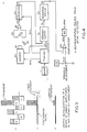
- FIG. 1 a pulsed metal detector of a simple type, as shown in FIG. 1.
- the power mains 1 are coupled into a multiplier 10 which supplies timing synchronization at an integer multiple (three, for example) of the power line frequency.
- Nearly rectangular current pulses are applied through driver 20 at this rate to the excitation coil 30.
- the signals induced in the receive coils 38 by decay of magnetism in object 35 are amplified at 40 and integrated at 50 to yield a series of samples at the output 59 of the integrator 50.
- Six such samples are displayed in FIG. 2A.
- the six samples, labeled (ABC) and (DEF) are acquired during two successive cycles of the AC power mains.
- These samples are passed through an analog bandpass filter 90 (FIG. 1) to remove unwanted frequency components.
- the remaining signal is compared at comparator 100 against a preset threshold 502. If the signal exceeds that threshold level, an alarm signal 109 is given.
- Two forms of interference signal which are always present in a walk-through metal detector are hum from the power mains, containing 60 Hz and its harmonics, and strong signals due to stationary metal in and around the detector coil array.
- FIG. 2 explains how these interferences are reduced.
- the interference components of each sample are shaded differently.
- the component due to hum is diagonally hatched.
- the component due to stationary metal is open and unshaded.
- the small potential signal due to a weapon is solid. Notice the relative magnitudes of these signals, which are typical for a metal detector.
- the signal processor needs to have a wide dynamic range capability in order to represent the signal.
- a weapon carried through a metal detector, will produce a slowly varying amount of signal. Passing the signal through a bandpass filter eliminates the rapid cyclic signal due to AC power, and the steady (DC) signal due to static metal. After bandpass filtering, the remaining signal is the weapon signal.
- a common means for addressing this problem is to pulse and observe at an odd-integer multiple (three, for example) of the power frequency, while inverting the excitation in coil 30 on alternate pulses.
- a representative series of samples, resulting from such an excitation pattern, is shown in FIG. 2B.
- the hum signals appear at the receiver input in the same sense as before, while the metal signals are alternately inverted.
- FIG. 2C shows the result when alternate samples are inverted within the receiver. Samples N,P, and R follow inverted stimulus pulses and have been inverted in the receiver. This double inversion is represented in FIG. 2C by a double hyphen(--).
- the metal signals always appear on the output in the same sense.
- any contribution due to hum is balanced three samples later by an equal and inverted sample.
- the hum component of M (FIG. 2C) is cancelled by the hum component of P, which is equal and inverted. Consequently, any sum of 6 x N adjacent samples, where N is any positive integer, contains the sum of all metal signals, but substantially no contribution due to steady hum.
- FIG. 4 shows an electronic system similar to the system of FIG. 1 which contains additional elements to accomplish the inversions described above.
- the timing system provides a control signal 13 which changes sign before each pulse. It controls the direction of the current provided by the driver 20.
- the signals induced in contraband object 35 now alternate in sign from sample to sample.
- the signals are picked up by the receive coils 38 and are processed as in FIG. 1 by amplifier 40 and integrator 50.
- the second signal inversion takes place in the receiver's demodulator 70 which inverts the integrator output signal under control of the same signal 13 that controls drive inversion.
- the signals 79 from the demodulator are represented in FIG. 2C.
- the summation process is approximated by using a lowpass filter at 90 (FIG.4) to average the samples.
- FOG.4 lowpass filter at 90
- a sampling process has aliased the hum signal to odd half-multiples of the power frequency, which are then blocked by lowpass filtering.
- the picture is different if the hum level changes abruptly.
- a transient may be present, as at sample E of FIG. 3A.
- This transient averaged into the 6N-sample ensemble, produces a signal output that can be large enough to cause an alarm.
- the word ensemble is used in this specification to refer to a selected number of signal samples, resulting from an unbroken series of signal observations.
- Phase-alternate sampling at three times the power frequency converts the receiver hum interference signal to half the power frequency. If the hum amplitude step is sufficiently large, sideband power, now centered at 30 Hz, can spill into the passband of the 10-Hz filter and cause an alarm. Such stepped power line transients are a major cause of external noise in metal detector installations.
- Stationary metal has three effects on a metal detector. It can introduce large offset levels at the input sampling integrator which tax the dynamic range of the metal detector. Second, it can distort the field pattern of the excitation or receive coils, causing variations in sensitivity as a function of the placement of the detector. Third, it can distort spatially uniform hum and interference fields into highly curved local patterns, in part defeating the built-in ability of most modern metal detector receiver coil arrays to ignore uniform fields.
- the dominant signal should be due to contraband metal carried through the detector.
- the bandpass filtered signal is compared against a threshold level. Excursions beyond that level are interpreted as contraband. Typically, an audible alarm is issued upon detection of such a threshold crossing.
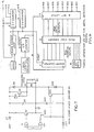
- FIG. 5 is a block diagram of the invention.
- the metal detector has a timing means 210.
- the timing means is synchronized to the operating frequency of the power mains 1 at an integer multiple of the power frequency.
- the timing means causes the driver means 20 to apply pulses of current to excitation coil 30 at the multiple frequency. These pulses have alternating direction.
- Signals from contraband object 35 responsive to changes in current at transmit coil 30 cause voltages to be induced in receive coils 38. These signals are amplified by 40 and passed on to a gated resettable integrator 250.
- the reset and integration timing are under control of logic signals 901-904 provided by the timing means 210, as described in more detail in FIG. 8.
- FIG. 9 shows the relative timing of signals from the timer of FIG. 8.
- Another signal 269 is input to the integrator from the static metal compensation circuit.
- Hum from the power mains is removed by a filtering means 260 as described in FIG. 11. Transients are limited by diodes 263 in FIG. 11. The reverses of signal direction due to reversals of the drive signal at coil 30 are removed in demodulator 270 of FIG. 12.
- the output of the demodulation circuit is filtered by components 291 through 295 of FIG. 13 and then applied to comparator and voting circuit 300 of FIG. 5, where a decision is made whether contraband metal is present. If it is present, an alarm 160 is activated.
- the demodulator output 79 is integrated by static metal integrator 310 of FIG. 5.
- the integrator output 319 of FIG. 13 is conditioned by an analog gated inverter 320 of FIG. 10.
- the resulting signal 269 is fed back to the input of integrator 250.
- the timing section 210 controls both the excitation timing signal 908 and the flow of data through the system.
- the timing plays an important supportive role in the invention.
- a schematic of one implementation of the timing section is shown in FIG. 8.
- the driver 20 of FIG. 5 is of conventional design.
- One example is shown in FIG. 7. It has a high voltage compliance and generates approximately rectangular current pulses having alternating current direction on each successive pulse. Pulses are separated by receiving intervals with no excitation.
- the input preamplifier 40 provides a controlled differential gain and bandwidth.
- Sampling integrator 250 is capable of positive or negative weighted integration. The exact timing of the integration is very important. The static-metal compensation is most easily implemented by applying a second input 269 to the integrator.
- a differential amplifier circuit capable of performing this task is shown in FIG. 10.
- Signal power at the integrator input 49 of FIG. 5 is dominated by two extraneous sources.
- the first which is called a static metal signal, is due to a leakage of excitation signals into the receive coils.
- Such leakage includes direct coupling from excitation to receive coils due to coil irregularities and indirect coupling through static metallic objects in regions where the transmit and receive coil fields overlap.
- a compensating signal provided by integrator 310 and gated inverter 320, is subtracted from the processed signal at the input of operational amplifier 251. The end effect is to remove the static metal signal from the output 59 of integrator 250.
- the second major interference, power-line hum, is substantially removed by a finite-impulse-response comb notch filter 260 titled "Hum and Transient Removal" in the schematic of FIG. 11.
- FIG. 3B Transients are exposed as signals which are much greater than metal signals and therefore may be limited by silicon diodes 263 (FIG. 11).
- FIG. 3C has a substantially reduced transient signal.
- the receiver inverts the samples marked "--" in FIG. 2C. In the inventive system, this inversion takes place in the demodulator 270 (FIG. 5). Such a demodulator is shown in detail in FIG. 12. A lowpass filter 290 of FIG. 13 reduces random noise somewhat. Then, the signal goes to a voting comparator 300 where the signal must be consistently beyond the alarm threshold for a certain number of time periods, regardless of amplitude, before an alarm is issued.
- All timing in the inventive system is derived from the timing circuit depicted in FIG. 8.
- the AC signal 1 from the power mains is coupled to the "reference frequency" input of a phase-locked-loop integrated circuit 2 such as a CD4046 made by RCA.
- the output 3 of the circuit drives a binary coded divide-by-seven counter 4, which may be a 74HC161 counter.
- the divided output 7 is fed back into the "controlled frequency” input of phase locked loop 2.
- the output frequency at 3 converges to a frequency which is equal to seven times the power mains frequency. This signal is used to synchronize the sequencing of all excitation and signal processing in the inventive system.
- the 7x-frequency (420 Hz in the USA or 350 Hz in Europe) is used to reset a digital counting cascade of divide-by-R counter 9 and a binary counter 15 every 1/420th second.
- Counter 9 is driven by a crystal oscillator 8 operating at approximately 14.3 MHz. Any other crystal frequency may be used so long as the division ratio R in programmable divider 9 is adjusted so as to produce the desired time base at the output 14.
- the binary counter 15 produces an output word which increments at 63.5 microsecond intervals.
- the output of this binary counting cascade is decoded in a programmable read-only memory 16.
- the output of the memory is latched by an 8-bit D-type digital latch 17.
- the timing pattern of the outputs 901-908 depends on a sampling program which is for a particular task. Up to thirty seven increments of 63.5 microseconds are available, each of which may be assigned as part of the cycle before a reset occurs. A new sampling sequence starts when the reset recurs. Several different timing patterns may be simultaneously stored in the memory and selected by means of program selection bits at 18.
- the 7x-frequency 3 is divided by two at divider 19 of FIG. 8, in order to produce an odd-even cyclic (sign) command signal to determine the polarity of the drive to the excitation coil 30.
- half of the pulses such as the even ones, energize the transmit coil 30 in one sense (e. g., positive), at a rate of 210 samples per second in the exemplary system.
- the intervening pulses, the odd ones in this example excite the space in the gate or portal in a negative sense.
- the response of the metal object 35 (FIG. 5) reverses sense to follow the excitation.
- Horizontal drive signals are radiated from closed circuit TV monitors and broadcast TV sets. They have in common, the horizontal retrace frequency is almost always the same in a given nation. The frequency is very tightly controlled by the electronics or camera originating the video image. In the USA the most common frequency is 15.750 KHz. Integration over an integer number of cycles of any AC signal will produce a null integral, regardless of the point in phase where the integration begins and ends, and regardless of the shape of the waveform. Because of these two facts, it is advantageous to set the interval between the incrementing of the timing address counter at exactly the standard horizontal retrace frequency which may be encountered by the system. As long as the integration periods implemented by the timing system incorporate an integer number of timing steps, the integration encompasses a precise integer number of horizontal retrace cycles.
- TV horizontal retrace signals are eliminated without requiring special filters, synchronization, or the like. It is also possible to set the time base to supply an integer multiple K of the interference frequency, and hold the integrator controls constant for an integer multiple of K counts to achieve the same effect.
- the time base may be changed in order to cancel other highly periodic and stable noise sources, including video displays employing other timing standards, switching power supplies, and very-low-frequency radio transmitters.
- the range of interference frequencies over which this technique can be conveniently and advantageously applied in pulsed metal detectors includes 2 KHz to 100 KHz.
- the integration interval should not deviate from an integer multiple of the interference signal period by more than 0.05 times the interference signal period. Rejection improves as one reduces this difference.
- the integration interval in the exemplary case is an integral multiple of 63.5 microseconds from divider 9 of FIG. 8.
- the horizontal retrace rate of 15.750 kHz has a period of 63.5 microseconds.
- the static signal 269 at the output of analog gated inverter 320 of FIG. 5, is returned to the input of the integrator 250.
- This signal is an estimate of the amount of metal signal which is to be expected due to furniture, floor reinforcements, etc. This estimate is arrived at by static metal integrator 310. As successive readings accumulate, the signal 269 slowly converges to a value such that, when the integration period of integrator 250 ends, the portion of the integral due to stationary metal is cancelled. Since the metal signal 49 presented to integrator 250 is inverted on alternate pulses, it is also necessary to invert the signal 269, if the signals are to cancel. This periodic inversion is accomplished by sign signal 13 in analog gated inverter 320.
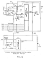
- Differential signals from receive coil 38 first pass through resistors 42, 43 (FIG. 10) and are shunted by capacitors 44, 45. These parts form a lowpass filter that removes signals due to radio transmissions and similar sources.
- Operational amplifier 41 must be a low noise high performance integrated circuit such as an OP 37 from Precision Monolithics. All other operational amplifier ICs (marked OA on drawings) in the system may be a medium-performance low-bias-current device such as the TL071 by Texas Instruments.
- the preamplifier gain is controlled by resistor 47 and the upper limit of frequency performance is controlled by capacitor 46.
- the output of the preamplifier 49 is inverted by amplifier 254, so that the signal and its inversion are available as inputs to the analog multiplexer.
- Operational amplifier 251 is connected with capacitor 258 to form an integrator.
- the input node "COM" of the integrator is supplied with current from several sources which may be selected by analog multiplexers 257 and 322, which may be a Siliconix DG508. These multiplexers are under control of the timing system via digital logic level signals 901-904, 13, and 319.
- the signal 904 enables both multiplexers 257 and 322.
- Signals 901, 902, and 903 together are a binary word for selecting whether the common point "COM" is connected to one of the resistors 252..256, or to the output 269, or to open-circuited inputs.
- the integrator Prior to acquisition of a sample, the integrator is reset by enabling a signal path between the terminals of capacitor 258, via multiplexer 257.
- the integrator When it is time to begin integration, the integrator is connected via 257 to one of four resistors 252, 253, 255, or 256. These resistors control the gain, or weighting, of the integration process. The smaller the resistor, the larger the weighting. Resistors 252 and 253, connected directly to the preamplifier, supply noninverted signals. These inputs have "positive" weight. The signals supplied via resistors 255 and 256 are derived from inverted signals; they have "negative” weight. Under control of signals 901..904 the weighting of the integration may be changed in less than a microsecond.
- the static metal signal from prior samples is expected to be unchanged for the next sample.
- This signal arrives at the integrator 251 via 269 from analog gated inverter 320 of FIG. 10.
- the expected static metal signal 319 is first inverted by operational amplifier 321 and the direct and inverted inputs presented as inputs to multiplexer 322, either of which may be selected by the state of control line 13. If line 904 is negated then none of the above inputs is enabled.
- the integrator 251 holds the value at 59, which was present when line 904 was negated. Following integration at 251, the value at 59 is held while processing continues.
- the next processing step is hum removal.
- An analog multiplexer 261 of FIG. 11, such as a DG508, connects the output of the integrator at 59 to the free end of one of seven capacitors in capacitor array 262. Each capacitor holds a voltage equal to the value at 59, which was taken seven cycles previously.
- the voltage at common connection 265 is the input to buffer 7. It is equal to the difference between the voltage currently presented at the integrator output 59 and the integrator output voltage presented by the integrator exactly one power line cycle (seven sample periods) earlier. If the hum pickup level is steady in phase and amplitude, then the hum component of the new sample will equal the prior component held in the appropriate capacitor of 262. The difference will be zero so that the steady hum component is cancelled. On the other hand, since the potential contraband metal signal is linearly proportional to the excitation current, and this has been reversed for the present sample relative to the one whose value was stored in the capacitor, that signal appears doubled in amplitude at point 265, and at buffered output 69.
- the signal amplitude is symmetrically limited by silicon signal diodes 263, such as 1N4148, as illustrated in FIG. 3B.
- Buffer amplifier output 69 is processed by demodulator 270 of FIG. 5.
- demodulator 270 of FIG. 5 Upon completion of the system cycle, a solid state transmission gate 264 of FIG. 11, which may be a Siliconix DG211, is enabled, grounding point 265. This stores the value at 59 until the next time this particular capacitor 262 is selected. The voltage thus stored will be subtracted from a new sample value at 59 seven observation cycles later, just as the value stored seven cycles prior to this one was subtracted from this value.
- This hum removal is closely related to a discrete-sampled comb-notch filter; however, the addition of transmission gate 264 (FIG. 11) at the filter output 265 yields a finite impulse response, i.e. a response which dies away very rapidly. This finite response helps isolate transient noise pulses and so minimize their effects.
- That signal which remains is due chiefly to metal passing through the detector, plus noise from small random sources, plus high and low level transients, as shown in FIG. 3B.
- the signal at input 265 of amplifier 7 (FIG. 11) represents only the difference of two samples of data, so limiting at this early point in the signal processing will corrupt only two data values.
- Limiting represented by crossed diodes 263, may also be obtained by other suitable electronic means, arranged to yield a response which is proportional to the input up to a certain level, and constant thereafter.
- the signal at point 265 of FIG. 11 then passes through a buffer amplifier 7 and is demodulated (FIG. 12).
- signal 69 is alternately steered via multiplexer 271, which may be a DG508, to holding capacitors 274 and 275 at the inputs of an operational amplifier 276 connected as a linear differential amplifier. Since the signals on capacitors 274 and 275 are amplified with equal gain, but in an opposite sense by amplifier 276, this steering synchronously demodulates the receiver signal, completing the process of double inversion which was begun by inverting the excitation signal.
- the next step is to save the integrator output voltage for the next power cycle. This process was mentioned above in the discussion of the hum filter.
- the demodulated signal 79 at the output of the differential amplifier is now lowpass filtered by operational amplifier circuit 295 of FIG. 13.
- the lowpass performance of the filter is determined by resistors 291, 292 and capacitors 293 and 294. Filtering at this point is necessary in order to improve the rejection of low-amplitude transients and random noise.
- an equivalent procedure is to take the sum of 14 or 28 successive samples (two or four cycles of the mains).
- the relatively clean signal from the lowpass filter is now ready for processing by the alarm sensing comparators (FIG. 13.)
- alarm comparators 302, 303 which may be parts such as LM339 by National Semiconductor.
- One comparator 302 is for positive voltage excursions and the other comparator 303 is for negative excursions.
- a low level at the output of either comparator represents the potential presence of a contraband object.
- the threshold reference voltage may be provided by manually adjusted potentiometer 502.
- An inverter 301 provides an equal negative threshold voltage, so that voltage excursions in either direction will result in an alarm condition.
- a simple lowpass filter following each comparator requires that the threshold crossing be consistent.
- Such a filter may be constructed of a resistor 304 and capacitor 305.
- Each independent time increment (approximately 30 milliseconds due to the lowpass filter 295) is allocated a single "vote” from comparator 302 or 303.
- the output of this comparator may be high or low ("nay” or “yea” respectively) on the question of issuing an alarm. This output does not depend on the degree to which the threshold has been exceeded at the inputs of the comparators (in the case of a "yea” vote).
- the values of filter 304, 305, or filter 306, 307 which determine the time constants of the post comparison filters may be adjusted to include more or fewer votes in the election (two out of four or eight out of sixteen, for example).
- the threshold "majority”, the number of "yea” votes required to issue an alarm may be adjusted by adding a bias current at the comparator outputs. A setting that yields two out of four votes appears to be about right. The majority is sensed at either input of logic gate 308, which may be a CD 4093 by RCA.
- the "alarm" output 109 of NOR gate 308 may be applied to any suitable annunciator or actuator, or may be used to disable an access mechanism.
- the static metal signal mentioned above must be generated dynamically. Changes due to thermal drift, aging, rearrangement of furniture and similar effects change the metal signal. These changes can be much larger than the signal from a small contraband object, and thus can cause false alarms.
- the metal signal is amplified by operational amplifier 311 of FIG. 13 and applied through a transmission gate 312 to an integrator comprising resistor 313, capacitor 314, and amplifier 315.
- the product of resistance 313 and capacitance 314 is on the order of a minute, so the rate of change of the integrator's output voltage is very slow. If it reacted too quickly, signals from slowly moving objects would be nullified by inclusion of their signals in the static metal signal. If this happened, the object would not be detected. In spite of the slow rate of integration, an equilibrium state will eventually be attained for signals from objects that are truly stationary. Equilibrium occurs when enough static metal compensation is developed that the voltage at the input of amplifier 311 averages to zero.
- Metal detectors must frequently be used in conjunction with heavy metal doors in security areas. Because the doors are so massive, they may result in a changing metal signal that triggers false alarms, even though the doors do not open into the volume where the detector is most sensitive. The most straight forward approach, if feasible, is to move the metal detector further from the door. If this is not possible, the door may be made of some non-conductive material, such as glass, wood, or plastic.
- the invention accommodates moving doors another way.
- the position of the door 31 is monitored by a transducer 32, connected to the hinge of the door.
- a table is created in the memory of the control processor, defining changes in the metal signal as a function of door position.
- the metal signal corresponding to the door at that position is subtracted from the measured signal.
- the signal from a nearby metal door is cancelled at each position of the door.
- the door does not interfere with the detector.
- There are many ways to measure a door's position One means uses a digital encoder attached to the door's hinge. Another employs an analog potentiometer attached to the hinge, followed by an analog to digital converter 230.
- the position sensor 32 need not be linear, but it must be monotonic (steadily increase as the door is opened) and repeatable.
- Cancelling signals from a moving metal object for example a door, proceeds as follows:
- a transmission gate 312 (FIG. 13) is included between the amplifier 311 and the static metal integrator at 315.
- the decision concerning when to disable the integrator is made by some external device, such as a switch, keyed to the event.
- the integration may be stopped by asserting line 33, SMI INHIBIT. This inhibits integration via transmission gate 312.
- the integral stored in capacitor 314 will be held for a time limited only by the internal leakage of the integrator circuit.
- Component value drift or noncatastrophic failure may alter the sensitivity of the metal detector without necessarily causing immediately observable symptoms. Such changes must be promptly detected, since failure to do so could have expensive or perhaps even deadly consequences. There is no substitute for human vigilance, but the invention incorporates an important backup device. With this device, most sensitivity changes will be promptly detected.
- FIG. 14 depicts the test fixture, having a self-test coil 120, with 200 tightly bundled turns of 28 Gauge wire on a 10 Cm diameter coil.
- This coil is attached to a switch such as a power MOSFET 121 such as IRF610 by Motorola.
- a switch such as a power MOSFET 121 such as IRF610 by Motorola.
- the MOSFET When the MOSFET is biased into a low-resistance state, the coil, having been shorted by the MOSFET, will behave magnetically about the same as a copper ring of the same diameter, weight, and placement. It will induce strong signals in receive coils if it is nested into one side of the receiver coil array 38, as shown in FIG. 10.
- the metal detector can calibrate its entire signal path, from excitation driver 20 of FIG. 5, through coil integrity (30, 38), through cable attachments, preamplifier 40, and all the way through to the alarm. If the difference at this point is too large or too small, as compared to preset limits, the system may warn the user of a malfunction. In the case of a microprocessor implementation, this is a matter of writing a software subprogram, stored in the microprocessor's digital memory 232 of FIG. 6, to execute the test, evaluate the results and issue appropriate signals.
- a hand-held sensitivity probe may also be used.
- the MOSFET switch is driven with a 1 Hz square wave from a digital multivibrator.
- a special integration protocol at integrator 250 of FIG. 5 and 6 permits detection of small steel firearms without false-alarming on typical pocket clutter.
- a very simple integration beginning at the instant when the field starts to collapse and ideally extending to infinity, will yield a null result for an ohmically conductive object.
- the integral will not be zero if the object has high magnetic permeability or is superconductive.
- the conductivity will be ignored and only the permeability will be sensed.
- permeable will be used to mean that an object is able to pass low level magnetic flux at least 20% more easily than empty space. Examples of permeable materials are iron, most steels, magnetic ferrites, and certain rare earth metals. Copper, brass, aluminum, gold, living matter, magnetic recording media, and fabric are not permeable materials for our purposes.
- coil 30 is driven at constant current by a driver 20 with high voltage compliance.
- Driver coil 30 and receive coil 38 are constructed to minimize mutual coupling between the coils.
- a change of current in coil 30 will then induce a minimal voltage transient in 38.
- the total absence of mutual coupling is not necessary for successful operation, but the coupling must be small enough so that the preamplifier 40 and the integrator 250 can accommodate the entire signal amplitude induced in the receive coils 38, without distortion.
- the coupling between the coils is modulated by the presence of a conductive or magnetically permeable object 35, such as a pistol, that distorts the field of coil 30, either temporarily or permanently. If such an object is present, then a change of current in coil 30 will induce a transient voltage in coil 38.
- the signal from coil 38 may be used to indicate the presence of the object.
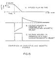
- the method of processing the signal is such that only permeability is detected, to the exclusion of conductive "eddy current" responses.
- the collapse of the field of transmit coil 30 is locally amplified by the collapse of the induced magnetization of object 35.
- the result (FIG. 15C) is a unipolar pulse in receive coil 38 which is proportional to the size and permeability of object 35.
- the time integral of this response is distinctly nonzero. It so happens that all metals presently used for making gun barrels, including stainless steel guns, are magnetically permeable, so this property of permeability is a good indicator of the presence of a gun.
- the time integral of voltage induced in coil 38 is proportional to the net flux change in the coil.
- the change in the integral due to the presence of an object, is proportional to the change in the net flux in the coil, due to the presence of the object.
- a conductive object such as aluminum or silver, having a permeability that matches free space, does not affect the field either before or long after the collapse of the field from coil 30.
- the time integral of voltage induced by this object will be zero, regardless of the detailed shape, magnitude or time constant of the response.
- a permeable object or superconductor will distort the static applied field prior to the collapse, and in particular distort it differently following the collapse, the above integral will not be zero. It may be used as an indicator of the presence of a magnetically permeable object.
- Small steel objects such as a North American Arms .22 Cal stainless steel minirevolver are detected by the above protocol, while large nonmagnetic conductive objects such as aluminum drink cans or decorative silver belt buckles are ignored.
- Suitable encoding of Read Only Memory 16 of FIG. 8 can provide timing control of amplifier 41 outputs through resistors 252, 253, 255 and 256 of FIG. 10 to achieve the discrimination previously described.
- the timing control appears as 901, 902 and 903 of FIG. 10.
Landscapes
- Life Sciences & Earth Sciences (AREA)
- Engineering & Computer Science (AREA)
- Physics & Mathematics (AREA)
- Geophysics (AREA)
- General Life Sciences & Earth Sciences (AREA)
- General Physics & Mathematics (AREA)
- Remote Sensing (AREA)
- Manufacturing & Machinery (AREA)
- Electromagnetism (AREA)
- Environmental & Geological Engineering (AREA)
- Geology (AREA)
- Geophysics And Detection Of Objects (AREA)
- Testing Electric Properties And Detecting Electric Faults (AREA)
Applications Claiming Priority (2)
| Application Number | Priority Date | Filing Date | Title |
|---|---|---|---|
| US141706 | 1988-01-07 | ||
| US07/141,706 US4821023A (en) | 1988-01-07 | 1988-01-07 | Walk-through metal detector |
Publications (2)
| Publication Number | Publication Date |
|---|---|
| EP0323713A2 true EP0323713A2 (de) | 1989-07-12 |
| EP0323713A3 EP0323713A3 (de) | 1990-11-14 |
Family
ID=22496859
Family Applications (1)
| Application Number | Title | Priority Date | Filing Date |
|---|---|---|---|
| EP19880311508 Withdrawn EP0323713A3 (de) | 1988-01-07 | 1988-12-05 | Begehbarer Metalldetektor |
Country Status (3)
| Country | Link |
|---|---|
| US (1) | US4821023A (de) |
| EP (1) | EP0323713A3 (de) |
| CA (1) | CA1306033C (de) |
Cited By (1)
| Publication number | Priority date | Publication date | Assignee | Title |
|---|---|---|---|---|
| EP0733915A3 (de) * | 1995-03-23 | 1997-09-03 | Vallon Gmbh | Verfahren und Messeinrichtung zur Metalldetektion mittels einer Spulenanordnung mit mehreren separat ansteuerbaren Bereichen |
Families Citing this family (62)
| Publication number | Priority date | Publication date | Assignee | Title |
|---|---|---|---|---|
| GB8920412D0 (en) * | 1989-09-08 | 1989-10-25 | Ca Atomic Energy Ltd | Metal detecting system |
| US5083111A (en) * | 1990-11-26 | 1992-01-21 | Sensormatic Electronics Corporation | Jamming apparatus for electronic article surveillance systems |
| US5493517A (en) * | 1991-06-03 | 1996-02-20 | Hughes Missile Systems Company | Cargo container mapping system |
| US5414411A (en) * | 1993-06-21 | 1995-05-09 | White's Electronics, Inc. | Pulse induction metal detector |
| US5576621A (en) * | 1994-03-10 | 1996-11-19 | Denver Dynamics, Inc. | Hinged metal detection cover for a receptacle |
| DE69615435T2 (de) * | 1995-03-31 | 2002-05-16 | New Holland Belgium N.V., Zedelgem | Kompensation für Starttransienten |
| US5600942A (en) * | 1995-03-31 | 1997-02-11 | New Holland North America, Inc. | Adaptive thresholding for metal detection |
| US5790685A (en) * | 1995-06-29 | 1998-08-04 | Tracor, Inc. | Apparatus and method for detecting and imaging metal |
| US5726628A (en) * | 1996-05-06 | 1998-03-10 | Gd Electronics, Inc. | Metal detector system |
| FR2765420B1 (fr) * | 1997-06-26 | 1999-10-01 | Canon Kk | Procede et dispositif pour detecter un evenement susceptible d'affecter la transmission d'un signal |
| US6438500B1 (en) | 1997-06-26 | 2002-08-20 | Canon Kabushiki Kaisha | Method and device for detecting the absence of a product in a reservoir |
| US6574031B1 (en) * | 1997-12-08 | 2003-06-03 | The United States Of America As Represented By The Administrator Of The National Aeronautics And Space Administration | Method for balancing detector output to a desired level of balance at a frequency |
| KR100228251B1 (ko) * | 1997-12-20 | 1999-11-01 | 박병용 | 권총류 탐지시스템 |
| ITTO980146A1 (it) * | 1998-02-25 | 1999-08-25 | Alessandro Manneschi | Sistema rivelatore per controllo di accesso e relativo gruppo rivela- tore. |
| US6133829A (en) * | 1999-03-05 | 2000-10-17 | Frl, Inc. | Walk-through metal detector system and method |
| US6362739B1 (en) | 1999-09-22 | 2002-03-26 | Garry L. Burton | Passive security device for detecting ferromagnetic objects |
| FR2806808B1 (fr) * | 2000-03-24 | 2002-05-24 | Ela Medical Sa | Circuit de detection de la presence d'un aimant permanent au voisinage d'un dispositif medical actif, notamment d'un stimulateur cardiaque, defibrillateur, cardioverteur et/ou dispositif multisite |
| US7671744B2 (en) * | 2003-03-03 | 2010-03-02 | Veroscan, Inc. | Interrogator and interrogation system employing the same |
| US7411506B2 (en) * | 2003-03-03 | 2008-08-12 | Veroscan, Inc. | Interrogator and interrogation system employing the same |
| US7764178B2 (en) * | 2003-03-03 | 2010-07-27 | Veroscan, Inc. | Interrogator and interrogation system employing the same |
| US8063760B2 (en) * | 2003-03-03 | 2011-11-22 | Veroscan, Inc. | Interrogator and interrogation system employing the same |
| US7541933B2 (en) * | 2003-03-03 | 2009-06-02 | Veroscan, Inc. | Interrogator and interrogation system employing the same |
| US8542717B2 (en) | 2003-03-03 | 2013-09-24 | Veroscan, Inc. | Interrogator and interrogation system employing the same |
| US7019650B2 (en) * | 2003-03-03 | 2006-03-28 | Caducys, L.L.C. | Interrogator and interrogation system employing the same |
| US7893840B2 (en) * | 2003-03-03 | 2011-02-22 | Veroscan, Inc. | Interrogator and interrogation system employing the same |
| US8174366B2 (en) * | 2003-03-03 | 2012-05-08 | Veroscan, Inc. | Interrogator and interrogation system employing the same |
| JP2006525512A (ja) * | 2003-04-29 | 2006-11-09 | フィッシャー リサーチ ラボラトリー | 可搬ウォークスルー金属検出器用のシステムおよび方法 |
| US7145456B2 (en) * | 2003-04-29 | 2006-12-05 | Fisher Research Labs, Inc. | Efficient electronics for a walk-through metal detector |
| EP1738295A1 (de) | 2004-03-03 | 2007-01-03 | Caducys L.L.C. | Interrogator und interrogationssystem damit |
| US20060017545A1 (en) * | 2004-03-26 | 2006-01-26 | Volpi John P | Radio frequency identification interrogation systems and methods of operating the same |
| US7501948B2 (en) * | 2004-09-29 | 2009-03-10 | Lone Star Ip Holdings, Lp | Interrogation system employing prior knowledge about an object to discern an identity thereof |
| GB2423366B (en) | 2005-02-16 | 2010-02-24 | Cintex Ltd | Metal detector |
| GB0808344D0 (en) * | 2008-05-08 | 2008-06-18 | Owlstone Ltd | Sensor |
| US20070035383A1 (en) * | 2005-08-09 | 2007-02-15 | Roemerman Steven D | Radio frequency identification interrogation systems and methods of operating the same |
| US20080017790A1 (en) * | 2006-07-20 | 2008-01-24 | Owlstone Nanotech Inc. | Smart FAIMS sensor |
| US7714277B2 (en) * | 2006-07-20 | 2010-05-11 | Owlstone Nanotech, Inc. | Smart FAIMS sensor |
| WO2008094299A2 (en) * | 2006-07-20 | 2008-08-07 | Owlstone Nanotech, Inc. | Smart faims sensor |
| US7796733B2 (en) * | 2007-02-01 | 2010-09-14 | Rapiscan Systems, Inc. | Personnel security screening system with enhanced privacy |
| US8638904B2 (en) | 2010-03-14 | 2014-01-28 | Rapiscan Systems, Inc. | Personnel screening system |
| US8576982B2 (en) | 2008-02-01 | 2013-11-05 | Rapiscan Systems, Inc. | Personnel screening system |
| US8995619B2 (en) | 2010-03-14 | 2015-03-31 | Rapiscan Systems, Inc. | Personnel screening system |
| CN103064125B (zh) * | 2007-06-21 | 2016-01-20 | 瑞皮斯坎系统股份有限公司 | 用于提高受指引的人员筛查的系统和方法 |
| US7755491B2 (en) * | 2007-08-13 | 2010-07-13 | Veroscan, Inc. | Interrogator and interrogation system employing the same |
| JP4539699B2 (ja) * | 2007-09-19 | 2010-09-08 | 富士ゼロックス株式会社 | 携行物管理ゲート |
| US8003949B2 (en) | 2007-11-01 | 2011-08-23 | Rapiscan Systems, Inc. | Multiple screen detection systems |
| CA2710655C (en) * | 2007-12-25 | 2018-06-12 | Rapiscan Systems, Inc. | Improved security system for screening people |
| US8704638B2 (en) * | 2008-07-07 | 2014-04-22 | Tyco Fire & Security Services GmbH | Electronic article surveillance system with metal detection capability and method therefor |
| GB0905298D0 (en) | 2009-03-27 | 2009-05-13 | Qinetiq Ltd | Apparatus and method for ferromagnetic object detector |
| WO2011063059A1 (en) * | 2009-11-18 | 2011-05-26 | Rapiscan Systems, Inc. | X-ray based system and methods for inspecting a person's shoes for aviation security threats |
| GB2494963B (en) | 2010-03-14 | 2017-02-22 | Rapiscan Systems Inc | Multiple screen detection systems |
| WO2012027783A1 (en) * | 2010-08-29 | 2012-03-08 | Goldwing Design & Construction Pty Ltd | Method and apparatus for a metal detection system |
| US9035774B2 (en) | 2011-04-11 | 2015-05-19 | Lone Star Ip Holdings, Lp | Interrogator and system employing the same |
| US11280898B2 (en) | 2014-03-07 | 2022-03-22 | Rapiscan Systems, Inc. | Radar-based baggage and parcel inspection systems |
| KR20160130482A (ko) | 2014-03-07 | 2016-11-11 | 라피스캔 시스템스, 인코포레이티드 | 초광대역 검출기 |
| AU2015353439A1 (en) | 2014-11-25 | 2017-06-29 | Rapiscan Systems, Inc. | Intelligent security management system |
| CN108028648B (zh) * | 2015-09-11 | 2021-06-11 | 巴鲁夫股份有限公司 | 用于检测目标物体的传感器设备和用于运行用于检测目标物体的传感器设备的方法 |
| PL3491629T3 (pl) * | 2016-07-26 | 2020-12-28 | Alert Systems Aps | Sposób, aparat i system do wykrywania metalowych obiektów w strefie detekcji |
| EP3520120A4 (de) | 2016-09-30 | 2020-07-08 | American Science & Engineering, Inc. | Röntgenstrahlenquelle zur zweidimensionalen abtaststrahlbildgebung |
| RU2647991C1 (ru) * | 2016-11-18 | 2018-03-21 | Общество с ограниченной ответственностью "Локаторная техника" | Металлообнаружитель |
| CN106842336A (zh) * | 2017-02-09 | 2017-06-13 | 王积东 | 通过式探测器及通过式探测方法 |
| FR3083329B1 (fr) * | 2018-06-28 | 2021-06-18 | Alessandro Manneschi | Systeme de detection portable comprenant des capteurs magnetostatiques |
| JP6833096B1 (ja) * | 2020-10-08 | 2021-02-24 | 株式会社沖縄計測 | 磁気探査装置、磁気探査方法、および磁気探査プログラム |
Family Cites Families (14)
| Publication number | Priority date | Publication date | Assignee | Title |
|---|---|---|---|---|
| US2179240A (en) * | 1937-01-02 | 1939-11-07 | Illinois Testing Laboratories | Metal detection device |
| US3697972A (en) * | 1969-06-26 | 1972-10-10 | Yull Brown | Metal detection and alarm systems |
| US3697996A (en) * | 1969-07-11 | 1972-10-10 | Minnesota Mining & Mfg | Electromagnetic field producing apparatus and method for sequentially producing a plurality of fields |
| US3676772A (en) * | 1970-08-18 | 1972-07-11 | Nasa | Metallic intrusion detector system |
| US3686564A (en) * | 1970-10-08 | 1972-08-22 | Westinghouse Electric Corp | Multiple frequency magnetic field technique for differentiating between classes of metal objects |
| US3763424A (en) * | 1971-07-15 | 1973-10-02 | Sperry Rand Corp | Metal detector for identifying and discriminating between objects of different size, shape, orientation and ferrous content and including an auto nulling circuit |
| US3889249A (en) * | 1971-10-29 | 1975-06-10 | Sperry Rand Corp | Static magnetic field metal detector |
| US3758849A (en) * | 1972-03-31 | 1973-09-11 | Sperry Rand Corp | Metal detector system having identical balanced field coil system on opposite sides of a detection zone |
| US3971983A (en) * | 1972-06-06 | 1976-07-27 | Infinetics, Inc. | Ferromagnetic metal detector utilizing gradiometers positioned on opposite sides of the detection area with overlapping sensitivity |
| US4012690A (en) * | 1974-01-22 | 1977-03-15 | Solomon Heytow | Device for selectively detecting different kinds and sizes of metals |
| US3950696A (en) * | 1974-04-29 | 1976-04-13 | Westinghouse Electric Corporation | Trapezoidal coil configuration for metal detector in the shape of an inverted u |
| BE871580A (fr) * | 1978-10-26 | 1979-02-15 | Janssen Lambert | Systeme electromagnetique de detection |
| US4309697A (en) * | 1980-10-02 | 1982-01-05 | Sensormatic Electronics Corporation | Magnetic surveillance system with odd-even harmonic and phase discrimination |
| FR2492539A1 (fr) * | 1980-10-20 | 1982-04-23 | Morey Gilles | Procede et systeme de detection notamment pour installations de surveillance ou automatismes |
-
1988
- 1988-01-07 US US07/141,706 patent/US4821023A/en not_active Expired - Fee Related
- 1988-12-05 EP EP19880311508 patent/EP0323713A3/de not_active Withdrawn
- 1988-12-09 CA CA000585531A patent/CA1306033C/en not_active Expired - Lifetime
Cited By (2)
| Publication number | Priority date | Publication date | Assignee | Title |
|---|---|---|---|---|
| EP0733915A3 (de) * | 1995-03-23 | 1997-09-03 | Vallon Gmbh | Verfahren und Messeinrichtung zur Metalldetektion mittels einer Spulenanordnung mit mehreren separat ansteuerbaren Bereichen |
| US5859532A (en) * | 1995-03-23 | 1999-01-12 | Vallon Gmbh | Method of and measuring arrangement for metal detection with a coil device having several separately controllable regions |
Also Published As
| Publication number | Publication date |
|---|---|
| EP0323713A3 (de) | 1990-11-14 |
| CA1306033C (en) | 1992-08-04 |
| US4821023A (en) | 1989-04-11 |
Similar Documents
| Publication | Publication Date | Title |
|---|---|---|
| US4821023A (en) | Walk-through metal detector | |
| CA2179993C (en) | Metal detection system | |
| US4544892A (en) | Signal processing apparatus for frequency domain geophysical electromagnetic surveying system | |
| US6150810A (en) | Method for detecting the presence of a ferromagnetic object using maximum and minimum magnetic field data | |
| US5576624A (en) | Pulse induction time domain metal detector | |
| MXPA96002831A (es) | Sistema para deteccion de metales | |
| AU2007291894B2 (en) | Method and apparatus for signal recovery | |
| US4206451A (en) | Intrusion detection system | |
| AU751622B2 (en) | Metal detector method and apparatus | |
| US5654637A (en) | Method for detecting buried high conductivity objects including scaling of voltages for eliminating noise of a particular depth | |
| US20190353818A1 (en) | Metal detector | |
| AU8082791A (en) | Sub-audio magnetics instrument | |
| AU2005301093B2 (en) | Metal detector | |
| US5047718A (en) | Improving the discrimination of an impulse technique metal detector by correlating responses inside and outside of a cut-off peak area | |
| US4635207A (en) | Field measuring system | |
| Panaitov et al. | Peculiarities of SQUID magnetometer application in TEM | |
| Varotsos et al. | Magnetic field variations associated with SES The instrumentation used for investigating their detectability | |
| RU2210116C2 (ru) | Сейсмомагнитометрическое устройство для охранной сигнализации | |
| WO1997050000A2 (en) | Advanced metal detection equipment using fluxgate magnetometers | |
| AU782741B2 (en) | Metal detector method and apparatus | |
| JPS641388B2 (de) | ||
| Svatos | Metal discrimination using time domain processed SINC signal | |
| SU949599A1 (ru) | Устройство дл обнаружени металлических частиц в потоке сырь | |
| CA2149828C (en) | Method of detecting buried high conductivity objects | |
| CS239550B1 (cs) | Zařízení pro magnetotelurické sondování |
Legal Events
| Date | Code | Title | Description |
|---|---|---|---|
| PUAI | Public reference made under article 153(3) epc to a published international application that has entered the european phase |
Free format text: ORIGINAL CODE: 0009012 |
|
| AK | Designated contracting states |
Kind code of ref document: A2 Designated state(s): DE ES FR GB IT NL SE |
|
| PUAL | Search report despatched |
Free format text: ORIGINAL CODE: 0009013 |
|
| AK | Designated contracting states |
Kind code of ref document: A3 Designated state(s): DE ES FR GB IT NL SE |
|
| RAP1 | Party data changed (applicant data changed or rights of an application transferred) |
Owner name: EG & G ASTROPHYSICS RESEARCH CORPORATION |
|
| 17P | Request for examination filed |
Effective date: 19910507 |
|
| 17Q | First examination report despatched |
Effective date: 19920514 |
|
| STAA | Information on the status of an ep patent application or granted ep patent |
Free format text: STATUS: THE APPLICATION IS DEEMED TO BE WITHDRAWN |
|
| 18D | Application deemed to be withdrawn |
Effective date: 19921110 |