EP0323598B1 - Apparatus for scaling teeth and lavage - Google Patents
Apparatus for scaling teeth and lavage Download PDFInfo
- Publication number
- EP0323598B1 EP0323598B1 EP88121158A EP88121158A EP0323598B1 EP 0323598 B1 EP0323598 B1 EP 0323598B1 EP 88121158 A EP88121158 A EP 88121158A EP 88121158 A EP88121158 A EP 88121158A EP 0323598 B1 EP0323598 B1 EP 0323598B1
- Authority
- EP
- European Patent Office
- Prior art keywords
- insert
- scaling
- tip
- handpiece
- fluid
- Prior art date
- Legal status (The legal status is an assumption and is not a legal conclusion. Google has not performed a legal analysis and makes no representation as to the accuracy of the status listed.)
- Expired - Lifetime
Links
Images


Classifications
-
- A—HUMAN NECESSITIES
- A61—MEDICAL OR VETERINARY SCIENCE; HYGIENE
- A61C—DENTISTRY; APPARATUS OR METHODS FOR ORAL OR DENTAL HYGIENE
- A61C1/00—Dental machines for boring or cutting ; General features of dental machines or apparatus, e.g. hand-piece design
- A61C1/0061—Air and water supply systems; Valves specially adapted therefor
- A61C1/0084—Supply units, e.g. reservoir arrangements, specially adapted pumps
-
- A—HUMAN NECESSITIES
- A61—MEDICAL OR VETERINARY SCIENCE; HYGIENE
- A61C—DENTISTRY; APPARATUS OR METHODS FOR ORAL OR DENTAL HYGIENE
- A61C17/00—Devices for cleaning, polishing, rinsing or drying teeth, teeth cavities or prostheses; Saliva removers; Dental appliances for receiving spittle
- A61C17/16—Power-driven cleaning or polishing devices
- A61C17/20—Power-driven cleaning or polishing devices using ultrasonics
-
- B—PERFORMING OPERATIONS; TRANSPORTING
- B23—MACHINE TOOLS; METAL-WORKING NOT OTHERWISE PROVIDED FOR
- B23Q—DETAILS, COMPONENTS, OR ACCESSORIES FOR MACHINE TOOLS, e.g. ARRANGEMENTS FOR COPYING OR CONTROLLING; MACHINE TOOLS IN GENERAL CHARACTERISED BY THE CONSTRUCTION OF PARTICULAR DETAILS OR COMPONENTS; COMBINATIONS OR ASSOCIATIONS OF METAL-WORKING MACHINES, NOT DIRECTED TO A PARTICULAR RESULT
- B23Q1/00—Members which are comprised in the general build-up of a form of machine, particularly relatively large fixed members
- B23Q1/0009—Energy-transferring means or control lines for movable machine parts; Control panels or boxes; Control parts
- B23Q1/0018—Energy-transferring means or control lines for movable machine parts; Control panels or boxes; Control parts comprising hydraulic means
- B23Q1/0027—Energy-transferring means or control lines for movable machine parts; Control panels or boxes; Control parts comprising hydraulic means between moving parts between which an uninterrupted energy-transfer connection is maintained
- B23Q1/0036—Energy-transferring means or control lines for movable machine parts; Control panels or boxes; Control parts comprising hydraulic means between moving parts between which an uninterrupted energy-transfer connection is maintained one of those parts being a tool
Definitions
- the present invention relates to an insert for use in an apparatus for scaling of teeth, and for lavage of the gingival sulcus and other parts of the mouth requiring lavage.
- the apparatus is capable of providing scaling alone, lavage alone, or for providing both simultaneously.
- most prior art scaling devices have a conduit that transports tap water to the handpiece and onto the scaling tip for cooling thereof.
- the tap water is first used to circulate around the tranducer stack to cool the stack, and is then dispensed onto the scaling tip to cool the tip.
- the cooling water is directed to the scaling tip only. The cooling water is thereafter dispensed into the patient's mouth during the scaling procedure to cleanse the operating field of debris.
- the insert for use in an apparatus used for scaling teeth and for therapeutic lavage.
- the insert comprises a scaling tip, retaining means for retaining the scaling tip in the insert and a path means for delivering irrigant for scaling or for lavage through the insert to the end of the scaling tip.
- the path means comprises an inlet for permitting flow of fluid into the retaining means and a bore through the scaling tip communicating with the inlet.
- a channel on the outside of the scaling tip directs fluid from the retaining means to the distal end of the scaling tip.
- the insert is used for ultrasonic scaling, and the insert comprises as a part thereof a magnetostrictive stack
- the insert has an outlet for removing stack cooling water from around the stack so that the stack cooling water is not dispensed into the mouth of a patient.
- the scaling tip is shaped and dimensioned for scaling and lavage below the gumline in periodontal pockets. Inserts having specific shapes for use in deep periodontal pockets, and left and right bends for access for scaling between and under the roots of molars are also provided.
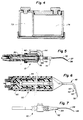
- FIG. 1 is a perspective view of the apparatus of the invention including the base unit, foot switch and handpiece.
- FIG. 2 is a schematic illustration of the apparatus of the invention.
- FIG. 3 is a cutaway top view of the base unit of the invention illustrating an alternative embodiment of the reservoir configuration.
- FIG. 4 is a cutaway side view along line 4-4 illustrating an alternative embodiment of the reservoir configuration of FIG. 3.
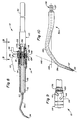
- FIG. 5 is a cutaway view of a handpiece of the invention with a hollow tip and external flow return.
- FIG. 6 is a alternative ultrasonic scaling, periodontal lavage handpiece.
- FIG. 7 is an alternative embodiment of a handpiece with means separate from the tip for spraying and cooling the tip.
- FIG. 8 is an embodiment of the insert of the invention which uses end delivery of irrigant.
- FIG. 9 is section 9-9 of FIG 8 rotated 90°.
- FIG. 10 illustrates a preferred shape of a scaling/lavage tip with a double bend.
- FIG. 11 is an embodiment of an insert which has a tip design adapted to direct irrigant on the outside of the scaling tip.
- FIG. 12 is an end view along line 12-12 of the embodiment of FIG. 11.
- FIG. 13 illustrates a second preferred shape of a scaling/lavage tip with a gooseneck.
- FIG. 14 illustrates a scaling tip for right molar root planing.
- FIG. 15 is an end view along line 15-15 of the embodiment of FIG. 14.
- the apparatus of the invention comprises a base unit 10, a handpiece 12 comprising handle 13 and insert 14 and foot switch 27.
- a conduit 15 connects the handpiece 12 to the base unit 10.
- conduit 15 is connected to outlets 40 and 42 of separate cylindrical reservoirs 36 and 38, respectively, in base unit 10.
- Reservoirs 36 and 38 are provided to store one or more medicament fluids that can be transported from the reservoirs to be dispensed through handpiece 12 and insert 14 when desired. Fluid can be introduced into reservoirs 36 and 38 through a refill opening therein which are closed by caps 16 and 18 respectively.
- handle 13 has means therein which is adapted to impart a vibration to insert 14.
- Such means are well known in the art and may be mechanical, magnetostrictive or piezoelectric in nature.
- tip 32 of insert 14 is touched lightly against a tooth by the practitioner, tip 32 is capable, because of its vibratory movement, of removing plaque and calculus from the tooth.
- scaling tips adapted to vibrate anywhere from 6 to 50 KHZ may be used for scaling of teeth.
- power control 26 may be used to vary the power of handle 13. Frequencies above about 20 KHZ are generally considered to be in the ultrasonic range.
- the apparatus of the invention may be used as a conventional ultrasonic scaler, in which case switch 24 will be set to a first position (condition 1) so that no medicaments are delivered from reservoirs 36 and 38, and ordinary tap water is used to cool the scaling tip and to irrigate the mouth during ultrasonic scaling.
- Conventional ultrasonic inserts of the magnetostrictive type have a flow through passage that utilizes the water used to cool the tranducer stack to also cool the scaling tip.
- the flow of the cooling water is conventionally set at about 35 cc/min and can be further controlled using flow control knob 25, and flow of cooling water to the handpiece is activated by setting foot control 27 to its second position.
- solenoid valve 68 When foot control 27 is in the second position, solenoid valve 68 is activated permitting the flow of water through regulator 70, through solenoid 68 to handpiece 12 and over the scaling tip. When foot switch 27 is pushed to its second position, vibration of insert 14 is also initiated.
- Vibration module 11 supplies the vibrating frequency to the handpiece by generating an ocillating electric current.
- the frequency of the electric current generated by vibration module 11 is directly related to the frequency at which the insert vibrates.
- condition 2 When switch 24 is set to a second position (condition 2) the apparatus is adapted for lavage by activating solenoids 56 and 58 which are put into operation by depressing one or both of buttons 20 and 22 and moving foot control 27 to its first position.
- air pressure from air supply 60 is reduced by regulator 66 forcing fluid from either reservoir 36 or 38 or both into conduit 15, through inlet 44 to insert 14 and through scaling tip 32 to be dispensed in the mouth.
- the air pressure will be controlled by regulator 66, and the air supply will be maintained adjustably by control knob 28 at about 2 - 16 psi.
- the air supply line will be equipped with at least one filter 62, an inlet solenoid valve 64 and a regulator 66.
- reservoirs 36 and 38, or the lines leading therefrom can be equipped with pump means for dispensing fluid from reservoirs 36 and 38.
- the lines leading from reservoirs 36 and 38 be equipped with check valves 61 and 71 which are used to insure that flow in the line is only in one direction. This prevents, for example, the flow of fluid from reservoir 38 to reservoir 36 when dispensing fluid from only reservoir 38. Vibration in insert 14 is initiated when footswitch 27 is moved to its second position.
- flow control 28 is used to control the flow rate of fluid from reservoirs 36 and 38.
- Circuitry may be provided which prevents activation of the vibration in the handpiece unless one or both of buttons 20 and 22 are depressed. This ensures that cooling fluid will always be available to tip 32 when insert 14 is vibrating.
- the practitioner may depress button 20, which will deliver a particular medicament to the handpiece from reservoir 36 through outlet 40; or he may depress button 22, which will deliver another medicament from reservoir 38 through outlet 42; or he may depress both buttons 20 and 22 to deliver a predetermined ratio of the medicaments from reservoirs 36 and 38 to handpiece 12.
- outlets 40 and 42 will connect within base unit 10 so that only one tube is needed to connect base unit 10 to handpiece 12 through inlet 44.
- outlets 40 and 42 will connect within base unit 10 so that only one tube is needed to connect base unit 10 to handpiece 12 through inlet 44.
- two or more conduits to connect base unit 10 to handpiece 12 so that the fluids from reservoirs 36 and 38 will combine in the handpiece, just before they are dispensed through insert 14. Using such an arrangement reduces the amount of flush time needed to clean the line when switching from one fluid reservoir to another.
- conduit 15 may contain one tube to carry cooling water to the transducer stack 30 and one tube to return cooling water from the handpiece 12 through outlet 46 to a sink or other depository, and the electrical wires needed to control the handpiece.
- measured amounts of lavage irrigants may be used to first cool a tranducer stack and be delivered through insert 14 to the area of operation.
- the term medicament includes antibacterial solutions adapted to fight bacteria associated with periodontal disease or dental caries, solutions adapted to increase resistance to dental caries such as fluoride solutions, surfactants adapted to chemically clean the sulcus and teeth of calculus, plaque and endotoxins, as well as chemical solutions containing chemicals to promote healing.
- scaler tip 32 will be made of stainless steel, will be tapered and will have dimensions suitable for entry into a periodontal pocket and will have roughly the dimensions of a periodontal probe. Accordingly, the scaling tip of the invention will have a diameter at distal end of tip 37, for example, of about 0.3-0.9 mm, preferably about 0.5-0.7 mm. The tip will be tapered so that the diameter of the tip at a point about 4 mm above the distal end will be about 0.05-0.7, preferably 0.05-0.3mm greater than the diameter of the distal end of said tip. In the illustrated embodiment scaler tip 32 at end 37 is about 0.6 mm in diameter with a concentric oral delivery orifice 34 of about 0.25 mm, and a diameter of about 0.8mm 4mm above the distal end.
- the amplitude of the insert 14 in ultrasonic operation will depend on the particular geometry of the particular insert used as well as the power output of the handpiece.
- the stroke amplitude can be therefore controlled by power control 26 to maintain clinical effectiveness and increase patient comfort when used subgingivally.
- reservoirs 72 and 74 may be contained within a single cylinder where reservoir 72 surrounds reservoir 74.
- Such a configuration utilizes available space efficiently and such a configuration may be desirable in an embodiment where larger reservoirs, up to about 1000 ml, are used.
- irrigant will be delivered through the scaler tip 32 through orifice 34 in apex or end 37 of scaler tip 32.
- Handpiece 12 having an insert 14, has an insert tip 32 with dimensions suitable for use in a periodontal pocket when the apparatus is operated in condition 2.
- Irrigant preferably a medicament from reservoir 36 or 38, or both, enters insert 14 through inlet tube 44, travels through passage 76 and is dispensed through orifice 34.
- Hole 78 in insert 14 permits cooling water that passes over stack 30 to enter passage 80 to be conveyed through outlet 46 to be dispensed in the sink or other depository.
- An insert tip 32 with an apical orifice 34 is particularly suited for lavage of a periodontal pocket.
- the irrigant may be dispensed in a fine spray which helps clear the working area of debris.
- this embodiment assures good irrigation of the pocket and debridment of plaque and calculus.
- Handpiece 82 having an irrigant delivery tube 84 and a flow return tube 86 contained within the handpiece is illustrated.
- Handpiece 82 operates in the same manner as described for handpiece 12 in FIG. 5, but does not have the extraneous external tubing.
- Insert tip 48 is designed having a spray outlet 50 above the apex 35 and cutaway side 52 providing an external channel 53 on insert tip 48. Such an insert may be used to provide, for some applications, an alternative spray geometry in the treatment.
- FIGS. 1-15 are illustrative only and are not limiting.
- insert 90 may have an end 92 having an outlet 94 for dispensing cooling or medicament fluid onto insert tip 96 which has an external channel for directing the fluid to apex 98 of the tip.
- tip 96 since the cooling fluid is external to tip 96, tip 96 may be made of a solid piece of metal. Such an embodiment permits further reduction in the size of the tip and may provide a longer lasting tip.
- insert 14 has as its main parts stack 30, connecting body 112, tip 32a and retaining means 115, which comprises tip guard 114 and retainer body assembly 116.
- Tip 32a, connecting body 112 and stack 30 comprise insert element 110.
- stack 30 is integrally connected to connecting body 112 and tip 32a is integrally connected to connecting body 112 when tip 32a is brazed to connecting body 112 at braze 120.
- scaling tip 32 will be defined to include tip 32a, or another described tip, and that portion of connecting body 112 that extends from nodal point 144 to braze 120, or a similar connecting point.
- o-rings 128 and 130 are in areas of low amplitude vibration. Accordingly, it is desirable that o-rings 128 and 130 are adapted to provide a seal when the insert is assembled.
- the stack cooling liquid is used to also cool scaling tip 32.
- the stack cooling liquid is used to also cool scaling tip 32.
- the cooling liquid passes into gap 122 its progress over connecting body 112 is stopped by O-ring 128 and the cooling liquid is forced to exit insert 14 through outlet 46.
- Fluids that are used to cool scaling tip 32 and irrigate the sulcus during operation enter the insert through inlet 44 into cross hole 124 and through bore 132 to orifice 34 of tip 32a.
- O-ring 130 prevents fluid from leaking over the outside of scaling tip 32.
- Retainer pin 136 is provided to prevent scaling element 110 from moving axially or radially. Since retainer pin 136 provides a connection between insert element 110 and retaining means 115, a minimal vibration is transferred through pin 136 from element 110 to retaining means 115. Conversely, retaining means 115 damps the vibration of insert element 110 slightly.
- pin 136 may be loose fitting so that insert element 110 slides on pin 136 and the amount of vibration transferred from element 110 to retaining means 115 is minimized.
- tip 32a In a preferred embodiment of tip 32a, as illustrated in FIG. 10, the tip will be bent to facilitate access to hard to reach areas of the mouth. It has been found that the use of scaling tip 32 is best facilitated when (as represented by central axis 146 end 37) is at an angle of about 110°-118°, preferably about 114°, with (as represented by central axis 148 projection 138) of tip 32a. Projection 138 is provided for insertion into connecting body 112, having undercut 137 to enhance the brazing between connecting body 112 and tip 32a.
- the about 114° angle of the bend will be obtained utilizing two small bends 134 and 135. Using two bends substantially increase access of tip 32a to working areas of the mouth. Tip 32a preferably will have a length, from orifice 34 to the end of the radius of the second bend 135 of about 15-21 mm and a working tip at end 37 having a length of about 5-8 mm from orifice 34 to the beginning of the radius of first bend 134.
- FIG. 11 and 12 an embodiment of an insert 14a with a tip design adapted to direct irrigant on the outside of a scaling tip is illustrated.
- the configuration of the tip design of FIG. 11 is similar to that illustrated by Perdreaux in U.S. Re 30,536.
- the embodiment of FIG. 11 is similar to the embodiment of FIG. 8, the main differences being that there is no "O"-ring 130 and there is no bore 132 in scaling tip 32b or connecting body 112a so that fluid entering inlet 44 exits the insert through tip guard 114a around tip 32b.
- Tip guard 114a has tapered end 140 which provides a close fit around tip 32b.
- tip 32b has slot 142 which directs a greater portion of the fluid to the inside radius of bend 134 of tip 32b.
- the fluid that exits slot 142 is therefore channeled over the inside curvature of the tip toward end 37 thereof so that a significant portion of fluid is directed toward the area of interest in the scaling or lavage operation.
- tip 32c is particularly adapted, using a single gooseneck bend 150, for scaling in deep periodontal pockets.
- Gooseneck bend 150 provides an angle of about 125°-145°, preferably about 135°, between tip end 37 (as represented by central axis 152) and projection 156 (as represented by central axis 154). Accordingly, the distance between the distal end of end 37 and the beginning of the radius of bend 150 is about 6-12 mm, preferably about 9 mm, and the distance between the distal end of end 37 and the end of the radius of bend 150 is about 17-23 mm.
- Tip 32c may be adapted to be quickly removed or attached to connecting body 112b.
- a quick connect device may be employed, such as a snap connection or a collet with a compressible ring, to quickly attach tip 32c to connecting body 112b.
- threads 156 on projection 154 are used to provide the connection between tip 32c and connecting body 112b. Accordingly, tip 32c may be made to be disposable.
- tip 32c with insert 14 and tip 32a with insert 14a.
- the figures are illustrative only and are not limiting as to the various combinations of the use of the tips described with the various inserts described.
- a functional tip may be provided having different lengths and different working angles.
- the tubing and all connectors and tubing used in the base unit, the conduit and the handpiece will be inert to the medicaments and irrigants used in the apparatus.
- the tubing and all connectors will be molded or extruded thermoplastic.
- a tip 32d is provided with a right hand bend 162 which is suitable for root planing molars on the left side of the mouth.
- Tip 32d is also adapted for end delivery through bore 132 through an orifice 34.
- Tip 32d has a gooseneck type bend 150a in addition to bend 162 and may be made similar to the tip illustrated in FIG. 10 except that bend 162 will be made in a different plane from bend 150a instead of substantially the same plane (as illustrated by bends 134 and 135 of FIG. 10).
- the medicaments dispensed from reservoirs 36 and 38 may be chosen to specifically effect a particular treatment.
- hydrogen peroxide or a chlorohexidine solution may be chosen for the treatment of periodontal disease
- zinc chloride solution, cetylpyridinium chloride solution, or a stannous fluoride solution may be chosen to treat plaque, or for treatment of dental caries, or a surfactant solution may be used for chemically removing endotoxins from the surface of the teeth and gums.
- buttons 20 and 22 may be depressed to permit flow from reservoirs 36 and 38 to occur simultaneously, the practitioner has the capability of providing treatment for periodontal disease and plaque simultaneously.
- reservoirs 36 and 38 to store the components of short-lived medicaments makes it possible to form the desired medicaments in situ by delivering the two components from reservoirs 36 and 38 simultaneously to form the desired, short-lived medicament in the mouth or the handpiece or the conduit leading to the handpiece.
- the medicaments distributed from reservoirs 36 and 38 may be any of those known to those skilled in the art to be effective in the treatment of periodontal disease.
- the irrigants will be selected from the group comprising solutions containing sodium hypochlorite, hydrogen peroxide, zinc chloride with or without sodium fluoride, quaternary compounds including cetylpyridinium chloride, stannous fluoride, chlorine dioxide, sodium bicarbonate, chorohexidine (for example chlorhexidine gluconate) and mixtures thereof.
- Irrigant is dispensed through the scaler tip 32 or 48 in sufficient volume to remain constantly available to infected sites.
- the flow rate desired will depend on the patient and the particular treatment desired.
- the flow rate of irrigant will be about 3-20 ml/min and most preferably 5-10 ml/min.
- the flow rate for a particular treatment may be controlled by flow rate control knob 28.
- the capacity of reservoirs 36 and 38 will be such that irrigant storage is sufficient for about 5 minutes to 5 hours, and preferably at least 10-20 minutes of continuous use. Accordingly, the capacity of each reservoir may be from about 100 to 1000 ml and more as desired.
- the apparatus In its operation, when switch 24 is in the condition 2 position, the apparatus will be adapted for scaling while dispensing medicament from one or both of reservoirs 36 and 38.
- button 22 When button 22 is depressed, medicament will be distributed from reservoir 38 through outlet 42 and into conduit 15. The medicament will flow through conduit 15 to handpiece 12, through inlet 44 to insert 14. The medicament will flow through insert tip 32 and will be dispersed through orifice 34 at the end 37 of tip 32.
- Tip 32 has a shape and size, and has a tapered end 37 at orifice 34 such that it will fit into a periodontal pocket. End 37 has a shape and strength suitable for scaling of teeth.
- the apparatus may be provided with a small heater in handpiece 12 or in conduit 15 to aid in heating the irrigant dispensed in the mouth to about 35-38° C.
- the medicament fluid used as an irrigant will have antibacterial activity sufficient to substantially destroy airborne bacteria in the operatory.
- medicament compositions that may be used as irrigants for scaling and periodontal lavage are illustrated in, for example, U.S. Patents 3,864,472 3,887,701 4,160,821 4,339,432 4,472,373 4,522,806 4,582,702 4,601,900 Those skilled in the art will be able to determine which compositions described therein will most beneficially be used in the apparatus of the invention.
- Hystar 5875 is hydrogenated starch hydrolysate available from LONZA.
- Flavor is a spearmint oil/peppermint oil flavor available from Unter & Co.
- SDA-38B, SDA-37B and SDA-36B are 200 proof alcohol.
- INGREDIENTS PERCENT: Water Purified 85.3275 Hystar 5875 2.0000 Sodium Saccharin 0.0500 Sodium Citrate 0.1000 Zinc Chloride 0.1500 Sodium Fluoride 0.0200 FD & C Green #3 0.0005 FD & C Yellow #10 0.0020 Tween 80 0.5000 Flavor 0.2500 SDA-37B, ethanol 11.6000 100.0000 ⁇
- INGREDIENTS PERCENT: Water Purified 84.09425 Hystar 5875 2.00000 Spectradyne G (20% chlorohexidine solution) 0.80000 Sodium Saccharin 0.00500 D & C Yellow #10 0.00025 D & C Yellow #6 0.00050 Tween 80 1.0000 Flavor 0.5000 SDA-38B, ethanol 11.6000 100.0000 ⁇
- INGREDIENTS PERCENT: Water Purified 77.45465 Hystar 5875 2.00000 Sodium Saccharin 0.05000 Benzoic Acid 0.00010 Cetylpyridinium Chloride 0.04500 FD & C Blue #1 0.00025 Tween 80 1.0000 Flavor 0.5000 SDA-36B, ethanol 18.9500 100.0000 ⁇
Abstract
Description
- The present invention relates to an insert for use in an apparatus for scaling of teeth, and for lavage of the gingival sulcus and other parts of the mouth requiring lavage. The apparatus is capable of providing scaling alone, lavage alone, or for providing both simultaneously.
- US-A-3,924,335, which forms the preamble of Claim 1, teaches ultrasonic equipment which permits the user to selectively utilize a variety of fluids during oral hygienic procedures.
- It is known in the art that plaque and calculus harbor toxic and irritating components implicated in oral disease and that plaque and calculus can be removed from teeth by high frequency scaling. Many instruments are known in the art for that purpose. Prior art scaling instruments have been designed with scaling tips that are caused to vibrate at frequencies between about 6 and 50 KHZ using mechanical, magnetostrictive or piezoelectric energy. Scaling tips for the prior art devices are relatively large since they are used mainly to remove plaque and calculus from the exposed, relatively large, flat surfaces of teeth. With a few exceptions, prior art scaling tips are too large for scaling below the gum line in periodontal pockets, unless the pockets are surgically exposed.
- Because heat is generated by the vibration of the stacks and scaling tips, most prior art scaling devices have a conduit that transports tap water to the handpiece and onto the scaling tip for cooling thereof. In magnetostrictive devices, for example, the tap water is first used to circulate around the tranducer stack to cool the stack, and is then dispensed onto the scaling tip to cool the tip. In piezoelectric devices the cooling water is directed to the scaling tip only. The cooling water is thereafter dispensed into the patient's mouth during the scaling procedure to cleanse the operating field of debris.
- It is also known in the art to provide instruments to oxygenated or irrigate periodontal pockets with oxygenated or oxygen producing chemicals. This is done because it has been found that anaerobic bacteria live in periodontal pockets, (it has been inferred that a causal relationship between the presence of anaerobic bacteria and periodontal disease exists) and anaerobic bacteria cannot live in the presence of oxygen. Similarly other antibacterial solutions may be prepared to facilitate removal of calculus, plaque and plaque components by irrigation. Such procedures are commonly known in the art as lavage.
- It has been found that a conscientious program of keeping teeth clean of adhering calculus and plaque, and irrigating periodontal pockets with one or more suitable lavage irrigants may stop or even reverse the progression of periodontal disease.
- In the past, however, to provide both procedures, two different apparatus were required. The practitioner, to provide adequate treatment, was faced with the expense and clutter of two independent sets of equipment, and the need to use both sets of equipment when using both procedures was time consuming and cumbersome.
- It is the object of the present invention to overcome the problems with the prior art procedures and apparatus.
- An insert for use in an apparatus used for scaling teeth and for therapeutic lavage is provided. The insert comprises a scaling tip, retaining means for retaining the scaling tip in the insert and a path means for delivering irrigant for scaling or for lavage through the insert to the end of the scaling tip. In one embodiment, the path means comprises an inlet for permitting flow of fluid into the retaining means and a bore through the scaling tip communicating with the inlet. In a second embodiment, a channel on the outside of the scaling tip directs fluid from the retaining means to the distal end of the scaling tip. In an embodiment in which the insert is used for ultrasonic scaling, and the insert comprises as a part thereof a magnetostrictive stack, the insert has an outlet for removing stack cooling water from around the stack so that the stack cooling water is not dispensed into the mouth of a patient. The scaling tip is shaped and dimensioned for scaling and lavage below the gumline in periodontal pockets. Inserts having specific shapes for use in deep periodontal pockets, and left and right bends for access for scaling between and under the roots of molars are also provided.
- FIG. 1 is a perspective view of the apparatus of the invention including the base unit, foot switch and handpiece.
- FIG. 2 is a schematic illustration of the apparatus of the invention.
- FIG. 3 is a cutaway top view of the base unit of the invention illustrating an alternative embodiment of the reservoir configuration.
- FIG. 4 is a cutaway side view along line 4-4 illustrating an alternative embodiment of the reservoir configuration of FIG. 3.
- FIG. 5 is a cutaway view of a handpiece of the invention with a hollow tip and external flow return.
- FIG. 6 is a alternative ultrasonic scaling, periodontal lavage handpiece.
- FIG. 7 is an alternative embodiment of a handpiece with means separate from the tip for spraying and cooling the tip.
- FIG. 8 is an embodiment of the insert of the invention which uses end delivery of irrigant.
- FIG. 9 is section 9-9 of FIG 8 rotated 90°.
- FIG. 10 illustrates a preferred shape of a scaling/lavage tip with a double bend.
- FIG. 11 is an embodiment of an insert which has a tip design adapted to direct irrigant on the outside of the scaling tip.
- FIG. 12 is an end view along line 12-12 of the embodiment of FIG. 11.
- FIG. 13 illustrates a second preferred shape of a scaling/lavage tip with a gooseneck.
- FIG. 14 illustrates a scaling tip for right molar root planing.
- FIG. 15 is an end view along line 15-15 of the embodiment of FIG. 14.
- With reference now to FIGS. 1, 2, 3 and 5, the apparatus of the invention comprises a
base unit 10, ahandpiece 12 comprisinghandle 13 andinsert 14 andfoot switch 27. Aconduit 15 connects thehandpiece 12 to thebase unit 10. Specifically,conduit 15 is connected tooutlets cylindrical reservoirs base unit 10.Reservoirs handpiece 12 and insert 14 when desired. Fluid can be introduced intoreservoirs caps - In the illustrated embodiment,
handle 13 has means therein which is adapted to impart a vibration to insert 14. Such means are well known in the art and may be mechanical, magnetostrictive or piezoelectric in nature. As is known in the art, when thetip 32 ofinsert 14 is touched lightly against a tooth by the practitioner,tip 32 is capable, because of its vibratory movement, of removing plaque and calculus from the tooth. - As is known to those skilled in the art, scaling tips adapted to vibrate anywhere from 6 to 50 KHZ may be used for scaling of teeth. In the illustrated embodiment,
power control 26 may be used to vary the power ofhandle 13. Frequencies above about 20 KHZ are generally considered to be in the ultrasonic range. - Scaling below the gum line is known in the art as "root planing". As used herein, "scaling" is intended to embrace both the scaling of teeth and root planing.
- The apparatus of the invention may be used as a conventional ultrasonic scaler, in which
case switch 24 will be set to a first position (condition 1) so that no medicaments are delivered fromreservoirs flow control knob 25, and flow of cooling water to the handpiece is activated by settingfoot control 27 to its second position. Whenfoot control 27 is in the second position,solenoid valve 68 is activated permitting the flow of water throughregulator 70, throughsolenoid 68 tohandpiece 12 and over the scaling tip. Whenfoot switch 27 is pushed to its second position, vibration ofinsert 14 is also initiated. - Vibration module 11 supplies the vibrating frequency to the handpiece by generating an ocillating electric current. In the illustrated embodiment the frequency of the electric current generated by vibration module 11 is directly related to the frequency at which the insert vibrates.
- When
switch 24 is set to a second position (condition 2) the apparatus is adapted for lavage by activatingsolenoids buttons foot control 27 to its first position. When the apparatus is in this condition, air pressure fromair supply 60 is reduced byregulator 66 forcing fluid from eitherreservoir conduit 15, throughinlet 44 to insert 14 and through scalingtip 32 to be dispensed in the mouth. In the preferred embodiment the air pressure will be controlled byregulator 66, and the air supply will be maintained adjustably bycontrol knob 28 at about 2 - 16 psi. - As is conventional in the art, the air supply line will be equipped with at least one
filter 62, aninlet solenoid valve 64 and aregulator 66. - Those skilled in the art will recognize that in an
alternative embodiment reservoirs reservoirs - It is also preferred that the lines leading from
reservoirs reservoir 38 toreservoir 36 when dispensing fluid fromonly reservoir 38. Vibration ininsert 14 is initiated whenfootswitch 27 is moved to its second position. - By controlling the air pressure in the line as described above,
flow control 28 is used to control the flow rate of fluid fromreservoirs - Circuitry may be provided which prevents activation of the vibration in the handpiece unless one or both of
buttons insert 14 is vibrating. - In a preferred embodiment, especially for treating patients with gingivitis and periodontal disease, the practitioner may depress
button 20, which will deliver a particular medicament to the handpiece fromreservoir 36 throughoutlet 40; or he may depressbutton 22, which will deliver another medicament fromreservoir 38 throughoutlet 42; or he may depress bothbuttons reservoirs handpiece 12. - In a preferred embodiment employing a handpiece using magnetostrictive elements,
outlets base unit 10 so that only one tube is needed to connectbase unit 10 to handpiece 12 throughinlet 44. Those skilled in the art, however, will recognize that, for some applications it may be more suitable to employ two or more conduits to connectbase unit 10 to handpiece 12 so that the fluids fromreservoirs insert 14. Using such an arrangement reduces the amount of flush time needed to clean the line when switching from one fluid reservoir to another. Besides the tube for medicaments connectingbase unit 10 tohandpiece 12,conduit 15 may contain one tube to carry cooling water to thetransducer stack 30 and one tube to return cooling water from thehandpiece 12 throughoutlet 46 to a sink or other depository, and the electrical wires needed to control the handpiece. - In an alternative embodiment, those skilled in the art will recognize that measured amounts of lavage irrigants, especially disinfecting fluids, may be used to first cool a tranducer stack and be delivered through
insert 14 to the area of operation. - As used herein, the term medicament includes antibacterial solutions adapted to fight bacteria associated with periodontal disease or dental caries, solutions adapted to increase resistance to dental caries such as fluoride solutions, surfactants adapted to chemically clean the sulcus and teeth of calculus, plaque and endotoxins, as well as chemical solutions containing chemicals to promote healing.
- In the preferred
embodiment scaler tip 32 will be made of stainless steel, will be tapered and will have dimensions suitable for entry into a periodontal pocket and will have roughly the dimensions of a periodontal probe. Accordingly, the scaling tip of the invention will have a diameter at distal end oftip 37, for example, of about 0.3-0.9 mm, preferably about 0.5-0.7 mm. The tip will be tapered so that the diameter of the tip at a point about 4 mm above the distal end will be about 0.05-0.7, preferably 0.05-0.3mm greater than the diameter of the distal end of said tip. In the illustratedembodiment scaler tip 32 atend 37 is about 0.6 mm in diameter with a concentricoral delivery orifice 34 of about 0.25 mm, and a diameter of about 0.8mm 4mm above the distal end. - The amplitude of the
insert 14 in ultrasonic operation will depend on the particular geometry of the particular insert used as well as the power output of the handpiece. The stroke amplitude can be therefore controlled bypower control 26 to maintain clinical effectiveness and increase patient comfort when used subgingivally. - With reference now to FIGS. 3 and 4, in an alternative embodiment of
base unit 10,reservoirs reservoir 72 surroundsreservoir 74. Such a configuration utilizes available space efficiently and such a configuration may be desirable in an embodiment where larger reservoirs, up to about 1000 ml, are used. - With reference now to FIG. 5 in the preferred embodiment, irrigant will be delivered through the
scaler tip 32 throughorifice 34 in apex or end 37 ofscaler tip 32.Handpiece 12, having aninsert 14, has aninsert tip 32 with dimensions suitable for use in a periodontal pocket when the apparatus is operated in condition 2. Irrigant, preferably a medicament fromreservoir insert 14 throughinlet tube 44, travels through passage 76 and is dispensed throughorifice 34.Hole 78 ininsert 14 permits cooling water that passes overstack 30 to enterpassage 80 to be conveyed throughoutlet 46 to be dispensed in the sink or other depository. Aninsert tip 32 with anapical orifice 34 is particularly suited for lavage of a periodontal pocket. When irrigant is dispensed fromtip 32 while it is vibrating, the irrigant may be dispensed in a fine spray which helps clear the working area of debris. When used subgingivally in a periodontal pocket, this embodiment assures good irrigation of the pocket and debridment of plaque and calculus. - With reference now to FIG. 6, an
alternative handpiece 82 having anirrigant delivery tube 84 and aflow return tube 86 contained within the handpiece is illustrated.Handpiece 82 operates in the same manner as described forhandpiece 12 in FIG. 5, but does not have the extraneous external tubing.Insert tip 48 is designed having aspray outlet 50 above the apex 35 andcutaway side 52 providing anexternal channel 53 oninsert tip 48. Such an insert may be used to provide, for some applications, an alternative spray geometry in the treatment. - It will be recognized by those skilled in the art that an insert having a
cutaway insert tip 48 may be used as part of ahandpiece 12 and aninsert tip 32 may be used as part of ahandpiece 82, in addition to other combinations, as FIGS. 1-15 are illustrative only and are not limiting. - With reference now to FIG. 7, in another alternative embodiment, insert 90 may have an
end 92 having anoutlet 94 for dispensing cooling or medicament fluid ontoinsert tip 96 which has an external channel for directing the fluid toapex 98 of the tip. In this embodiment, since the cooling fluid is external to tip 96,tip 96 may be made of a solid piece of metal. Such an embodiment permits further reduction in the size of the tip and may provide a longer lasting tip. - Reference is made now to FIGS. 8 and 9, which illustrate a preferred embodiment of the insert of the invention which can be used for ultrasonic scaling of teeth, root planing, and/or lavage. As in conventional ultrasonic inserts, insert 14 has as its main parts stack 30, connecting
body 112, tip 32a and retaining means 115, which comprisestip guard 114 andretainer body assembly 116. Tip 32a, connectingbody 112 and stack 30 compriseinsert element 110. As is conventional in the art, stack 30 is integrally connected to connectingbody 112 and tip 32a is integrally connected to connectingbody 112 when tip 32a is brazed to connectingbody 112 atbraze 120. As used herein, in a fully assembled insert, scalingtip 32 will be defined to include tip 32a, or another described tip, and that portion of connectingbody 112 that extends fromnodal point 144 to braze 120, or a similar connecting point. - Shoulder 118 provides abutment against the handle 13 (FIG. 1) when
insert 14 is assembled intohandpiece 12. O-ring 126 provides a seal between the bore ofhandle 13 and insert 14 to prevent leakage of cooling liquid which passes overstack 30.Nodal point 144 represents the center point or zero point in the axial vibrational motion ofinsert 14.Insert 14 is relatively stationary atnodal point 144. - Those skilled in the art will recognize that o-
rings rings - In a handpiece using a conventional insert, the stack cooling liquid is used to also cool scaling
tip 32. In the present invention, when cooling liquid passes intogap 122 its progress over connectingbody 112 is stopped by O-ring 128 and the cooling liquid is forced to exitinsert 14 throughoutlet 46. Fluids that are used to cool scalingtip 32 and irrigate the sulcus during operation enter the insert throughinlet 44 intocross hole 124 and throughbore 132 to orifice 34 of tip 32a. O-ring 130 prevents fluid from leaking over the outside of scalingtip 32. -
Retainer pin 136 is provided to prevent scalingelement 110 from moving axially or radially. Sinceretainer pin 136 provides a connection betweeninsert element 110 and retaining means 115, a minimal vibration is transferred throughpin 136 fromelement 110 to retainingmeans 115. Conversely, retaining means 115 damps the vibration ofinsert element 110 slightly. - Those skilled in the art will recognize that when it is desirable to do so, pin 136 may be loose fitting so that
insert element 110 slides onpin 136 and the amount of vibration transferred fromelement 110 to retaining means 115 is minimized. - In a preferred embodiment of tip 32a, as illustrated in FIG. 10, the tip will be bent to facilitate access to hard to reach areas of the mouth. It has been found that the use of scaling
tip 32 is best facilitated when (as represented bycentral axis 146 end 37) is at an angle of about 110°-118°, preferably about 114°, with (as represented bycentral axis 148 projection 138) of tip 32a.Projection 138 is provided for insertion into connectingbody 112, having undercut 137 to enhance the brazing between connectingbody 112 and tip 32a. - In a preferred embodiment the about 114° angle of the bend will be obtained utilizing two
small bends orifice 34 to the end of the radius of thesecond bend 135 of about 15-21 mm and a working tip atend 37 having a length of about 5-8 mm fromorifice 34 to the beginning of the radius offirst bend 134. - In a preferred embodiment it is desirable to further reduce the diameter of
end 37, and simultaneously increase the wall thickness ofend 37 of tip 32a by rotary swagingend 37. This work hardens and thereby increases the strength of scalingtip 32 at its point of contact in operation, and its reduced size further improves the access of scalingtip 32 into periodontal pockets. - Those skilled in the art will recognize that in some embodiments it may be desirable to reduce the size of
tip 37 of scalingtip 32 by machining. - Referring now to FIG. 11 and 12, an embodiment of an insert 14a with a tip design adapted to direct irrigant on the outside of a scaling tip is illustrated. The configuration of the tip design of FIG. 11 is similar to that illustrated by Perdreaux in U.S. Re 30,536. The embodiment of FIG. 11 is similar to the embodiment of FIG. 8, the main differences being that there is no "O"-
ring 130 and there is nobore 132 in scalingtip 32b or connectingbody 112a so that fluid enteringinlet 44 exits the insert through tip guard 114a aroundtip 32b. Tip guard 114a has taperedend 140 which provides a close fit aroundtip 32b. Although fluid surroundstip 32b as it exits tip guard 114a,tip 32b hasslot 142 which directs a greater portion of the fluid to the inside radius ofbend 134 oftip 32b. The fluid that exitsslot 142 is therefore channeled over the inside curvature of the tip towardend 37 thereof so that a significant portion of fluid is directed toward the area of interest in the scaling or lavage operation. - Referring now to FIG. 13,
tip 32c is particularly adapted, using asingle gooseneck bend 150, for scaling in deep periodontal pockets.Gooseneck bend 150 provides an angle of about 125°-145°, preferably about 135°, between tip end 37 (as represented by central axis 152) and projection 156 (as represented by central axis 154). Accordingly, the distance between the distal end ofend 37 and the beginning of the radius ofbend 150 is about 6-12 mm, preferably about 9 mm, and the distance between the distal end ofend 37 and the end of the radius ofbend 150 is about 17-23 mm. -
Tip 32c may be adapted to be quickly removed or attached to connectingbody 112b. For example, a quick connect device may be employed, such as a snap connection or a collet with a compressible ring, to quickly attachtip 32c to connectingbody 112b. In the illustrated embodiment,threads 156 on projection 154 are used to provide the connection betweentip 32c and connectingbody 112b. Accordingly,tip 32c may be made to be disposable. - Those skilled in the art will recognize that modifications may be made that will make possible the utilization of
tip 32c withinsert 14, and tip 32a with insert 14a. The figures are illustrative only and are not limiting as to the various combinations of the use of the tips described with the various inserts described. - Those skilled in the art will recognize that a functional tip may be provided having different lengths and different working angles.
- Those skilled in the art will recognize that all connectors and tubing used in the base unit, the conduit and the handpiece will be inert to the medicaments and irrigants used in the apparatus. In the preferred embodiment, the tubing and all connectors will be molded or extruded thermoplastic.
- With reference to FIG. 14 and 15, a
tip 32d is provided with aright hand bend 162 which is suitable for root planing molars on the left side of the mouth. - Those skilled in the art will recognize that a similar tip may be provided, with the opposite bend, for root planing on the right side of the mouth.
-
Tip 32d is also adapted for end delivery throughbore 132 through anorifice 34.Tip 32d has agooseneck type bend 150a in addition tobend 162 and may be made similar to the tip illustrated in FIG. 10 except thatbend 162 will be made in a different plane frombend 150a instead of substantially the same plane (as illustrated bybends - The medicaments dispensed from
reservoirs buttons reservoirs reservoirs reservoirs - The medicaments distributed from
reservoirs - Irrigant is dispensed through the
scaler tip rate control knob 28. The capacity ofreservoirs - In its operation, when
switch 24 is in the condition 2 position, the apparatus will be adapted for scaling while dispensing medicament from one or both ofreservoirs button 22 is depressed, medicament will be distributed fromreservoir 38 throughoutlet 42 and intoconduit 15. The medicament will flow throughconduit 15 tohandpiece 12, throughinlet 44 to insert 14. The medicament will flow throughinsert tip 32 and will be dispersed throughorifice 34 at theend 37 oftip 32.Tip 32 has a shape and size, and has a taperedend 37 atorifice 34 such that it will fit into a periodontal pocket.End 37 has a shape and strength suitable for scaling of teeth. - Optionally, for the comfort of the patient, the apparatus may be provided with a small heater in
handpiece 12 or inconduit 15 to aid in heating the irrigant dispensed in the mouth to about 35-38° C. - Since its flow through the apparatus and its flow through the scaling tip may cause medicament solutions to foam, as will be appreciated by those skilled in the art, it may be desirable to add antifoaming agents to the medicament solution to reduce the foaming.
- For the convenience and comfort of the patient, it is desirable to add a flavor to the medicament solution.
- In the preferred embodiment of the invention, the medicament fluid used as an irrigant will have antibacterial activity sufficient to substantially destroy airborne bacteria in the operatory.
- Examples of medicament compositions that may be used as irrigants for scaling and periodontal lavage are illustrated in, for example, U.S. Patents
3,864,472
3,887,701
4,160,821
4,339,432
4,472,373
4,522,806
4,582,702
4,601,900
Those skilled in the art will be able to determine which compositions described therein will most beneficially be used in the apparatus of the invention. - Illustrated embodiments of fluid solutions that may be used in the apparatus of the invention follow.
- In the following examples:
Hystar 5875 is hydrogenated starch hydrolysate available from LONZA. - Flavor is a spearmint oil/peppermint oil flavor available from Unter & Co.
- SDA-38B, SDA-37B and SDA-36B are 200 proof alcohol.
-
INGREDIENTS: PERCENT: Water Purified 85.3275 Hystar 5875 2.0000 Sodium Saccharin 0.0500 Sodium Citrate 0.1000 Zinc Chloride 0.1500 Sodium Fluoride 0.0200 FD & C Green #3 0.0005 FD & C Yellow # 100.0020 Tween 800.5000 Flavor 0.2500 SDA-37B, ethanol 11.6000 
-
INGREDIENTS: PERCENT: Water Purified 84.09425 Hystar 5875 2.00000 Spectradyne G (20% chlorohexidine solution) 0.80000 Sodium Saccharin 0.00500 D & C Yellow # 100.00025 D & C Yellow #6 0.00050 Tween 801.0000 Flavor 0.5000 SDA-38B, ethanol 11.6000 
-
INGREDIENTS: PERCENT: Water Purified 77.45465 Hystar 5875 2.00000 Sodium Saccharin 0.05000 Benzoic Acid 0.00010 Cetylpyridinium Chloride 0.04500 FD & C Blue #1 0.00025 Tween 801.0000 Flavor 0.5000 SDA-36B, ethanol 18.9500 
- While present embodiments of the invention and methods of practicing the same have been illustrated and described, it will be recognized by those skilled in the art that this invention may be otherwise variously embodied and practiced within the scope of the following claims.
Claims (17)
- An apparatus for scaling of teeth and for therapeutic lavage comprising:(a) a base unit (10) having at least two fluid reservoirs (36, 38), each of said reservoirs having an outlet (40,42);(b) a handpiece (12) having a handle (13) and an insert (14), said insert (14) having tooth scaling means (32), said insert (14) being connected to said outlet (40,42) by a first conduit means (15), said first conduit means (15) communicating with said outlets (40, 42) of said fluid reservoirs (36,38) to supply fluid from said fluid reservoirs to the subgingival area of treatment;(c) a first switching means for controlling dispensing of medicament containing fluid from said reservoirs (36, 38) through said first conduit means (15) to said handpiece (12);and characterized by(d) a second switching means for controlling cooling fluid passage through a second conduit means connected to said handpiece (12) to provide cooling fluid through said insert (14), whereby medicament containing fluid may be dispensed through said insert (14) without scaling or simultaneously with scaling.
- The apparatus of Claim 1 in which said handpiece has means for producing ultrasonic vibrations in said insert when said insert is a transducer.
- The apparatus of Claim 2 in which said means for producing ultrasonic vibrations comprises a coil which produces an alternating magnetic field in said handpiece.
- The apparatus of Claim 1 in which said insert for scaling of teeth has means by which medicament is dispensed through said insert during scaling to simultaneously deliver irrigants to the sulcus and clear the pocket of debris and chemomechanically clear the sulcus of infection.
- The apparatus of Claim 1 in which said insert has a tapered tip which is dimensioned to fit into a periodontal pocket and in which fluid from at least one of said reservoirs is dispensed through said handpiece when said insert is used without vibration to deliver said fluid directly to a pocket bottom.
- The apparatus of Claim 1 in which said insert has an external channel for delivery of the fluid from the handpiece to said periodontal pocket on the outside of said tip.
- The apparatus of Claim 1 in which said insert has a tip about 11 to about 21 mm long, said tip being at an angle of between about 105° - 140° with respect to the handpiece axis.
- The apparatus of Claim 7 in which a compound bend exists to provide a larger contact surface with the tooth.
- The apparatus of Claim 1 in which said insert has a tip about 19 mm long, said tip being at an angle of about 135° with respect to the handpiece axis.
- The apparatus of Claim 1 wherein said fluid reservoirs and said handpiece and inserts are adapted to hold and dispense fluid selected from the group comprising solutions of hydrogen peroxide, stannous fluoride, chlorine dioxide, sodium bicarbonate, zinc chloride, quaternary ammonium compounds including cetylpyridinuim chloride, chlorohexidine, water and mixtures thereof.
- The apparatus of Claim 1 in which an internal return is provided for coolant which is used to cool said insert.
- An apparatus for therapeutic lavage and scaling of teeth comprising:
a reservoir,
a base unit (10),
a handpiece (12),
a first switching means for controlling dispensing of medicament containing fluid,
a medicament conduit,
a second switching means for controlling water passage from a water supply to said handpiece, and
a second conduit means,
said reservoir being supported by said base unit (10), said handpiece (12) having a handle (13) and an insert (14), said insert (14) having tooth scaling means (32), said first switching means being connected to said reservoir, said reservoir being connected to said medicament conduit (15), said medicament conduit (15) being connected to said insert (14), said handpiece (12) being connected to said second switching means,
whereby medicament containing fluid is readily applied from said reservoir to a subgingival area of treatment through said insert (14), and water is readily passed through said second conduit means connected to said handpiece to provide cooling fluid through said insert. - The apparatus of Claim 12 further comprising an air supply, said air supply being connected to said first switching means said first switching means being adapted to control passage of medicament containing fluid through said insert.
- The apparatus of Claim 12 further comprising a water supply, said water supply being connected to said second switching means, whereby said second switching means is adapted to control water passage through said insert.
- The apparatus of Claim 12 wherein said apparatus comprise at least two reservoirs each connected to said medicament conduit.
- The apparatus of Claim 12 wherein said tooth scaling means is an ultrasonic scaling means.
- The apparatus of Claim 12 wherein said insert has a tip and has an external channel and a dispensing port opening into said channel.
Applications Claiming Priority (4)
| Application Number | Priority Date | Filing Date | Title |
|---|---|---|---|
| US14135588A | 1988-01-06 | 1988-01-06 | |
| US141355 | 1988-01-06 | ||
| US15781488A | 1988-02-18 | 1988-02-18 | |
| US157814 | 1988-02-18 |
Publications (3)
| Publication Number | Publication Date |
|---|---|
| EP0323598A2 EP0323598A2 (en) | 1989-07-12 |
| EP0323598A3 EP0323598A3 (en) | 1991-04-17 |
| EP0323598B1 true EP0323598B1 (en) | 1996-04-24 |
Family
ID=26839025
Family Applications (1)
| Application Number | Title | Priority Date | Filing Date |
|---|---|---|---|
| EP88121158A Expired - Lifetime EP0323598B1 (en) | 1988-01-06 | 1988-12-16 | Apparatus for scaling teeth and lavage |
Country Status (8)
| Country | Link |
|---|---|
| EP (1) | EP0323598B1 (en) |
| JP (1) | JP2862883B2 (en) |
| AT (1) | ATE137099T1 (en) |
| AU (1) | AU2639588A (en) |
| CA (1) | CA1335417C (en) |
| DE (1) | DE3855233T2 (en) |
| DK (1) | DK6389A (en) |
| NO (1) | NO884990L (en) |
Cited By (1)
| Publication number | Priority date | Publication date | Assignee | Title |
|---|---|---|---|---|
| US9788925B2 (en) | 2009-08-19 | 2017-10-17 | Vicky L Moran | Transducer activated tool with water conduit |
Families Citing this family (11)
| Publication number | Priority date | Publication date | Assignee | Title |
|---|---|---|---|---|
| US5060825A (en) * | 1990-05-04 | 1991-10-29 | Sultan Chemists, Inc. | Irrigation system and method for delivering a selected one of multiple liquid solutions to a treatment site |
| US5927977A (en) * | 1996-11-27 | 1999-07-27 | Professional Dental Technologies, Inc. | Dental scaler |
| US6375459B1 (en) * | 1998-03-26 | 2002-04-23 | Deka Products Limited Partnership | Apparatus and method for cleaning teeth |
| DE19916153C2 (en) * | 1999-04-11 | 2003-12-24 | Duerr Dental Gmbh Co Kg | Dental device for the treatment of tissues with mechanical vibrations |
| ITBO20020613A1 (en) * | 2002-09-27 | 2004-03-28 | Castellini Spa | EQUIPMENT FOR TREATMENT AND DENTAL CLEANING. |
| US20060008767A1 (en) * | 2004-07-09 | 2006-01-12 | The Procter & Gamble Company | Oral care devices |
| US20060257819A1 (en) * | 2005-05-16 | 2006-11-16 | Johnson Douglas B | Endodontic procedure employing simultaneous liquefaction and acoustic debridgement |
| WO2011156559A1 (en) * | 2010-06-10 | 2011-12-15 | Dentsply International Inc. | Transducer activated tool with water conduit |
| EP3037057B1 (en) * | 2014-12-22 | 2016-11-02 | W & H Dentalwerk Bürmoos GmbH | Medical, in particular dental, straight or contra-angle handpiece |
| EP3324875B1 (en) * | 2016-06-22 | 2018-11-28 | Kaltenbach & Voigt GmbH | Dental treatment and/or examination assembly, dental coupling unit and method for rinsing the liquid pumping system of a dental treatment and/or examination assembly |
| WO2024060278A1 (en) * | 2022-09-22 | 2024-03-28 | 四川省广华医疗器械有限责任公司 | Integrated dental system with therapeutic device, water and air supply, and vital sign monitoring |
Family Cites Families (11)
| Publication number | Priority date | Publication date | Assignee | Title |
|---|---|---|---|---|
| US336280A (en) * | 1886-02-16 | bailey | ||
| AT180356B (en) * | 1952-02-07 | 1954-12-10 | Oskar Emanuel Dr Meyer-Saladin | Apparatus for the cleaning treatment of parts of the body, in particular teeth and oral mucous membranes |
| DE7002091U (en) * | 1970-01-19 | 1970-05-14 | Bandelin Electronic Kg | HANDPIECE FOR DENTAL INSTRUMENTS. |
| US3718973A (en) * | 1970-05-01 | 1973-03-06 | R Slater | Dental system |
| US3707037A (en) * | 1970-11-03 | 1972-12-26 | Giorgio Gutris | Method for assembling electric motors |
| US3924335A (en) * | 1971-02-26 | 1975-12-09 | Ultrasonic Systems | Ultrasonic dental and other instrument means and methods |
| GB1469399A (en) * | 1973-06-12 | 1977-04-06 | Halstead J | Dental treatment |
| JPS5535666A (en) * | 1978-09-06 | 1980-03-12 | Micron Kk | Dental multipleepurpose syringe |
| JPS6297548A (en) * | 1985-10-22 | 1987-05-07 | 而至歯科工業株式会社 | Dental ultrasonic washing jig |
| JPS6297547A (en) * | 1985-10-22 | 1987-05-07 | 而至歯科工業株式会社 | Dental ultrasonic washing jig |
| US4699589A (en) * | 1986-02-07 | 1987-10-13 | National Patent Dental Products, Inc. | Apparatus and method for supplying a heated liquid |
-
1988
- 1988-11-07 CA CA000582437A patent/CA1335417C/en not_active Expired - Lifetime
- 1988-11-09 NO NO88884990A patent/NO884990L/en unknown
- 1988-11-30 AU AU26395/88A patent/AU2639588A/en not_active Abandoned
- 1988-12-16 AT AT88121158T patent/ATE137099T1/en not_active IP Right Cessation
- 1988-12-16 DE DE3855233T patent/DE3855233T2/en not_active Expired - Lifetime
- 1988-12-16 EP EP88121158A patent/EP0323598B1/en not_active Expired - Lifetime
- 1988-12-26 JP JP63326380A patent/JP2862883B2/en not_active Expired - Lifetime
-
1989
- 1989-01-06 DK DK006389A patent/DK6389A/en not_active Application Discontinuation
Cited By (1)
| Publication number | Priority date | Publication date | Assignee | Title |
|---|---|---|---|---|
| US9788925B2 (en) | 2009-08-19 | 2017-10-17 | Vicky L Moran | Transducer activated tool with water conduit |
Also Published As
| Publication number | Publication date |
|---|---|
| DK6389D0 (en) | 1989-01-06 |
| ATE137099T1 (en) | 1996-05-15 |
| JPH01209057A (en) | 1989-08-22 |
| DK6389A (en) | 1989-07-07 |
| NO884990L (en) | 1989-07-06 |
| NO884990D0 (en) | 1988-11-09 |
| AU2639588A (en) | 1989-07-06 |
| JP2862883B2 (en) | 1999-03-03 |
| EP0323598A2 (en) | 1989-07-12 |
| DE3855233T2 (en) | 1996-10-10 |
| EP0323598A3 (en) | 1991-04-17 |
| DE3855233D1 (en) | 1996-05-30 |
| CA1335417C (en) | 1995-05-02 |
Similar Documents
| Publication | Publication Date | Title |
|---|---|---|
| US5419703A (en) | Method of subgingival scaling and lavage | |
| US5125837A (en) | Apparatus and method for therapeutic lavage and scaling of teeth | |
| JP3532564B2 (en) | toothbrush | |
| US5593304A (en) | Dental apparatus including multiple-use electrically-oscillated handpiece | |
| EP0125784B1 (en) | Ultrasonic endodontic dental apparatus | |
| EP0323598B1 (en) | Apparatus for scaling teeth and lavage | |
| US6602071B1 (en) | Hand-held self-contained cleaning system | |
| US5853290A (en) | Ultrasonic tooth cleaner | |
| US5098291A (en) | Pressurized medicant applicator | |
| US9579173B2 (en) | Oral care cleaning and treating device | |
| US4979504A (en) | Oral irrigator | |
| US9022961B2 (en) | Oral care cleaning and treating device | |
| US9820827B2 (en) | Ablation method and device | |
| US4735200A (en) | Oral hygiene apparatus | |
| US20030204155A1 (en) | Oral cleansing device | |
| US20130236851A1 (en) | Oral care device | |
| US20140356808A1 (en) | Irrigation tip adaptor for ultrasonic handpiece | |
| JP3081248B2 (en) | Periodontal pocket cleaning device | |
| US20170360537A1 (en) | Fluid Dental Pick | |
| CA1341462C (en) | Insert and tip for use in an apparatus for scaling teeth and lavage | |
| US10813732B2 (en) | Dental treatment device | |
| US6302692B1 (en) | Multi-valve dental handpiece supply reservoir | |
| US20230363853A1 (en) | Ultrasonic negative pressure irrigation and evacuation high-performance polymer micro-capillary cannula | |
| JPS6297548A (en) | Dental ultrasonic washing jig | |
| JP2003534025A (en) | Breath-cleaning wand system |
Legal Events
| Date | Code | Title | Description |
|---|---|---|---|
| PUAI | Public reference made under article 153(3) epc to a published international application that has entered the european phase |
Free format text: ORIGINAL CODE: 0009012 |
|
| AK | Designated contracting states |
Kind code of ref document: A2 Designated state(s): AT BE CH DE ES FR GB GR IT LI LU NL SE |
|
| PUAL | Search report despatched |
Free format text: ORIGINAL CODE: 0009013 |
|
| AK | Designated contracting states |
Kind code of ref document: A3 Designated state(s): AT BE CH DE ES FR GB GR IT LI LU NL SE |
|
| 17P | Request for examination filed |
Effective date: 19910917 |
|
| 17Q | First examination report despatched |
Effective date: 19930215 |
|
| GRAH | Despatch of communication of intention to grant a patent |
Free format text: ORIGINAL CODE: EPIDOS IGRA |
|
| GRAA | (expected) grant |
Free format text: ORIGINAL CODE: 0009210 |
|
| AK | Designated contracting states |
Kind code of ref document: B1 Designated state(s): AT BE CH DE ES FR GB GR IT LI LU NL SE |
|
| PG25 | Lapsed in a contracting state [announced via postgrant information from national office to epo] |
Ref country code: IT Free format text: LAPSE BECAUSE OF FAILURE TO SUBMIT A TRANSLATION OF THE DESCRIPTION OR TO PAY THE FEE WITHIN THE PRE;WARNING: LAPSES OF ITALIAN PATENTS WITH EFFECTIVE DATE BEFORE 2007 MAY HAVE OCCURRED AT ANY TIME BEFORE 2007. THE CORRECT EFFECTIVE DATE MAY BE DIFFERENT FROM THE ONE RECORDED.SCRIBED TIME-LIMIT Effective date: 19960424 Ref country code: BE Effective date: 19960424 Ref country code: ES Free format text: THE PATENT HAS BEEN ANNULLED BY A DECISION OF A NATIONAL AUTHORITY Effective date: 19960424 Ref country code: NL Free format text: LAPSE BECAUSE OF FAILURE TO SUBMIT A TRANSLATION OF THE DESCRIPTION OR TO PAY THE FEE WITHIN THE PRESCRIBED TIME-LIMIT Effective date: 19960424 Ref country code: GR Free format text: LAPSE BECAUSE OF FAILURE TO SUBMIT A TRANSLATION OF THE DESCRIPTION OR TO PAY THE FEE WITHIN THE PRESCRIBED TIME-LIMIT Effective date: 19960424 Ref country code: AT Effective date: 19960424 |
|
| REF | Corresponds to: |
Ref document number: 137099 Country of ref document: AT Date of ref document: 19960515 Kind code of ref document: T |
|
| REG | Reference to a national code |
Ref country code: CH Ref legal event code: NV Representative=s name: E. BLUM & CO. PATENTANWAELTE |
|
| REF | Corresponds to: |
Ref document number: 3855233 Country of ref document: DE Date of ref document: 19960530 |
|
| ET | Fr: translation filed | ||
| PG25 | Lapsed in a contracting state [announced via postgrant information from national office to epo] |
Ref country code: SE Effective date: 19960724 |
|
| NLV1 | Nl: lapsed or annulled due to failure to fulfill the requirements of art. 29p and 29m of the patents act | ||
| PG25 | Lapsed in a contracting state [announced via postgrant information from national office to epo] |
Ref country code: LU Free format text: LAPSE BECAUSE OF NON-PAYMENT OF DUE FEES Effective date: 19961231 |
|
| PLBE | No opposition filed within time limit |
Free format text: ORIGINAL CODE: 0009261 |
|
| STAA | Information on the status of an ep patent application or granted ep patent |
Free format text: STATUS: NO OPPOSITION FILED WITHIN TIME LIMIT |
|
| 26N | No opposition filed | ||
| REG | Reference to a national code |
Ref country code: GB Ref legal event code: IF02 |
|
| REG | Reference to a national code |
Ref country code: CH Ref legal event code: PFA Owner name: DENTSPLY MANAGEMENT CORP. Free format text: DENTSPLY MANAGEMENT CORP.#570 WEST COLLEGE AVENUE#YORK PENNSYLVANIA 17405 (US) -TRANSFER TO- DENTSPLY MANAGEMENT CORP.#570 WEST COLLEGE AVENUE#YORK PENNSYLVANIA 17405 (US) |
|
| PGFP | Annual fee paid to national office [announced via postgrant information from national office to epo] |
Ref country code: CH Payment date: 20071228 Year of fee payment: 20 |
|
| PGFP | Annual fee paid to national office [announced via postgrant information from national office to epo] |
Ref country code: GB Payment date: 20071227 Year of fee payment: 20 |
|
| PGFP | Annual fee paid to national office [announced via postgrant information from national office to epo] |
Ref country code: DE Payment date: 20080131 Year of fee payment: 20 |
|
| PGFP | Annual fee paid to national office [announced via postgrant information from national office to epo] |
Ref country code: FR Payment date: 20071217 Year of fee payment: 20 |
|
| REG | Reference to a national code |
Ref country code: CH Ref legal event code: PL |
|
| REG | Reference to a national code |
Ref country code: GB Ref legal event code: PE20 Expiry date: 20081215 |
|
| PG25 | Lapsed in a contracting state [announced via postgrant information from national office to epo] |
Ref country code: GB Free format text: LAPSE BECAUSE OF EXPIRATION OF PROTECTION Effective date: 20081215 |