EP0323318B1 - Dispositif de commande et de contrôle d'injecteurs de combustible d'un moteur à combustion interne multicylindre notamment à deux temps - Google Patents
Dispositif de commande et de contrôle d'injecteurs de combustible d'un moteur à combustion interne multicylindre notamment à deux temps Download PDFInfo
- Publication number
- EP0323318B1 EP0323318B1 EP19880403271 EP88403271A EP0323318B1 EP 0323318 B1 EP0323318 B1 EP 0323318B1 EP 19880403271 EP19880403271 EP 19880403271 EP 88403271 A EP88403271 A EP 88403271A EP 0323318 B1 EP0323318 B1 EP 0323318B1
- Authority
- EP
- European Patent Office
- Prior art keywords
- circuit
- capacitor
- voltage
- input
- transistor
- Prior art date
- Legal status (The legal status is an assumption and is not a legal conclusion. Google has not performed a legal analysis and makes no representation as to the accuracy of the status listed.)
- Expired - Lifetime
Links
Images


Classifications
-
- F—MECHANICAL ENGINEERING; LIGHTING; HEATING; WEAPONS; BLASTING
- F02—COMBUSTION ENGINES; HOT-GAS OR COMBUSTION-PRODUCT ENGINE PLANTS
- F02D—CONTROLLING COMBUSTION ENGINES
- F02D41/00—Electrical control of supply of combustible mixture or its constituents
- F02D41/20—Output circuits, e.g. for controlling currents in command coils
- F02D2041/2003—Output circuits, e.g. for controlling currents in command coils using means for creating a boost voltage, i.e. generation or use of a voltage higher than the battery voltage, e.g. to speed up injector opening
- F02D2041/2006—Output circuits, e.g. for controlling currents in command coils using means for creating a boost voltage, i.e. generation or use of a voltage higher than the battery voltage, e.g. to speed up injector opening by using a boost capacitor
-
- F—MECHANICAL ENGINEERING; LIGHTING; HEATING; WEAPONS; BLASTING
- F02—COMBUSTION ENGINES; HOT-GAS OR COMBUSTION-PRODUCT ENGINE PLANTS
- F02D—CONTROLLING COMBUSTION ENGINES
- F02D41/00—Electrical control of supply of combustible mixture or its constituents
- F02D41/20—Output circuits, e.g. for controlling currents in command coils
- F02D2041/2003—Output circuits, e.g. for controlling currents in command coils using means for creating a boost voltage, i.e. generation or use of a voltage higher than the battery voltage, e.g. to speed up injector opening
- F02D2041/201—Output circuits, e.g. for controlling currents in command coils using means for creating a boost voltage, i.e. generation or use of a voltage higher than the battery voltage, e.g. to speed up injector opening by using a boost inductance
Definitions
- the invention relates to a device for controlling and controlling fuel injectors of an advantageously multi-cylinder and in particular two-stroke internal combustion engine, of the type described in the 1 st part of claim 1 (see EP-A-34 076).
- the difference between the injector command and control devices according to the invention and according to EP-A-34 076 lies in the fact that in the known device a switching device is mounted in series with the corresponding injection coil, also both in the capacitor discharge circuit and in the extension current circuit, the switching device being controlled by a periodic signal relating to the operation of the motor.
- the invention aims to provide a device which does not require the use of such specific transistors, expensive and thus disadvantageous.
- FIG. 1 shows by way of example the general structure of a command and control device for three injectors 1, 2 and 3 fitted to the engine indicated in 4.
- These injectors are supplied from a battery 5, the terminal of which of positive potential is connected to the terminals A1, A2 and A3 respectively of the injectors 1, 2, 3 and controlled by the control block 6 to which they are connected by output terminals S1, S2 and S3.
- the reference symbol 7 designates a computer which is adapted to give the control unit 6 the injection time signals. These signals are applied to the inputs E1, E2 and E3 of block 6. It can be seen that the positive potential terminal A6 of the battery 5 is also connected to the terminals of block 6 and computer 7 respectively.
- FIG. 2 represents the structure of a control block 6 and comprises a converter B intended to charge a capacitor C at a high voltage of for example 250 volts from the supply voltage of the battery 5 connected between the terminals A6 and earth, three switch circuits I1, I2, I3 each connected by its output terminal S1, S2 or S3 respectively to the injectors 1, 2, 3, and three modules M1, M2, M3 for selective control of the switches I1, I2 respectively and I3. It can be seen that each module M1, M2, M3 is connected by its outputs S6, S7 respectively to the inputs E6 and E7 of the switch I1, I2, I3 with which it is associated.
- Each module is connected to an input terminal E1, E2 or E3 of the control block 6 and by an output terminal S5 to an input E5 of the converter B.
- Each of the switches I1, I2, I3 is connected by its terminal input E4 to terminal S4 of capacitor C.
- Each switch and module is connected to the positive potential A6 of battery 5.
- the control modules also have a grounding terminal.
- FIG. 3 shows the electrical assembly of the converter B charging the capacitor C at a high voltage of for example 250 volts, starting from the voltage of the battery 5 of for example 12 volts.
- the converter also has the function of keeping the capacitor C charged at this high voltage.
- the capacitor C is mounted in the circuit of the secondary winding ES of a transformer TR also comprising a diode D3.
- the primary winding EP of the transformer TR is mounted in the circuit of a control member such as the transistor T4.
- the primary winding EP is more precisely connected between the terminal A6 of positive potential of the supply voltage of the converter and the drain electrode of the transistor. The source electrode thereof is grounded.
- the transistor T4 By its gate electrode, the transistor T4 is connected to the emitters joined by two transistors T2, T3 of different conductivity type whose collectors are connected respectively to the terminal A6 of DC voltage supply of the battery 5 and to ground.
- the base of the NPN transistor T2 is directly connected to the base of the transistor TS and by the series connection of a Zener diode Z4 and a diode D2 to the drain electrode of the transistor T4.
- the base of the transistor T2 is also connected by a resistor R13, literally, to the terminal A6 by the series connection of two resistors R9, R10 and, on the other hand, to the outputs of two comparators CO1, CO2.
- the output of the CO2 comparator is connected to the control input E5 connected to the outputs S5 of the three control modules M1, M2, M3 ( Figure 2).
- the positive input of the CO2 comparator is connected, on the one hand, to ground by a capacitor C3 and, on the other hand, by a resistor R3 at the common point of a resistor R2 and a potentiometer R4.
- the free terminal of the latter is connected to the collector of a transistor T1 and to ground, via a capacitor C4.
- the base of transistor T1 is connected to ground by a resistor R5 and to the output of the CO2 comparator by a resistor R6.
- the T1 transmitter is grounded.
- the free terminal of the resistor R2 is connected to the supply terminal A6 of the battery 5 by a resistor R1.
- a Zener diode Z2 is connected between the common terminal of the resistors R1 and R2 and the ground.
- the negative input of the CO2 comparator is connected by a parallel connection of a resistor R7 and a diode D1 to the drain electrode of the transistor T4.
- a Zener Z3 diode is mounted between the negative input of the CO2 comparator and the mass.
- the comparator CO1 also with two inputs, is connected via a Zener diode Z1 to the positive potential terminal A6 and to ground, via a resistor R14.
- a capacitor C1 is connected in parallel to the Zener diode Z1.
- the positive input of the comparator CO1 is connected by a resistor R12 to the output S4 of the capacitor C and, by a resistor R11, to the common terminal of the two resistors R9 and R10, as well as by a capacitor C2 to the terminal A6.
- FIG. 4 and 5 show two embodiments of a switch circuit I1 identical to switches I2 or I3.
- the embodiment according to FIG. 6 uses a TH1 thyristor photo-coupler, for example of the H11 C6 type.
- the emitter of the photo-coupler is connected between the positive terminal A6 of the battery 5 and the input E7 of the switch ( Figure 2), via a resistor R16 for limiting the current.
- the receiving photo-thyristor is mounted between the input terminal E4 and the output terminal S1 of the switch.
- a resistor R17 is mounted between the trigger and the terminal E4.
- the input E6 of the switch is connected to the output terminal S1 by a series connection of a resistor R18 and a diode D5.
- the 5 uses a high voltage transistor T6 of the C-MOS type.
- the source-drain circuit is connected between the input E4 and output S1 terminals.
- the gate of the transistor T6 is connected, on the one hand, by a Zener diode Z5 to the source of the transistor and, on the other hand, by a resistor R19 to the collector of a transistor T7 whose emitter is connected to the positive potential A6 of the battery 5.
- the base of the transistor T7 is connected by a resistor R20 to the input E7 of the switch, and by a resistor R21 to the supply terminal A6.
- the input E6 of the switch is connected to the drain electrode of transistor T6, at through the series connection of diode D5 and resistor R18 in figure 4.
- FIG. 6 shows the electrical diagram of a control module M1 identical to the module M2 or M3, intended to control a switch as shown in FIG. 4.
- the control module comprises two comparators CO3, CO4 whose inputs are negative and positive are connected, via a capacitor C6 to the input terminal E1 which receives the injection time signal from the computer 7 ( Figure 1). these inputs are also connected to the positive potential terminal A6 of the battery 5, by a parallel connection of a resistor R24 and a diode D6.
- the A6 and earth terminals of the module are connected by a series connection formed by the three resistors R25, R20 and R27.
- the common terminal of resistors R25 and R26 is connected to the negative input of the CO4 comparator.
- comparator CO3 is connected to the gate of a transistor of the field effect type T9 connected by these source and drain electrodes respectively to ground and to the output terminal S7 for controlling the associated switch circuit.
- the output of comparator CO3 is connected to terminal A6 of positive supply potential, by a resistor R28.
- the output of the comparator CO4 is connected to the output terminal S5 to be connected to the input E5 of the converter 8 ( Figures 2, 3).
- the input E1 of the control module is also connected by a resistor R29 to the gate of a field effect transistor T10.
- This grid is also connected by a resistor R30 to the supply terminal A6.
- the source and drain electrodes of transistor T10 are respectively connected to ground and, by via a resistor R31, at terminal A6.
- the drain electrode further attacks, via a resistor R32, the base of a transistor T11 which is connected by its emitter to ground and by its collector to the output terminal S6 of the control module, intended to be connected to input E6 of the associated switch.
- the base and the collector of the transistors T11 are connected by a Zener diode Z6.
- FIG. 7 shows another embodiment of a control module M1, M2 or M3, for example of the module M1 intended to control a switch as shown in FIG. 5, which differs from the control module according to FIG. 6 by the fact that it uses only one comparator CO5, the positive input of which is connected to the capacitor C6, like the comparator CO4 of FIG. 6.
- the negative input of the comparator CO5 is connected to the common terminal of two resistors R33, R34 which are connected by their free terminals respectively to the supply terminal A6 and to ground.
- the output of the CO5 comparator is directly connected to the S7 output of the module and, via a diode D7, to the S5 output.
- the function of the high voltage converter 8 is to charge the capacitor C at high voltage and keep it charged.
- the computer 7 applies an injection time signal SI to the input E1 of the control block 6.
- this module closes the switch circuit I1 , which causes the discharge of the capacitor C through the injector 1, via this switch, and the blocking of the converter 8 during the time of this discharge.
- the control module M1 maintains a current in the injector throughout the injection time. To this end, even after the discharge of the capacitor C, the injector can be traversed by a current coming from the battery 5 until the end of the signal SI of injection time. Thus the recharging of the capacitor C for controlling the next switch can already start before the end of the previous injection.
- the cycle which has just been described, is repeated successively for the other injectors 2, 3 via the inputs E2 and E3 implementing respectively the control modules M2, M3 and the switches I2 and I3, in the order imposed by the computer 7.
- the charging of the capacitor C is done in several cycles. At the start of such a cycle, the CO1 and CO2 comparators do not drive. On the other hand, the transistor T1 is conductive and short-circuits the capacitor C4. The transistor T4 also conducts, via the transistor T2, polarized by the resistors R13, R9 and R10. A current is established in the primary winding EP of the transformer TR.
- the voltage V DS increases and the Zener diode Z3 leads through the resistor R7 by imposing this voltage on the negative input of the CO2 comparator.
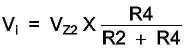
- the choice of voltage V Z3 is as follows: Vi ⁇ V Z3 ⁇ V Z2 . Since the transistor T1 is also blocked, the capacitor C4 charges through the resistors R2, R4.
- the transistor T4 When the transistor T4 is blocked, the energy stored in the primary choke of the primary winding ER of the transformer TR is transferred to the secondary winding ES of the latter and the capacitor C is charged through the diode D3.
- the charging voltage of the capacitor C is compared, through the voltage divider R11, R12 to the voltage V Z1 of the Zener diode Z1, by the comparator CO1.
- the comparator CO1 When there is equality of the two voltages at these inputs, the comparator CO1 becomes conductive, which stops the operation of the converter, as long as the capacitor C is sufficiently charged.
- the combination of resistors R9, R10 gives the value of the hysteresis voltage of the comparator CO1.
- the input E5 is set to level 0 by the signal produced at the output S5 of the control module , which ensures the blocking of the converter during this discharge.
- the injection time signal Si is manifested at the input E1 by switching to "0" of the potential present at this input.
- the signal Si causes the blocking of the transistor T10, which makes the transistor T11 conductive. Consequently, a current can flow through the transistor T11, the output terminal S6 of the module M1, the input E6 of the switch according to FIG. 4, the output terminal S1 of the switch and the injector 1 between earth and the positive pole of the battery 5.
- the capacitor C6 charges through the resistor R24.
- the signal Si of injection time at the input E1 of the module M1 causes the conduction of the comparator CO4 during the time that the capacitor C6 takes to charge at the voltage at the common terminal of the resistors R25 and R26.
- the comparator CO4 produces at its output S5 the blocking signal of the converter 8, which the latter receives at its input E5 (FIG. 3).
- the device according to the invention makes it possible to have only one high voltage source charging a single capacitor to supply several injectors.
- the use of high voltage switches such as I1, I2, I3 makes it possible to isolate the injectors 1, 2, 3 from the high voltage source and to extend the passage of current through it using the low voltage source supplying this device with a view to maintaining the injector. Consequently, the passage of a current through a switch and the recharging of the high-voltage capacitor C for the control of another switch can therefore partially overlap when the signal injection time signal Si is greater than l time interval for charging the capacitor C6 of the module M1 corresponding to the threshold voltage of the comparator CO4.
- the invention makes it possible to vary the injection time within significant limits.
- the device according to the invention can easily be controlled by a computer based on a microprocessor.
- the production of the device according to the invention does not require the use of expensive components.
Description
- L'invention concerne un dispositif de commande et de contrôle d'injecteurs de combustible d'un moteur à combustion interne avantageusement multicylindre et notamment à deux temps, du type décrit dans la 1ère partie de la revendication 1 (voir EP-A-34 076).
- La différence entre les dispositifs de commande et de contrôle d'injecteurs selon l'invention et selon EP-A- 34 076 réside dans le fait que dans le dispositif connu un dispositif commutateur est monté en série avec la bobine d'injection correspondante, aussi bien dans le circuit de décharge du condensateur que dans le circuit de courant de prolongation, le dispositif commutateur étant commandé par un signal périodique relatif au fonctionnement du moteur.
- Ceci signifie que le commutateur qui est formé par un circuit Darlington doit conduire à la fois le courant de pointe dû à la déchargfe du condensateur et le courant de maintien. Pour pouvoir accomplir cette fonction, il faut des transistors d'une technique délicate et couteuse.
- L'invention a pour objectif de proposer un dispositif qui ne nécessite par l'utilisation de tels transistors spécifiques, coûteux et ainsi désavantageux.
- L'invention permet d'atteindre ce but par les caractéristiques mentionnées dans la revendication 1.
- L'invention sera mieux comprise, et d'autres buts, détails et avantages de celle-ci apparaîtront plus clairement au cours de la description explicative qui va suivre faite en référence aux dessins schématiques annexés donnés uniquement à titre d'exemple illustrant un mode de réalisation de l'invention, et dans lesquels :
- La figure 1 montre sous forme d'un schéma bloc, la structure générale d'un dispositif de commande et de contrôle selon l'invention ;
- La figure 2 donne le schéma-bloc du bloc de commande 6 du dispositif représenté à la figure 1 ;
- La figure 3 montre le montage électrique du circuit de charge du condensateur haute tension selon la présente invention ;
- Les figures 4 et 5 illustrent le montage de deux modes de réalisation d'un circuit interrupteur selon la présente invention ; et
- Les figures 6 et 7 montrent le montage électrique des modules de commande sélective des interrupteurs respectivement selon les figures 4 et 5.
- La figure 1 montre à titre d'exemple la structure générale d'un dispositif de commande et de contrôle pour trois injecteurs 1, 2 et 3 équipant le moteur indiqué en 4. Ces injecteurs sont alimentés à partir d'une batterie 5 dont la borne de potentiel positif est reliée aux bornes A1, A2 et A3 respectivement des injecteurs 1, 2, 3 et commandés par le bloc de commande 6 auquel ils sont reliés par des bornes de sortie S1, S2 et S3. Le symbole de référence 7 désigne un calculateur qui est adapté pour donner au bloc de commande 6 les signaux de temps d'injection. Ces signaux sont appliqués aux entrées E1, E2 et E3 du bloc 6. On constate que la borne de potentiel positif A6 de la batterie 5 est également reliée à des bornes respectivement du bloc 6 et du calculateur 7.
- La figure 2 représente la structure d'un bloc de commande 6 et comporte un convertisseur B destiné à charger un condensateur C à une haute tension de par exemple 250 volts à partir de la tension d'alimentation de la batterie 5 connectée entre les bornes A6 et de masse, trois circuits interrupteur I1, I2, I3 chacun relié par sa borne de sortie S1, S2 ou S3 respectivement aux injecteurs 1, 2, 3, et trois modules M1, M2, M3 de commande sélective respectivement des interrupteurs I1, I2 et I3. On constate que chaque module M1, M2, M3 est relié par ses sorties S6, S7 respectivement aux entrées E6 et E7 de l'interrupteur I1, I2, I3 auquel il est associé. Chaque module est connecté à une borne d'entrée E1, E2 ou E3 du bloc de commande 6 et par une borne de sortie S5 à une entrée E5 du convertisseur B. Chacun des interrupteurs I1, I2, I3 est relié par sa borne d'entrée E4 à la borne S4 du condensateur C. Chaque interrupteur et module est relié au potentiel positif A6 de la batterie 5. Les modules de commande présentent en outre une borne de mise à la masse.
- La figure 3 montre le montage électrique du convertisseur B de charge du condensateur C à une haute tension de par exemple 250 volts, à partir de la tension de la batterie 5 de par exemple 12 volts. Le convertisseur a également pour fonction de maintenir chargé le condensateur C à cette haute tension. On constate que le condensateur C est monté dans le circuit de l'enroulement secondaire ES d'un transformateur TR comportant également une diode D3. On reconnaît dans ce circuit la borne S4 reliée aux entrées E4 des trois interrupteurs I1 I2, I3, comme cela ressort de la figure 2. L'enroulement primaire EP du transformateur TR est monté dans le circuit d'un organe de commande tel que le transistor T4. L'enroulement primaire EP est relié plus précisément entre la borne A6 de potentiel positif de la tension d'alimentation du convertisseur et l'électrode de drain du transistor. L'électrode de source de celui-ci est mise à la masse. Par son électrode de grille, le transistor T4 est relié aux émetteurs réunis de deux transistors T2, T3 de type de conductivité différente dont les collecteurs sont reliés respectivement à la borne A6 d'alimentation en tension continue de la batterie 5 et à la masse. La base du transistor T2 du type NPN est directement reliée à la base du transistor TS et par le montage en série d'une diode Zener Z4 et d'une diode D2 à l'électrode de drain du transistor T4. La base du transistor T2 est en outre reliée par une résistance R13, d'une litt, à la borne A6 par le montage en série de deux résistances R9, R10 et, d'autre part, aux sorties de deux comparateurs CO1, CO2. La sortie du comparateur CO2 est reliée à l'entrée de commande E5 connectée aux sorties S5 des trois modules de commande M1, M2, M3 (figure 2). L'entrée positive du comparateur CO2 est reliée, d'une part, à la masse par un condensateur C3 et, d'autre part, par une résistance R3 au point commun d'une résistance R2 et d'un potentiomètre R4. La borne libre de ce dernier est reliée au collecteur d'un transistor T1 et à la masse, par l'intermédiaire d'un condensateur C4. La base du transistor T1 est reliée à la masse par une résistance R5 et à la sortie du comparateur CO2 par une résistance R6. L'émetteur de T1 est mis à la masse. La borne libre de la résistance R2 est reliée à la borne d'alimentation A6 de la batterie 5 par une résistance R1. Une diode Zener Z2 est connectée entre la borne commune des résistances R1 et R2 et la masse. L'entrée négative du comparateur CO2 est reliée par un montage en parallèle d'une résistance R7 et d'une diode D1 à l'électrode de drain du transistor T4. De plus, une diode Zener Z3 est montée entre l'entrée négative du comparateur CO2 et la masse. Le comparateur CO1, également a deux entrées, est relié par l'intermédiaire d'une diode Zener Z1 à la borne de potentiel positif A6 et à la masse, par l'intermédiaire d'une résistance R14. Un condensateur C1 est connecté en parallèle à la diode Zener Z1. L'entrée positive du comparateur CO1 est reliée par une résistance R12 à la sortie S4 du condensateur C et, par une résistance R11, à la borne commune des deux résistances R9 et R10, ainsi que par un condensateur C2 à la borne A6.
- Les figures 4 et 5 montrent deux modes de réalisation d'un circuit interrupteur I1 identique aux interrupteurs I2 ou I3. Le mode de réalisation selon la figure 6 utilise un photo-coupleur à thyristor TH1, par exemple du type H11 C6. L'émetteur du photo-coupleur est connecté entre la borne positive A6 de la batterie 5 et l'entrée E7 de l'interrupteur (figure 2), par l'intermédiaire d'une résistance R16 de limitation du courant. Le photo-thyristor récepteur est monté entre la borne d'entrée E4 et la borne de sortie S1 de l'interrupteur. Une résistance R17 est monté entre la gachette et la borne E4. L'entrée E6 de l'interrupteur est reliée à la borne de sortie S1 par un montage en série d'une résistance R18 et d'une diode D5. L'interrupteur selon la figure 5 utilise un transistor haute tension T6 du type C-MOS. Le circuit source-drain est relié entre les bornes d'entrée E4 et de sortie S1. La grille du transistor T6 est reliée, d'une part, par une diode Zener Z5 à la source du transistor et, d'autre part, par une résistance R19 au collecteur d'un transistor T7 dont l'émetteur est relié au potentiel positif A6 de la batterie 5. La base du transistor T7 est connectée par une résistance R20 à l'entrée E7 de l'interrupteur, et par une résistance R21 à la borne d'alimentation A6. L'entrée E6 de l'interrupteur est reliée à l'électrode de drain du transistor T6, à travers le montage en série de la diode D5 et de la résistance R18 de la figure 4.
- La figure 6 montre le schéma électrique d'un module de commande M1 identique au module M2 ou M3, destiné à commander un interrupteur tel que représenté à la figure 4. Le module de commande comprend deux comparateurs CO3, CO4 dont les entrées respectivement négative et positive sont reliées, par l'intermédiaire d'un condensateur C6 à la borne d'entrée E1 qui reçoit le signal de temps d'injection en provenance du calculateur 7 (figure 1). ces entrées sont également connectées à la borne de potentiel positif A6 de la batterie 5, par un montage en parallèle d'une résistance R24 et d'une diode D6. Les bornes A6 et de masse du module sont reliées par un montage en série formé des trois résistances R25, R20 et R27. La borne commune des résistances R25 et R26 est reliée à l'entrée négative du comparateur CO4. tandis que la borne commune des résistances R26 et R27 est reliée à l'entrée positive du comparateur CO3. La sortie de ce dernier est reliée à la grille d'un transistor du type à effet de champ T9 connecté par ces électrodes de source et de drain respectivement à la masse et à la borne de sortie S7 de commande du circuit interrupteur associé. D'autre part, la sortie du comparateur CO3 est reliée à la borne A6 de potentiel d'alimentation positif, par une résistance R28. La sortie du comparateur CO4 est reliée à la borne de sortie S5 à connecter à l'entrée E5 du convertisseur 8 (figures 2, 3).
- L'entrée E1 du module de commande est encore reliée par une résistance R29 à la grille d'un transistor à effet de champ T10. Cette grille est également reliée par une résistance R30 à la borne d'alimentation A6. Les électrodes de source et de drain du transistor T10 sont reliées respectivement à la masse et, par l'intermédiaire d'une résistance R31, à la borne A6. L'électrode de drain attaque en plus, par l'intermédiaire d'une résistance R32 la base d'un transistor T11 qui est relié par son émetteur à la masse et par son collecteur à la borne de sortie S6 du module de commande, destinée à être reliée à l'entrée E6 de l'interrupteur associé. La base et le collecteur des transistors T11 sont reliés par une diode Zener Z6.
- la figure 7 montre un autre mode de réalisation d'un module de commande M1, M2 ou M3, par exemple du module M1 destiné à commander un interrupteur tel que représenté à la figure 5, qui se distingue du module de commande selon la figure 6 par le fait qu'il n'utilise qu'un seul comparateur CO5 dont l'entrée positive est reliée au condensateur C6, comme le comparateur CO4 de la figure 6. L'entrée négative du comparateur CO5 est connectée à la borne commune de deux résistances R33, R34 qui sont connectées par leurs bornes libres respectivement à la borne A6 d'alimentation et à la masse. La sortie du comparateur CO5 est directement reliée à la sortie S7 du module et, par l'intermédiaire d'une diode D7, à la sortie S5.
- On décrira ci-après le fonctionnement du dispositif de commande et de contrôle d'une pluralité d'injecteurs, qui vient d'être décrit :
- Le convertisseur haute tension 8 a pour fonction de charger le condensateur C à la haute tension et le maintenir chargé. Pour commander un des trois interrupteurs, par exemple l'interrupteur 1, le calculateur 7 applique un signal de temps d'injection SI à l'entrée E1 du bloc de commande 6. En réponse à ce signal, ce module ferme le circuit interrupteur I1, ce qui provoque la décharge du condensateur C à travers l'injecteur 1, via cet interrupteur, et le blocage du convertisseur 8 pendant le temps de cette décharge. Le module de commande M1 assure le maintien d'un courant dans l'injecteur durant tout le temps d'injection. A cette fin, même après la décharge du condensateur C, l'injecteur peut être traversé par un courant en provenance de la batterie 5 jusqu'à la fin du signal SI de temps d'injection. Ainsi la recharge du condensateur C pour la commande de l'interrupteur suivant peut déjà débuter avant la fin de l'injection précédente. Le cycle, qui vient d'être décrit, se répète successivement pour les autres injecteurs 2, 3 via les entrées E2 et E3 mettant en oeuvre respectivement les modules de commande M2, M3 et les interrupteurs I2 et I3, dans l'ordre imposé par le calculateur 7.
- Concernant le fonctionnement du convertisseur 8, la charge du condensateur C se fait en plusieurs cycles. Au début d'un tel cycle, les comparateurs CO1 et CO2 ne conduisent pas. Par contre, le transistor T1 est conducteur et courtcircuite le condensateur C4. Le transistor T4 conduit également, via le transistor T2, polarisé par les résistances R13, R9 et R10. Un courant s'établit dans l'enroulement primaire EP du transformateur TR. Lorsque la tension drain-source VDS du transistor T4, qui est égale au produit du courant traversant l'enroulement primaire par la résistance de T4, atteint la valeur
- Au blocage du transistor T4, l'énergie emmagasinée dans la self primaire de l'enroulement primaire ER du transformateur TR est transféré à l'enroulement secondaire ES de celui-ci et le condensateur C est chargé à travers la diode D3. La tension de charge du condensateur C est comparée, à travers le diviseur de tension R11, R12 à la tension VZ1 de la diode Zener Z1, par le comparateur CO1. Lorsqu'il y a égalité des deux tensions à ces entrées, le comparateur CO1 devient conducteur, ce qui arrête le fonctionnement du convertisseur, tant que le condensateur C est suffisamment chargé. La combinaison des résistances R9, R10 donne la valeur de la tension d'hystéresis du comparateur CO1.
- Lorsque le condensateur C se décharge lors de la fermeture d'un interrupteur I1, I2 ou I3, sous la commande du module de commande associé, l'entrée E5 est mise au niveau 0 par le signal produit à la sortie S5 du module de commande, ce qui assure le blocage du convertisseur le temps de cette décharge.
- En se référant aux figures 4 et 6, on expliquera ci-après l'établissement du circuit de décharge du condensateur C du convertisseur 8 à travers l'injecteur 1, à la suite d'un signal appliqué à l'entrée E1 du bloc de commande 6 par le calculateur 7. Dans l'exemple représenté, le signal de temps d'injection Si se manifeste à l'entrée E1 par le passage à "0" du potentiel présent à cette entrée. Le signal Si provoque le blocage du transistor T10, ce qui rend conducteur le transistor T11. Par conséquent, un courant peut s'écouler à travers le transistor T11, la borne de sortie S6 du module M1, l'entrée E6 de l'interrupteur selon la figure 4, la borne de sortie S1 de l'interrupteur et l'injecteur 1 entre la masse et le pôle positif de la batterie 5. D'autre part, au moment de passage de l'entrée E1 à "0", le condensateur C6 se charge à travers la résistance R24. Pendant le temps mis par ce condensateur pour se charger à la tension égale à celle présente aux bornes de la résistance R27, le comparateur CO3 ne conduit plus et le transistor T9 devient conducteur, polarisé par la résistance R28, et produit un signal de commande à sa sortie S7. Ce signal sera transmis à l'entrée E7 de l'interrupteur I1 et active par exemple pendant 10 à 20 µsec l'émetteur du photo-thyristor TH1. Le récepteur du photo-thyristor devient conducteur et le restera tant que le condensateur C ne sera pas déchargé, ce qui établit le circuit de décharge du condensateur C à travers l'interrupteur I1 (figure 2). Le signal Si de temps d'injection à l'entrée E1 du module M1 provoque la conduction du comparateur CO4 pendant la durée de temps que met le condensateur C6 pour se charger à la tension à la borne commune des résistances R25 et R26. Pendant cet intervalle de temps, le comparateur CO4 produit à sa sortie S5 le signal de blocage du convertisseur 8, que celui-ci reçoit à son entrée E5 (figure 3).
- Lorsque le signal Si de temps d'interruption cesse, le transistor T10 devient conducteur et bloque le transistor T11, la diode Zener Z6 protégeant celui-ci contre les surtensions. Le condensateur C6 se décharge à travers les résistances R30, R29 et la diode D6.
- Dans le cas d'utilisation de l'interrupteur selon la figure 5 et d'un module de commande selon la figure 7, les opérations sont les mêmes. La différence réside uniquement au niveau de la structure des circuits. On constate notamment que le circuit du modules selon la figure 7 est simplifié par rapport au mode de réalisation représenté à la figure 6.
- On comprend aisément que le dispositif selon l'invention permet de n'avoir qu'une seule source de tension élevée chargeant un condensateur unique pour alimenter plusieurs injecteurs. De plus, l'emploi d'interrupteurs haute tension tel que I1, I2, I3 permet d'isoler les injecteurs 1, 2, 3 de la source haute tension et de prolonger le passage du courant dans celui-ci à l'aide de la source basse tension alimentant ce dispositif en vue d'un maintien de l'injecteur. Par conséquent le passage d'un courant à travers un interrupteur et la recharge du condensateur haute tension C en vue de la commande d'un autre interrupteur peuvent donc se recouvrir partiellement lorsque le signal de temps d'injection du signal Si est supérieur à l'intervalle de temps de charge du condensateur C6 du module M1 correspondant à la tension du seuil du comparateur CO4. L'invention rend possible la variation du temps d'injection dans des limites importantes. Le dispositif selon l'invention peut facilement être commandé par un calculateur à base de micro-processeur. En outre la réalisation du dispositif selon l'invention ne nécessite pas l'emploi de composants coûteux.
Claims (8)
Applications Claiming Priority (2)
| Application Number | Priority Date | Filing Date | Title |
|---|---|---|---|
| FR8718234 | 1987-12-28 | ||
| FR8718234A FR2625260B1 (fr) | 1987-12-28 | 1987-12-28 | Dispositif de commande et de controle d'injecteurs de combustible d'un moteur a combustion interne multicylindre notamment a deux temps |
Publications (2)
| Publication Number | Publication Date |
|---|---|
| EP0323318A1 EP0323318A1 (fr) | 1989-07-05 |
| EP0323318B1 true EP0323318B1 (fr) | 1992-05-06 |
Family
ID=9358354
Family Applications (1)
| Application Number | Title | Priority Date | Filing Date |
|---|---|---|---|
| EP19880403271 Expired - Lifetime EP0323318B1 (fr) | 1987-12-28 | 1988-12-21 | Dispositif de commande et de contrôle d'injecteurs de combustible d'un moteur à combustion interne multicylindre notamment à deux temps |
Country Status (3)
| Country | Link |
|---|---|
| EP (1) | EP0323318B1 (fr) |
| DE (1) | DE3870844D1 (fr) |
| FR (1) | FR2625260B1 (fr) |
Families Citing this family (1)
| Publication number | Priority date | Publication date | Assignee | Title |
|---|---|---|---|---|
| FR2667357A1 (fr) * | 1990-09-28 | 1992-04-03 | Renault | Dispositif de commande d'injecteurs de combustible dans un moteur a combustion interne. |
Family Cites Families (5)
| Publication number | Priority date | Publication date | Assignee | Title |
|---|---|---|---|---|
| SU801130A1 (ru) * | 1979-04-26 | 1981-01-30 | Предприятие П/Я В-2309 | Устройство дл форсированногоВКлючЕНи элЕКТРОМАгНиТА |
| US4327693A (en) * | 1980-02-01 | 1982-05-04 | The Bendix Corporation | Solenoid driver using single boost circuit |
| US4355619A (en) * | 1980-10-01 | 1982-10-26 | The Bendix Corporation | Fast response two coil solenoid driver |
| US4479161A (en) * | 1982-09-27 | 1984-10-23 | The Bendix Corporation | Switching type driver circuit for fuel injector |
| FR2538942B1 (fr) * | 1982-12-29 | 1989-05-05 | Renault | Dispositif de commande d'organe(s) electromagnetique(s) a actionnement rapide, tel(s) qu'electrovanne(s) ou injecteur(s) |
-
1987
- 1987-12-28 FR FR8718234A patent/FR2625260B1/fr not_active Expired - Fee Related
-
1988
- 1988-12-21 EP EP19880403271 patent/EP0323318B1/fr not_active Expired - Lifetime
- 1988-12-21 DE DE8888403271T patent/DE3870844D1/de not_active Expired - Fee Related
Also Published As
| Publication number | Publication date |
|---|---|
| FR2625260A1 (fr) | 1989-06-30 |
| FR2625260B1 (fr) | 1993-09-24 |
| DE3870844D1 (de) | 1992-06-11 |
| EP0323318A1 (fr) | 1989-07-05 |
Similar Documents
| Publication | Publication Date | Title |
|---|---|---|
| FR2607278A1 (fr) | Circuit integrable de regulation de courant dans une charge inductive et son application a la commande de bobine d'allumage d'un moteur a combustion interne | |
| FR2630271A1 (fr) | Dispositif d'alimentation electrique sous tension elevee du circuit auxiliaire d'un vehicule automobile | |
| FR2461117A1 (fr) | Montage de connexion pour installation electrique, notamment l'installation d'allumage d'un vehicule automobile | |
| FR2549899A1 (fr) | Procede et dispositif pour commander la position d'un clapet d'etranglement dans la tubulure d'aspiration d'un moteur a combustion interne | |
| EP0323318B1 (fr) | Dispositif de commande et de contrôle d'injecteurs de combustible d'un moteur à combustion interne multicylindre notamment à deux temps | |
| EP1067608B1 (fr) | Dispositif et procédé de commande d'un actuateur piezo-électrique | |
| FR2520890A1 (fr) | Dispositif de controle de la vitesse d'embrayage d'un embrayage electromagnetique | |
| FR2826801A1 (fr) | Systeme de commande de generateur de vehicule | |
| EP0163332B1 (fr) | Relais statique pour courant continu | |
| FR2927740A1 (fr) | Appareil de commande destine a un alternateur embarque dans un vehicule | |
| EP0021867B1 (fr) | Dispositif d'alimentation à découpage régulé contre les variations de tension d'entrée et de puissance de sortie, notamment pour récepteur de télévision | |
| FR2674382A1 (fr) | Dispositif de regulation de tension de sortie pour alternateur. | |
| US4403592A (en) | Engine ignition system with automatic timing shift | |
| FR2533263A1 (fr) | Dispositif de commande d'organes electromagnetiques a actionnement rapide, tels qu'electrovannes ou injecteurs pour moteurs a combustion interne | |
| US4275702A (en) | Ignition system for an internal combustion engine | |
| EP0427594B1 (fr) | Installation d'alimentation de charges inductives en impulsions, à limitation de tension | |
| CH492872A (fr) | Dispositif d'allumage électronique pour moteur à explosion | |
| EP0478436A1 (fr) | Dispositif de commande d'injecteurs de combustible dans un moteur à combustion interne | |
| FR2467996A1 (fr) | Dispositif de branchement pour limiter la vitesse de rotation d'un moteur | |
| EP0187071B1 (fr) | Système électronique d'élaboration d'un signal synchrone d'un signal d'allumage de moteur à combustion interne | |
| EP0046092B1 (fr) | Dispositif électronique de commande d'allumage de moteur à combustion interne | |
| EP1828584B1 (fr) | Dispositif de commande electronique pour actionneurs piezo-electriques ultrasonores | |
| FR2524728A1 (fr) | Dispositif de commande du temps de conduction pour circuit d'allumage electronique de moteur a explosion | |
| FR2476755A1 (fr) | Systeme d'allumage pour des moteurs a combustion interne | |
| FR2564263A1 (fr) | Relais statique pour courant continu basse tension |
Legal Events
| Date | Code | Title | Description |
|---|---|---|---|
| PUAI | Public reference made under article 153(3) epc to a published international application that has entered the european phase |
Free format text: ORIGINAL CODE: 0009012 |
|
| AK | Designated contracting states |
Kind code of ref document: A1 Designated state(s): DE GB IT |
|
| 17P | Request for examination filed |
Effective date: 19891229 |
|
| 17Q | First examination report despatched |
Effective date: 19910125 |
|
| GRAA | (expected) grant |
Free format text: ORIGINAL CODE: 0009210 |
|
| AK | Designated contracting states |
Kind code of ref document: B1 Designated state(s): DE GB IT |
|
| REF | Corresponds to: |
Ref document number: 3870844 Country of ref document: DE Date of ref document: 19920611 |
|
| ITF | It: translation for a ep patent filed |
Owner name: DE DOMINICIS & MAYER S.R.L. |
|
| GBT | Gb: translation of ep patent filed (gb section 77(6)(a)/1977) | ||
| PLBE | No opposition filed within time limit |
Free format text: ORIGINAL CODE: 0009261 |
|
| STAA | Information on the status of an ep patent application or granted ep patent |
Free format text: STATUS: NO OPPOSITION FILED WITHIN TIME LIMIT |
|
| 26N | No opposition filed | ||
| PGFP | Annual fee paid to national office [announced via postgrant information from national office to epo] |
Ref country code: GB Payment date: 19961212 Year of fee payment: 9 |
|
| PGFP | Annual fee paid to national office [announced via postgrant information from national office to epo] |
Ref country code: DE Payment date: 19961231 Year of fee payment: 9 |
|
| PG25 | Lapsed in a contracting state [announced via postgrant information from national office to epo] |
Ref country code: GB Free format text: LAPSE BECAUSE OF NON-PAYMENT OF DUE FEES Effective date: 19971221 |
|
| GBPC | Gb: european patent ceased through non-payment of renewal fee |
Effective date: 19971221 |
|
| PG25 | Lapsed in a contracting state [announced via postgrant information from national office to epo] |
Ref country code: DE Free format text: LAPSE BECAUSE OF NON-PAYMENT OF DUE FEES Effective date: 19980901 |
|
| PG25 | Lapsed in a contracting state [announced via postgrant information from national office to epo] |
Ref country code: IT Free format text: LAPSE BECAUSE OF NON-PAYMENT OF DUE FEES;WARNING: LAPSES OF ITALIAN PATENTS WITH EFFECTIVE DATE BEFORE 2007 MAY HAVE OCCURRED AT ANY TIME BEFORE 2007. THE CORRECT EFFECTIVE DATE MAY BE DIFFERENT FROM THE ONE RECORDED. Effective date: 20051221 |