EP0322294B2 - Procédé de montage d'un accumulateur hydropneumatique - Google Patents
Procédé de montage d'un accumulateur hydropneumatique Download PDFInfo
- Publication number
- EP0322294B2 EP0322294B2 EP19880403230 EP88403230A EP0322294B2 EP 0322294 B2 EP0322294 B2 EP 0322294B2 EP 19880403230 EP19880403230 EP 19880403230 EP 88403230 A EP88403230 A EP 88403230A EP 0322294 B2 EP0322294 B2 EP 0322294B2
- Authority
- EP
- European Patent Office
- Prior art keywords
- bowl
- retaining ring
- cover
- membrane
- mounting
- Prior art date
- Legal status (The legal status is an assumption and is not a legal conclusion. Google has not performed a legal analysis and makes no representation as to the accuracy of the status listed.)
- Expired - Lifetime
Links
Images

Classifications
-
- F—MECHANICAL ENGINEERING; LIGHTING; HEATING; WEAPONS; BLASTING
- F15—FLUID-PRESSURE ACTUATORS; HYDRAULICS OR PNEUMATICS IN GENERAL
- F15B—SYSTEMS ACTING BY MEANS OF FLUIDS IN GENERAL; FLUID-PRESSURE ACTUATORS, e.g. SERVOMOTORS; DETAILS OF FLUID-PRESSURE SYSTEMS, NOT OTHERWISE PROVIDED FOR
- F15B1/00—Installations or systems with accumulators; Supply reservoir or sump assemblies
- F15B1/02—Installations or systems with accumulators
- F15B1/04—Accumulators
- F15B1/08—Accumulators using a gas cushion; Gas charging devices; Indicators or floats therefor
- F15B1/10—Accumulators using a gas cushion; Gas charging devices; Indicators or floats therefor with flexible separating means
- F15B1/12—Accumulators using a gas cushion; Gas charging devices; Indicators or floats therefor with flexible separating means attached at their periphery
- F15B1/14—Accumulators using a gas cushion; Gas charging devices; Indicators or floats therefor with flexible separating means attached at their periphery by means of a rigid annular supporting member
-
- B—PERFORMING OPERATIONS; TRANSPORTING
- B60—VEHICLES IN GENERAL
- B60G—VEHICLE SUSPENSION ARRANGEMENTS
- B60G2206/00—Indexing codes related to the manufacturing of suspensions: constructional features, the materials used, procedures or tools
- B60G2206/01—Constructional features of suspension elements, e.g. arms, dampers, springs
- B60G2206/40—Constructional features of dampers and/or springs
- B60G2206/42—Springs
- B60G2206/422—Accumulators for hydropneumatic springs
- B60G2206/4222—Accumulators for hydropneumatic springs with a flexible separating wall; Membrane construction
-
- F—MECHANICAL ENGINEERING; LIGHTING; HEATING; WEAPONS; BLASTING
- F15—FLUID-PRESSURE ACTUATORS; HYDRAULICS OR PNEUMATICS IN GENERAL
- F15B—SYSTEMS ACTING BY MEANS OF FLUIDS IN GENERAL; FLUID-PRESSURE ACTUATORS, e.g. SERVOMOTORS; DETAILS OF FLUID-PRESSURE SYSTEMS, NOT OTHERWISE PROVIDED FOR
- F15B2201/00—Accumulators
- F15B2201/20—Accumulator cushioning means
- F15B2201/205—Accumulator cushioning means using gas
-
- F—MECHANICAL ENGINEERING; LIGHTING; HEATING; WEAPONS; BLASTING
- F15—FLUID-PRESSURE ACTUATORS; HYDRAULICS OR PNEUMATICS IN GENERAL
- F15B—SYSTEMS ACTING BY MEANS OF FLUIDS IN GENERAL; FLUID-PRESSURE ACTUATORS, e.g. SERVOMOTORS; DETAILS OF FLUID-PRESSURE SYSTEMS, NOT OTHERWISE PROVIDED FOR
- F15B2201/00—Accumulators
- F15B2201/30—Accumulator separating means
- F15B2201/315—Accumulator separating means having flexible separating means
- F15B2201/3151—Accumulator separating means having flexible separating means the flexible separating means being diaphragms or membranes
-
- F—MECHANICAL ENGINEERING; LIGHTING; HEATING; WEAPONS; BLASTING
- F15—FLUID-PRESSURE ACTUATORS; HYDRAULICS OR PNEUMATICS IN GENERAL
- F15B—SYSTEMS ACTING BY MEANS OF FLUIDS IN GENERAL; FLUID-PRESSURE ACTUATORS, e.g. SERVOMOTORS; DETAILS OF FLUID-PRESSURE SYSTEMS, NOT OTHERWISE PROVIDED FOR
- F15B2201/00—Accumulators
- F15B2201/30—Accumulator separating means
- F15B2201/315—Accumulator separating means having flexible separating means
- F15B2201/3156—Accumulator separating means having flexible separating means characterised by their attachment
-
- F—MECHANICAL ENGINEERING; LIGHTING; HEATING; WEAPONS; BLASTING
- F15—FLUID-PRESSURE ACTUATORS; HYDRAULICS OR PNEUMATICS IN GENERAL
- F15B—SYSTEMS ACTING BY MEANS OF FLUIDS IN GENERAL; FLUID-PRESSURE ACTUATORS, e.g. SERVOMOTORS; DETAILS OF FLUID-PRESSURE SYSTEMS, NOT OTHERWISE PROVIDED FOR
- F15B2201/00—Accumulators
- F15B2201/40—Constructional details of accumulators not otherwise provided for
- F15B2201/41—Liquid ports
- F15B2201/411—Liquid ports having valve means
-
- F—MECHANICAL ENGINEERING; LIGHTING; HEATING; WEAPONS; BLASTING
- F15—FLUID-PRESSURE ACTUATORS; HYDRAULICS OR PNEUMATICS IN GENERAL
- F15B—SYSTEMS ACTING BY MEANS OF FLUIDS IN GENERAL; FLUID-PRESSURE ACTUATORS, e.g. SERVOMOTORS; DETAILS OF FLUID-PRESSURE SYSTEMS, NOT OTHERWISE PROVIDED FOR
- F15B2201/00—Accumulators
- F15B2201/40—Constructional details of accumulators not otherwise provided for
- F15B2201/415—Gas ports
-
- F—MECHANICAL ENGINEERING; LIGHTING; HEATING; WEAPONS; BLASTING
- F15—FLUID-PRESSURE ACTUATORS; HYDRAULICS OR PNEUMATICS IN GENERAL
- F15B—SYSTEMS ACTING BY MEANS OF FLUIDS IN GENERAL; FLUID-PRESSURE ACTUATORS, e.g. SERVOMOTORS; DETAILS OF FLUID-PRESSURE SYSTEMS, NOT OTHERWISE PROVIDED FOR
- F15B2201/00—Accumulators
- F15B2201/40—Constructional details of accumulators not otherwise provided for
- F15B2201/43—Anti-extrusion means
- F15B2201/435—Anti-extrusion means being fixed to the separating means
Definitions
- the present invention relates to a method of mounting a hydropneumatic accumulator comprising an envelope consisting of a bowl and a lid linked by a weld bead, inside which is mounted in leaktight manner a membrane separating the envelope between a first chamber containing liquid and a second chamber containing gas, the membrane being mounted on a retaining ring by means of a bead engaged in a groove in the retaining ring which ensures the tightening of the membrane to the inside the envelope.
- Such an arrangement is not suitable for producing a weld bead without adding material.
- Document DE-A-3 207 754 describes a similar hydropneumatic accumulator in which the upper part of the bowl and the lower part of the cover each have a corresponding conical part of the retaining ring. In this accumulator, the weld bead is made with the addition of material.
- the present invention relates to a method of mounting a hydropneumatic accumulator which allows welding without addition of material, for example by laser beams.
- This process which is of the type mentioned in the preamble of claim 1, is characterized in that the retaining ring is placed inside the bowl so that its maximum diameter, resulting from the intersection of two reverse conical parts, is located to the right of the weld bead to be made and that, the cover being positioned on the conical surface of the retaining ring, there is a clearance between the contact surfaces of the bowl and of the cover so that the contact between the conical surfaces the retaining ring, the bowl and the cover is ensured by the plating of the contact surfaces bowl / cover for the welding, and that this welding is carried out without addition of material.
- This process allows the centering of the lid and the bowl on the retaining ring which is positively positioned between the bowl and the lid.
- the weld bead may have an interruption so as to bring the zones of contact between the conical surfaces of the retaining ring, the bowl and the cover to the atmosphere in order to ensure a better seal.
- the hydropneumatic accumulator comprises a bowl 1 and a cover 2 made of hot-rolled extra mild sheet steel, allowing deep drawing.
- a membrane 3 which separates the envelope into a first chamber 4 filled with liquid and a second chamber 5 filled with gas; this membrane is made of elastomer, for example UREPAN or EPICHLORYDRINE if the hydraulic fluid is mineral oil.
- the membrane 3 has a bead 8 which seals between the two chambers 4 and 5 by clamping between the cylindrical part 1 a of the lower bowl, and the cylindrical part 9 a of a retaining ring 9.
- a connector 10 for connection to the hydraulic circuit is laser welded to the lower bowl. After inflation with nitrogen, a filling orifice 11 formed in the cover 2 is closed by a plug 12 made of mild steel, for example a ball, electrically welded
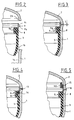
- the part of the retaining ring 9 external to the membrane 3 has an external wall in double cone 9 b -9 c : the upper part of the bowl 1 and the lower part of the cover 2 have a conical surface 1 b or 2 b cooperating when the accumulator is mounted, with the double cone 9 b -9 c of the ring 9.
- the assembly is carried out by first fitting the bead 8 of the membrane into the retaining ring 9.
- the membrane 3 / ring 9 assembly is lowered into the bowl 1.
- the conical bearing 1 b using the bead 8 to engage in the cylindrical portion 1a of the bowl 1, until the contact of the cone 9 b on the common conical 1b.
- the sealing is then assured by the clamping of the bead 8 between the cylindrical portion 1a of the bowl and the cylindrical portion 9a of the holding rin e 9.
- the cover 2 is then set up by plating its conical bearing surface 2 b on the cone 9 c of the retaining ring.
- the dimension chains have been established in such a way that the retaining ring is always in contact with the conical surfaces of the bowl and the lid.
- the result between the edges of the bowl and the lid is a dimension L varying from 0 to a few tenths of a millimeter.
- the embodiment of Figure 5 does not require a sealing condition of the weld.
- the retaining ring 9 is extended at 9 d towards the cover 2 so as to be able to place a seal 15 between the ring and the cover.
- the weld bead is voluntarily interrupted over an area of a few millimeters, area indicated in 16, which puts the area of contact of the cones into the atmosphere. After filling the chamber 5, the internal nitrogen pressure pushes the seal 15 and the bead 8, without however extruding them since there is contact with metal parts, but these elements will always be in the sealing position as long as there will be an internal pressure.
Landscapes
- Engineering & Computer Science (AREA)
- Physics & Mathematics (AREA)
- Fluid Mechanics (AREA)
- Mechanical Engineering (AREA)
- General Engineering & Computer Science (AREA)
- Supply Devices, Intensifiers, Converters, And Telemotors (AREA)
Description
- La présente invention concerne un procédé de montage d'un accumulateur hydropneumatique comportant une enveloppe constituée d'un bol et d'un couvercle liés par un cordon de soudure, à l'intérieur de laquelle est montée de manière étanche une membrane séparant l'enveloppe entre une première chambre contenant du liquide et une deuxième chambre contenant du gaz, la membrane étant montée sur une bague de maintien par l'intermédiaire d'un bourrelet engagé dans une gorge de la bague de maintien qui assure le serrage de la membrane à l'intérieur de l'enveloppe.
- Un accumulateur de ce genre est décrit dans le brevet français 2 230 882. Dans cet accumulateur connu, la partie de la bague de maintien extérieure sphérique présentant face au cordon de soudure une surface concave destinée à recevoir une matière repoussant la soudure.
- Une telle disposition n'est pas appropriée à la réalisation d'un cordon de soudure sans apport de matière.
- Le document DE-A- 3 207 754 décrit un accumulateur hydropneumatique analogue dans lequel la partie supérieure du bol et la partie inférieure du couvercle présentent chacune une partie conique correspondante de la bague de maintien. Dans cet accumulateur, le cordon de soudure est effectué avec apport de matière.
- La présente invention a pour objet un procédé de montage d'un accumulateur hydropneumatique qui permet une soudure sans apport de matière, par exemple par faisceaux laser.
- Ce procédé qui est du type mentionné dans le préambule de la revendication 1 est caractérisé en ce qu'on dispose la bague de maintien à l'intérieur du bol de façon que son diamètre maximal, résultant de l'intersection de deux parties coniques inverses, se trouve au droit du cordon de soudure à réaliser et que, le couvercle étant positionné sur la portée conique de la bague de maintien, il existe un jeu entre les surfaces de contact du bol et du couvercle de manière que le contact entre les surfaces coniques de la bague de maintien, du bol et du couvercle soit assuré par le placage des surfaces de contact bol/couvercle pour la soudure, et qu'on assure cette soudure sans apport de matière.
- Ce procédé permet le centrage du couvercle et du bol sur la bague de maintien qui est positionnée de manière positive entre le bol et le couvercle.
- Le cordon de soudure peut présenter une interruption de manière à réaliser une mise à l'atmosphère des zones de contact entre les portées coniques de la bague de maintien, du bol et du couvercle afin d'assurer une meilleure étanchéité.
- On a décrit ci-après, à titre d'exemple non limitatif, divers modes de réalisation de l'accumulateur selon l'invention, avec référence aux dessins annexés dans lesquels :
- La Figure 1 représente un premier mode de réalisation partiellement en élévation, partiellement en coupe axiale :
- Les Figures 2 et 3 montrent en coupe axiale un détail de l'accumulateur de la Figure 1, lors de son montage ;
- Les Figures 4 et 5 sont des vues en coupe axiale d'un détail de deux autres modes de réalisation.
- Tel qu'il est représenté à la Figure 1, l'accumulateur hydropneumatique comprend un bol 1 et un couvercle 2 en tôle d'acier extra doux laminé à chaud, permettant les emboutis profonds. A l'intérieur de l'enveloppe se trouve une membrane 3 qui sépare l'enveloppe en une première chambre 4 remplie de liquide et une deuxième chambre 5 remplie de gaz ; cette membrane est en élastomère, par exemple de l'UREPAN ou de l'EPICHLORYDRINE si le liquide hydraulique est de l'huile minérale. Elle est munie d'un clapet 6, en matière plastique dure, boutonné dans un logement aménagé dans la membrane. La fonction du clapet est d'obturer un trou 7 du bol 1 quand il n'y a plus de pression hydraulique afin d'éviter l'extrusion de l'élastomère dans le trou. La membrane 3 présente un bourrelet 8 qui assure l'étanchéité entre les deux chambres 4 et 5 par serrage entre la partie cylindrique 1a du bol inférieur, et la partie cylindrique 9a d'une bague de maintien 9. Un embout 10 de raccordement au circuit hydraulique est soudé par laser sur le bol inférieur. Après gonflage à l'azote, un orifice de remplissage 11 ménagé dans le couvercle 2 est obturé par un bouchon 12 en acier doux, par exemple une bille, soudé électriquement
- Comme on le voit plus particulièrement aux Figures 2 et 3, la partie de la bague de maintien 9 extérieure à la membrane 3 présente une paroi extérieure en double cône 9b-9c : la partie supérieure du bol 1 et la partie inférieure du couvercle 2 présentent une portée conique 1b ou 2b coopérant lorsque l'accumulateur est monté, avec le double cône 9b-9c de la bague 9.
- Le montage s'effectue en emmanchant d'abord le bourrelet 8 de la membrane dans la bague de maintien 9. L'ensemble membrane 3 / bague 9 est descendu dans le bol 1. En exerçant un effort axial sur cet ensemble, la portée conique 1b aide le bourrelet 8 à s'engager dans la partie cylindrique 1a du bol 1 jusqu'à l'obtention du contact du cône 9b sur la porté conique 1b. L'étanchéité est alors assurée par le serrage du bourrelet 8 entre la partie cylindrique 1a du bol et la partie cylindrique 9a de la bague de maintien 9. Le couvercle 2 est ensuite mis en place par placage de sa portée conique 2b sur le cône 9c de la bague de maintien. Les chaînes de cotes ont été établies de telle façon que la bague de maintien soit toujours en contact sur les portées coniques du bol et du couvercle. Il en résulte entre les tranches du bol et du couvercle une cote L variant de 0 à quelques dizièmes de millimètre. Pour assurer la formation d'un cordon de soudure étanche 13 par laser donc sans apport de métal, il faut qu'il y ait placage de la tranche du bol sur la tranche du couvercle. Ce placage est obtenu en exerçant un effort axial sur le couvercle jusqu'à déformation de la portée conique 9c de la bague de maintien.
- Pour certaines conditions d'utilisation, et notamment pour des minima et des maxima de températures moins sévères, on peut se contenter d'une membrane en polyuréthane injectable, genre de DESMOPAN, qui revient moins cher, tant en coût matière qu'en coût de transformation. Le matériau ne possédant pas la souplesse du caoutchouc, on peut obtenir l'étanchéité par adjonction d'un élément élastique d'étanchéité par exemple un joint torique 14 engagé dans un décrochement prévu sur la face de la membrane 3 tournée vers le bol 1, au niveau de son bourrelet 8 (Figure 4).
- Le mode de réalisation de la Figure 5 ne nécessite pas de condition d'étanchéité de la soudure. La bague de maintien 9 est prolongée en 9d vers le couvercle 2 de façon à pouvoir placer un joint d'étanchéité 15 entre la bague et le couvercle. On interrompt volontairement le cordon de soudure sur une zone de quelques millimètres, zone indiquée en 16, ce qui met la zone de contact des cônes à l'atmosphère. Après remplissage de la chambre 5, la pression d'azote interne pousse le joint 15 et le bourrelet 8, sans les extruder pour autant puisqu'il y a contact des pièces métalliques, mais ces éléments seront toujours en position d'étanchéité tant qu'il règnera une pression intérieure.
Claims (4)
- Procédé de montage d'un accumulateur hydropneumatique comportant une enveloppe constituée d'un bol (1) et d'un couvercle (2) liés par un cordon de soudure (13), à l'intérieur de laquelle est montée de manière étanche une membrane (3) séparant l'enveloppe entre une première chambre (4) remplie de liquide et une deuxième chambre (5) remplie de gaz, la membrane (3) étant montée sur une bague de maintien (9) par l'intermédiaire d'un bourrelet (8) engagé dans une gorge de la bague de maintien qui assure le serrage de la membrane (3) à l'intérieur de l'enveloppe, la partie supérieure du bol et la partie inférieure du couvercle présentant chacune une partie conique coopérant avec une partie conique correspondante de la bague de maintien,
caractérisé en ce qu'on dispose la bague de maintien (9) à l'intérieur du bol (1) de façon que son diamètre maximal, résultant de l'intersection de deux portées coniques inverses (9b et 9c), se trouve au droit du cordon de soudure à réaliser et que, le couvercle (2) étant positionné sur la portée conique (9c) de la bague de maintien (9), il existe un jeu "L" entre les surfaces de contact du bol (1) et du couvercle (2) de manière que le contact entre les surfaces coniques de la bague de maintien (9), du bol (1) et du couvercle (2) soit assuré par le placage des surfaces de contact bol (1)/couvercle (2) pour la soudure, et qu'on assure cette soudure sans apport de matière. - Procédé de montage de l'accumulateur hydropneumatique selon la revendication 1,
caractérisé en ce que la membrane (3) présente au niveau du bourrelet (8) sur sa face tournée vers le bol (1) un décrochement à l'intérieur duquel est engagé un joint d'étanchéité torique (14). - Procédé de montage de l'accumulateur hydropneumatique selon la revendication 1,
caractérisé en ce la bague de maintien (9) présente au-delà de la portée (9c) un prolongement (9d) servant de logement à un joint d'étanchéité torique (15). - Procédé de montage de l'accumulateur hydropneumatique selon la revendication 3,
caractérisé en ce que le cordon de soudure (13) présente une interruption (16) de manière à réaliser une mise à l'atmosphère des zones de contact entre les portées coniques de la bague de maintien, du bol (1) et du couvercle (2) afin d'assurer une meilleure étanchéité.
Applications Claiming Priority (2)
| Application Number | Priority Date | Filing Date | Title |
|---|---|---|---|
| FR8718332 | 1987-12-21 | ||
| FR8718332A FR2624926B1 (fr) | 1987-12-21 | 1987-12-21 | Accumulateur hydropneumatique |
Publications (3)
| Publication Number | Publication Date |
|---|---|
| EP0322294A1 EP0322294A1 (fr) | 1989-06-28 |
| EP0322294B1 EP0322294B1 (fr) | 1991-03-27 |
| EP0322294B2 true EP0322294B2 (fr) | 1995-02-15 |
Family
ID=9358410
Family Applications (1)
| Application Number | Title | Priority Date | Filing Date |
|---|---|---|---|
| EP19880403230 Expired - Lifetime EP0322294B2 (fr) | 1987-12-21 | 1988-12-19 | Procédé de montage d'un accumulateur hydropneumatique |
Country Status (4)
| Country | Link |
|---|---|
| EP (1) | EP0322294B2 (fr) |
| DE (1) | DE3862190D1 (fr) |
| ES (1) | ES2021456T5 (fr) |
| FR (1) | FR2624926B1 (fr) |
Families Citing this family (2)
| Publication number | Priority date | Publication date | Assignee | Title |
|---|---|---|---|---|
| EP0437987A3 (en) * | 1990-01-19 | 1991-11-27 | Olaer Industries | Flexible composite separator for pressure accumulator, its method of manufacture, and an accumulator including such a separator |
| DE102021000139A1 (de) * | 2021-01-14 | 2022-07-14 | Hydac Technology Gmbh | Hydrospeicher |
Family Cites Families (3)
| Publication number | Priority date | Publication date | Assignee | Title |
|---|---|---|---|---|
| US2345124A (en) * | 1941-12-01 | 1944-03-28 | New York Air Brake Co | Accumulator |
| DE2325844C3 (de) * | 1973-05-22 | 1982-01-21 | Daimler-Benz Ag, 7000 Stuttgart | Hydropneumatischer Druckspeicher |
| DE2419557A1 (de) * | 1974-04-23 | 1975-11-06 | Sugimura | Speicher |
-
1987
- 1987-12-21 FR FR8718332A patent/FR2624926B1/fr not_active Expired - Fee Related
-
1988
- 1988-12-19 ES ES88403230T patent/ES2021456T5/es not_active Expired - Lifetime
- 1988-12-19 EP EP19880403230 patent/EP0322294B2/fr not_active Expired - Lifetime
- 1988-12-19 DE DE8888403230T patent/DE3862190D1/de not_active Expired - Lifetime
Also Published As
| Publication number | Publication date |
|---|---|
| ES2021456B3 (es) | 1991-11-01 |
| EP0322294B1 (fr) | 1991-03-27 |
| ES2021456T5 (es) | 1995-08-16 |
| DE3862190D1 (de) | 1991-05-02 |
| FR2624926A1 (fr) | 1989-06-23 |
| EP0322294A1 (fr) | 1989-06-28 |
| FR2624926B1 (fr) | 1993-05-14 |
Similar Documents
| Publication | Publication Date | Title |
|---|---|---|
| EP0191703B1 (fr) | Perfectionnements aux supports antivibratoires hydrauliques | |
| EP1535551B1 (fr) | Appareil de cuisson sous pression muni d'un dispositif de sécurité à la surpression, et joint d'étanchéité pour un tel appareil | |
| EP0122848B1 (fr) | Procédé de formation d'un raccordement hydraulique | |
| EP0140171B1 (fr) | Garniture d'étanchéité pour joints de tuyaux en fonte | |
| FR2513704A1 (fr) | Reservoir de pression economique | |
| EP3982014B1 (fr) | Joint d'étanchéité avec une jupe | |
| US20240035490A1 (en) | Hydraulic Accumulator | |
| EP0322294B1 (fr) | Procédé de montage d'un accumulateur hydropneumatique | |
| FR2754024A1 (fr) | Soufflet de transmission pour un vehicule automobile et son procede de remplacement | |
| EP0237770A1 (fr) | Joint d'étanchéité gonflable, auto-serrant par dépressurisation | |
| EP1565271B1 (fr) | Pompe susceptible d'obturer le col d'un flacon et conditionnement de produit a pulveriser comprenant ladite pompe et un flacon | |
| FR2758379A1 (fr) | Cartouche d'implantation pour un raccord d'un tuyau destine a prendre place dans un logement | |
| FR2488662A1 (fr) | Dispositif reservoir de pression, notamment accumulateur de pression a vessie remplacable | |
| WO2014091102A1 (fr) | Joint pour connexion electrique | |
| FR3072149A1 (fr) | Joint d'etancheite | |
| FR2530744A1 (fr) | Reservoir de pression tel qu'accumulateur de pression et son procede de fabrication | |
| FR2692334A1 (fr) | Dispositif amélioré de branchement d'une canalisation secondaire de dérivation sur une canalisation principale véhiculant des fluides sous pression. | |
| EP2914883B1 (fr) | Joint statique métallique annulaire performant a bas coût pour hautes pressions et grands diamètres | |
| CH638872A5 (fr) | Accumulateur de pression et son procede de fabrication. | |
| EP2182266B1 (fr) | Système d'étanchéité à joint pour collier de prise en charge, joint et collier | |
| FR2739668A1 (fr) | Dispositif perfectionne d'obturation a guide centreur lubrifie pour tube d'amortisseur hydraulique pressurise | |
| FR2494613A1 (fr) | Procede et dispositif d'assemblage non demontable de pieces tournantes, telles que des elements d'arbre | |
| FR2585780A3 (fr) | Composant de circuit pneumatique ou hydraulique, muni d'un agencement d'etancheite perfectionne, pour pressions de service relativement elevees | |
| FR2683887A1 (fr) | Raccord pour tubes resistant a la pression. | |
| FR2515300A1 (fr) | Joint d'etancheite annulaire pour clapet de vidange de baignoire |
Legal Events
| Date | Code | Title | Description |
|---|---|---|---|
| PUAI | Public reference made under article 153(3) epc to a published international application that has entered the european phase |
Free format text: ORIGINAL CODE: 0009012 |
|
| AK | Designated contracting states |
Kind code of ref document: A1 Designated state(s): DE ES FR GB IT |
|
| 17P | Request for examination filed |
Effective date: 19890502 |
|
| 17Q | First examination report despatched |
Effective date: 19900725 |
|
| GRAA | (expected) grant |
Free format text: ORIGINAL CODE: 0009210 |
|
| AK | Designated contracting states |
Kind code of ref document: B1 Designated state(s): DE ES FR GB IT |
|
| REF | Corresponds to: |
Ref document number: 3862190 Country of ref document: DE Date of ref document: 19910502 |
|
| ITF | It: translation for a ep patent filed | ||
| GBT | Gb: translation of ep patent filed (gb section 77(6)(a)/1977) | ||
| PLBI | Opposition filed |
Free format text: ORIGINAL CODE: 0009260 |
|
| 26 | Opposition filed |
Opponent name: INTEGRAL HYDRAULIK & CO. Effective date: 19910724 |
|
| PLBI | Opposition filed |
Free format text: ORIGINAL CODE: 0009260 |
|
| 26 | Opposition filed |
Opponent name: HYDAC TECHNOLOGY GMBH Effective date: 19911211 Opponent name: INTEGRAL HYDRAULIK & CO. Effective date: 19910724 |
|
| PUAH | Patent maintained in amended form |
Free format text: ORIGINAL CODE: 0009272 |
|
| STAA | Information on the status of an ep patent application or granted ep patent |
Free format text: STATUS: PATENT MAINTAINED AS AMENDED |
|
| 27A | Patent maintained in amended form |
Effective date: 19950215 |
|
| AK | Designated contracting states |
Kind code of ref document: B2 Designated state(s): DE ES FR GB IT |
|
| GBTA | Gb: translation of amended ep patent filed (gb section 77(6)(b)/1977) |
Effective date: 19950215 |
|
| ITF | It: translation for a ep patent filed | ||
| REG | Reference to a national code |
Ref country code: ES Ref legal event code: DC2A Kind code of ref document: T5 Effective date: 19950816 |
|
| REG | Reference to a national code |
Ref country code: GB Ref legal event code: IF02 |
|
| PG25 | Lapsed in a contracting state [announced via postgrant information from national office to epo] |
Ref country code: FR Free format text: LAPSE BECAUSE OF NON-PAYMENT OF DUE FEES Effective date: 20040831 |
|
| REG | Reference to a national code |
Ref country code: FR Ref legal event code: ST |
|
| PGFP | Annual fee paid to national office [announced via postgrant information from national office to epo] |
Ref country code: FR Payment date: 20041027 Year of fee payment: 17 |
|
| REG | Reference to a national code |
Ref country code: GB Ref legal event code: 746 Effective date: 20070112 |
|
| PGFP | Annual fee paid to national office [announced via postgrant information from national office to epo] |
Ref country code: ES Payment date: 20071207 Year of fee payment: 20 |
|
| PGFP | Annual fee paid to national office [announced via postgrant information from national office to epo] |
Ref country code: IT Payment date: 20071212 Year of fee payment: 20 |
|
| PGFP | Annual fee paid to national office [announced via postgrant information from national office to epo] |
Ref country code: GB Payment date: 20071129 Year of fee payment: 20 |
|
| PGFP | Annual fee paid to national office [announced via postgrant information from national office to epo] |
Ref country code: DE Payment date: 20071129 Year of fee payment: 20 |
|
| REG | Reference to a national code |
Ref country code: GB Ref legal event code: PE20 Expiry date: 20081218 |
|
| REG | Reference to a national code |
Ref country code: ES Ref legal event code: FD2A Effective date: 20081220 |
|
| PG25 | Lapsed in a contracting state [announced via postgrant information from national office to epo] |
Ref country code: ES Free format text: LAPSE BECAUSE OF EXPIRATION OF PROTECTION Effective date: 20081220 |
|
| PG25 | Lapsed in a contracting state [announced via postgrant information from national office to epo] |
Ref country code: GB Free format text: LAPSE BECAUSE OF EXPIRATION OF PROTECTION Effective date: 20081218 |