EP0321987B1 - Eisenbahnbremsregelsystem - Google Patents
Eisenbahnbremsregelsystem Download PDFInfo
- Publication number
- EP0321987B1 EP0321987B1 EP88121533A EP88121533A EP0321987B1 EP 0321987 B1 EP0321987 B1 EP 0321987B1 EP 88121533 A EP88121533 A EP 88121533A EP 88121533 A EP88121533 A EP 88121533A EP 0321987 B1 EP0321987 B1 EP 0321987B1
- Authority
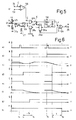
- EP
- European Patent Office
- Prior art keywords
- train
- brake
- signal
- fact
- generating
- Prior art date
- Legal status (The legal status is an assumption and is not a legal conclusion. Google has not performed a legal analysis and makes no representation as to the accuracy of the status listed.)
- Expired - Lifetime
Links
- 230000005520 electrodynamics Effects 0.000 claims abstract description 51
- 230000005284 excitation Effects 0.000 claims abstract description 8
- 230000003137 locomotive effect Effects 0.000 claims description 14
- 230000001276 controlling effect Effects 0.000 claims description 7
- 230000003247 decreasing effect Effects 0.000 claims description 5
- 230000001143 conditioned effect Effects 0.000 claims description 3
- 230000002596 correlated effect Effects 0.000 claims description 3
- 239000012530 fluid Substances 0.000 abstract 1
- 230000000875 corresponding effect Effects 0.000 description 5
- 230000001105 regulatory effect Effects 0.000 description 3
- 238000010586 diagram Methods 0.000 description 2
- 230000015556 catabolic process Effects 0.000 description 1
- 230000003750 conditioning effect Effects 0.000 description 1
Images


Classifications
-
- B—PERFORMING OPERATIONS; TRANSPORTING
- B60—VEHICLES IN GENERAL
- B60L—PROPULSION OF ELECTRICALLY-PROPELLED VEHICLES; SUPPLYING ELECTRIC POWER FOR AUXILIARY EQUIPMENT OF ELECTRICALLY-PROPELLED VEHICLES; ELECTRODYNAMIC BRAKE SYSTEMS FOR VEHICLES IN GENERAL; MAGNETIC SUSPENSION OR LEVITATION FOR VEHICLES; MONITORING OPERATING VARIABLES OF ELECTRICALLY-PROPELLED VEHICLES; ELECTRIC SAFETY DEVICES FOR ELECTRICALLY-PROPELLED VEHICLES
- B60L7/00—Electrodynamic brake systems for vehicles in general
- B60L7/24—Electrodynamic brake systems for vehicles in general with additional mechanical or electromagnetic braking
-
- B—PERFORMING OPERATIONS; TRANSPORTING
- B60—VEHICLES IN GENERAL
- B60T—VEHICLE BRAKE CONTROL SYSTEMS OR PARTS THEREOF; BRAKE CONTROL SYSTEMS OR PARTS THEREOF, IN GENERAL; ARRANGEMENT OF BRAKING ELEMENTS ON VEHICLES IN GENERAL; PORTABLE DEVICES FOR PREVENTING UNWANTED MOVEMENT OF VEHICLES; VEHICLE MODIFICATIONS TO FACILITATE COOLING OF BRAKES
- B60T13/00—Transmitting braking action from initiating means to ultimate brake actuator with power assistance or drive; Brake systems incorporating such transmitting means, e.g. air-pressure brake systems
- B60T13/10—Transmitting braking action from initiating means to ultimate brake actuator with power assistance or drive; Brake systems incorporating such transmitting means, e.g. air-pressure brake systems with fluid assistance, drive, or release
- B60T13/66—Electrical control in fluid-pressure brake systems
- B60T13/665—Electrical control in fluid-pressure brake systems the systems being specially adapted for transferring two or more command signals, e.g. railway systems
-
- B—PERFORMING OPERATIONS; TRANSPORTING
- B60—VEHICLES IN GENERAL
- B60T—VEHICLE BRAKE CONTROL SYSTEMS OR PARTS THEREOF; BRAKE CONTROL SYSTEMS OR PARTS THEREOF, IN GENERAL; ARRANGEMENT OF BRAKING ELEMENTS ON VEHICLES IN GENERAL; PORTABLE DEVICES FOR PREVENTING UNWANTED MOVEMENT OF VEHICLES; VEHICLE MODIFICATIONS TO FACILITATE COOLING OF BRAKES
- B60T15/00—Construction arrangement, or operation of valves incorporated in power brake systems and not covered by groups B60T11/00 or B60T13/00
- B60T15/02—Application and release valves
- B60T15/04—Driver's valves
- B60T15/14—Driver's valves influencing electric control means
-
- B—PERFORMING OPERATIONS; TRANSPORTING
- B60—VEHICLES IN GENERAL
- B60L—PROPULSION OF ELECTRICALLY-PROPELLED VEHICLES; SUPPLYING ELECTRIC POWER FOR AUXILIARY EQUIPMENT OF ELECTRICALLY-PROPELLED VEHICLES; ELECTRODYNAMIC BRAKE SYSTEMS FOR VEHICLES IN GENERAL; MAGNETIC SUSPENSION OR LEVITATION FOR VEHICLES; MONITORING OPERATING VARIABLES OF ELECTRICALLY-PROPELLED VEHICLES; ELECTRIC SAFETY DEVICES FOR ELECTRICALLY-PROPELLED VEHICLES
- B60L2200/00—Type of vehicles
- B60L2200/26—Rail vehicles
Definitions
- the present invention relates to a railroad train brake control system, in particular, for a train featuring a front and rear electric locomotive and a given number of cars, and designed to travel at exceptionally high speed, e.g. in the region of 300 km/hour.
- Railraod trains comprising at least one electric locomotive and a given number of cars normally feature two types of brakes, one electrodynamic and the other pneumatic (or electropneumatic), each controlled separately and independently by the crew.
- the electrodynamic type is operated by supplying the electric motors (usually two) on the locomotive with a given armature current for producing a brake torque on the motors.
- the pneumatic or electropneumatic type is operated by regulating the air pressure in the main brake line, for producing a given pressure in the brake control cylinders.
- Known brake control systems have an operating mode selector (overload, run, slow brake, fast brake, etc) and an automatic regulating device for controlling air supply and exhaust on the main line according to the selector setting.
- Said automatic regulating device comprises a relay valve; a pair of electrovalves for suppling and exhausting a control chamber on the relay valve and a pair of pressure transducers for generating electric signals proportional to the pressure inside the relay valve control chamber and main line respectively.
- control systems comprise also (for instance the ones described in Patent GB-2.036.218) an electronic central processing unit connected with a first circuit for generating a first signal depending on the electrodynamic brake efficiency and connected with a second circuit for generating a second signal related with the travelling speed.
- the electronic central processor controls the excitation of the electrovalves and the electrodynamic brakes of the train on the basis of both electrical signals produced by said pressure transducers and on the basis of said first and second signals.
- the aim of the present invention is to provide a railroad train brake control system designed to overcome the aforementioned drawback typically associated with known systems, and which also provides for a high degree of reliability and safety.
- a railroad train brake control system said train presenting at least one electric locomotive and a number of cars, and said system comprising: a pneumatic brake comprising: an air supply line; a main air line; a relay valve between said supply line and said main air line; a pair of electrovalves for respectively suppling and exhausting a relay valve control chamber ; a pair of pressure transducers for generating electric signals proportional to the air pressure in the main air line and a relay valve control chamber respectively; said system further comprising: a system operating mode selector (overload, run, slow brake, fast brake, etc) generating an electric brake control signal as function of its settings; an electrodynamic brake; first means for generating a first electric signal depending on electrodynamic braking efficiency of said electric locomotive; second means for generating a second electric signal depending on the travelling speed of said train; an electronic processing unit controlling the excitation of said electrovalves of said pneumatic brake and said electrodynamic brake on the basis of the settings of said selector, said
- Number 1 in Fig.1 indicates a railraod train conveniently consisting of a front electric locomotive 21, a rear electric locomotive 22, and a number of cars 23 (23a, 23b, ... 23n).
- Train 1 features a brake control system 2 in accordance with the present invention, and housed predominantly in the drive cabs of locomotives 21 and 22, and partly inside cars 23.
- System 2 substantially comprises: an air supply line 15 for supplying compressed air from a tank (not shown); a main air line 16 connected to a known type of distributor (not shown) controlling the brake cylinders; a selector 13 having a number of system 2 operating mode settings (isolate, overload, run, slow brake, fast brake, etc.), each corresponding to an electric reference signal generated, for example, by a potentiometer 14 assigned to selector 13; a relay valve 8 between air supply line 15 and main line 16; a pair of electrovalves 3 and 4 for respectively supplying and exhausting a relay valve 8 control chamber (not shown); a pair of pressure transducers 9 and 10 for generating electric signals proportional to the air pressure inside main line 16 and said relay valve 8 control chamber respectively; an electronic processing unit 11 for controlling excitation of electrovalves 3 and 4 controlling supply and exhaust of main line 16, on the basis of both the selector 13 setting and the electric signals generated by transducers 9 and 10.
- Processing unit 11 presents nine inputs 31-39 and six outputs 41-46.
- Inputs 31, 32 and 33 are connected respectively to the cursor of potentiometer 14 and to transducers 9 and 10.
- Inputs 34 and 35 are connected to respective blocks 24 and 25 for generating electric signals depending on the electrodynamic braking efficiency and traveling speed of train 1.
- Input 36 is connected to a transducer 26a for indicating the setting of an electrovalve 30a installed in car 23a.
- Input 37 is connected to a series of alarm contacts 27a, ... 27n installed in respective cars 23a, ... 23n.
- Inputs 38 and 39 are connected to known circuits (not shown) for supplying unit 11 with predetermined brake control signals under specific operating conditions.
- Outputs 41 and 42 are connected respectively to electrovalves 3 and 4; and outputs 43 and 44 to respective electrovalves 3a and 4a in car 23a, for supplying or exhausting compressed air from main line 16.
- Output 45 is connected to an electrovalve 30a series-connected to an emergency exhaust member 28a passenger-operated simultaneously to contact 27a, said electrovalve 30a being designed to intercept exhaust of main line 16 as described hereinafter.
- Output 46 is connected to an appropriate electrodynamic brake control device 47.
- Potentiometer 14 substantially consists of a voltage divider consisting of a central potentiometric portion 50 with a cursor, a pair of fixed positive pole resistors 51, 52, and a pair of fixed ground resistors 53, 54, so as to produce gradually decreasing voltage pickup points 55, 56, 57, 58, 59, 60.
- the cursor on portion 50 is connected to a switch terminal on switch 61, the other switch terminal being connected to pickup point 59.
- Switch 61 is controlled by an SR flip-flop 62 having the S input connected to terminal 37, and the R input to a reset network installed in the drive cab of train 1 and consisting of a positive-pole-connected push-button 63 and a grounded resistor 64.
- the common terminal of switch 61 is connected to the following inputs or terminals: the inverting input of a subtracter circuit 66 having its non-inverting input connected to terminal 56 and its output connected to the anode of diode 67; the input of a combining network 68 having three outputs 69, 70, 71 connected to respective control inputs of respective switches 72, 73, 74; the first terminal of switches 73 and 74 having a second terminal connected to the second terminal of switch 72, to the non-inverting input of comparator 75, and to the inverting input of comparator 79 via resistor 65; the first switch terminal of a controlled switch 76 having its common terminal connected to the first terminal of switch 72, and its second switch terminal connected to a common terminal of a further controlled switch 77; the inverting input of a comparator 78 having its non-inverting input connected to terminal 32 and its output connected to the R input of two SR flip-flops 83, 84; the inverting input of a subtracter circuit 80 having
- the cathode of diode 67 is grounded via resistor 87 and also connected to a switch terminal of a controlled switch 88, the other switch terminal of which is connected to the positive pole via resistor 89 and a common terminal connected to terminal 46.
- Output 71 of combining network 68 is also connected to a first input of a three-input AND circuit 90 having its second and third inputs connected respectively to terminals 36 and 39, and its output connected to the input of a NOT circuit 91, to a first input of a two-input NAND circuit 92, and to one input of a two-input NOR circuit 93 via a NOT circuit 94.
- NAND circuit 92 and NOR circuit 93 are connected to respective outputs of comparators 75, 79, the inverting and non-inverting inputs of which are connected to terminal 33.
- NAND circuit 92 and NOR circuit 93 are connected respectively to terminals 42 and 41, as described with reference to FIG.1. Said outputs are also connected to respective S inputs of flip-flops 84 and 83, the outputs of which are connected to terminals 44 and 43 in such a manner as to control electrovalves 4a or 3a in car 23a, as well as corresponding electrovalves installed in the other cars.
- NOT circuit 91 The output of NOT circuit 91 is connected to a control input of controlled switch 88.
- Amplifier 82 presents two gain conditioning inputs connected respectively to the outputs of blocks 24 and 25 for generating electric signals depending on the electrodynamic braking efficiency of train 1 (via the electric motors on locomotives 21 and 22) and on actual traveling speed.
- Block 24 substantially consists of an efficiency indicator 95 consisting of four switches, each assigned to a respective motor on locomotives 21 and 22, and which is closed or opened according to whether the motor is capable of braking electrodynamically or not; and a combining network 96 (Fig.3) for supplying output signals depending on the number of motors on locomotives 21 and 22 capable of braking electrodynamically.
- An auxiliary output of network 96 which only presents an active signal in the event of zero electrodynamic braking efficiency, is connected to a control input of switch 76.
- Block 25 substantially comprises a generator 97 for generating a signal proportional to the traveling speed of train 1; and a comparator 98 for comparing said signal with a number of reference signals and so determining within which reference speed range train 1 is traveling.
- the output of amplifier 82 is connected to the inverting input of a subtracter circuit 99 having its non-inverting input connected to terminal 57 supplying a reference voltage signal from potentiometer 14.
- amplifier 82 consists of two amplifying units having respective cascade-connected amplifiers 101, 102, each with an input resistor 103, 104 and an input-output connecting network 105, 106 consisting of a number of parallel branches, each having a resistor and a series-connected switch controlled by generator 24 or 25.
- Network 105 presents four branches with four resistors 107, 108, 109, 110 series-connected to four switches 111, 112, 113, 114, each having a control input connected to a respective output of generator 24.
- switches 111, 112, 113, 114 are closed when the number of motors capable of braking electrodynamically is 4, 3, 2 and 1 respectively.
- Network 106 presents three branches with three resistors 117, 118, 119 series-connected to three switches 121, 122, 123, each having a control input connected to a respective output of generator 25.
- switches 121, 122, 123 are closed when the traveling speed of train 1 is below 185 km/h, between 185 and 255 km/h, and over 255 km/h respectively.
- the amplifying unit comprising amplifier 101 presents a gain preferably greater than 1, whereas the one comprising amplifier 102 provides for attenuation with a gain of preferably 1 or less.
- the resistance of the resistors in network 105 is always greater than that of resistor 103, and increases in value from resisor 110 to 107.
- the resistance of the resistors in network 106 increases from resistor 119 to 117, the value of which is preferably equal to that of resistor 104.
- Fig.4 shows a graph of the air pressure inside main line 16 for different settings of selector 13 controlling potentiometer 14.
- Fig.5 shows, in detail, a possible circuit arrangement in each car 23, for catering to emergency operation of the communication cord.
- Said circuit arrangement e.g. the one in car 23a, presents a contact 27a having one terminal grounded and the opposite terminal connected to terminal 37 via the anode-cathode junction of decoupling diode 124, to the positive pole via resistor 125, and to the S input of SR flip-flop 126.
- the R input of flip-flop 126 is connected to a normal reset network substantially consisting of a grounded resistor 127 and a push-button 128 connected to the positive pole.
- the output of flip-flop 126 is connected to one input of a two-input NAND circuit 129, the other input of which is connected to the output of a voltage comparator 130 having its inverting input connected to terminal 33 and its non-inverting input 131 connected to a terminal supplying a reference voltage signal (Vr) as described in more detail later on.
- Vr reference voltage signal
- NAND circuit 129 The output of NAND circuit 129 is connected to electrovalve 30a (via NOT circuit 136), and to a delay network 132 consisting of resistor 133 and condenser 134.
- the output of network 132 and the terminal connecting position transducer 26a are connected to respective inputs of NOR circuit 135, the output of which is connected to terminal 36.
- the signal picked up at point 55 is supplied to comparators 75 and 79, which immediately disable electrovalve 4 and enable electrovalve 3 via NOR circuit 93 and electrovalves 3a, ... 3n via flip-flip 83.
- Electrovalve 3 supplies the control chamber of relay valve 8, which, in turn, raises the pressure on main line 16. Once the required pressure is reached in the chamber of relay valve 8 and main line 16, signals are generated by respective transducers 10 and 9 for disabling excitation of electrovalve 3 and electrovalves 3a,...3n via comparator 78 and flip-flop 83.
- potentiometer 14 The signal picked up at point 55 by potentiometer 14 is actually added to a ramp signal generated by an appropriate circuit (not shown) which, being of known performance, is not described herein for the sake of simplicity.
- potentiometer 14 is set to pickup point 56, thus producing a slightly lower voltage level and, consequently, a lower pressure (e.g. 5 bar) in main line 16.
- the signal picked up by potentiometer 14 corresponds to the center portion 50 cursor setting, which signal provides for closing switch 72 by virtue of output 69 of comparing network 68 switching to 0, and for opening switches 73 and 74 by virtue of outputs 70 and 71 of network 68 being set to 1.
- the pneumatic-only air pressure on main line 16 is as shown by the continuous line in Fig.4a, and ranges from a maximum of 4.5 bar, corresponding substantially to application of the brake blocks, to a minimum of 3.5 bar, corresponding to maximum pneumatic-only service braking when selector 13 is turned 104° in relation to the initial brake setting.
- subtracter circuit 99 supplies an electric output signal corresponding, in the case of a 0 signal at the output of subtracter circuit 80, to the signal at terminal 57, thus resulting solely in application of the brake blocks (4.5 bar pressure in main line 16).
- subtracter circuit 99 supplies an output signal equal to the difference between the previous signal and the contribution of said positive signal amplified on the basis of electrodynamic braking efficiency and the traveling speed of train 1, as already stated.
- the air pressure in main line 16 is therefore as shown in Fig.4a, wherein lines 4M, 3M, 2M and 1M show air pressure performance depending on whether electrodynamic braking is provided for by four, three, two or one motor respectively, and assuming, in all four cases, a traveling speed of below 185 km/h.
- the Fig.4b graph shows air pressure performance in main line 16 assuming electrodynamic braking is provided for by two motors, with respective traveling speeds of >255, 185-255 and ⁇ 185 km/h.
- the fast brake function is performed by setting the cursor of potentiometer 14 to pickup point 60 (Fig.2). This substantially results in a particularly low amplitude signal being supplied to the input of comparison network 68, which supplies a 0 signal at output 71 and positive signals at outputs 69 and 70 for closing switch 74 and opening switches 72 and 73.
- the 0 signal at the output of network 68 also zeroes the output of AND circuit 90, which, via NOT circuit 91, activates switch 88, thus producing a maximum control signal on device 47 and, consequently, maximum electro-dynamic braking force. Moreover, the 0 signal at the output of AND circuit 90 switches the output of NAND circuit 92 to 1, thus energizing electrovalve 4 and also electrovalves 4a,...4n via flip-flop 84.
- system 2 is designed to prevent the train being stopped by a passenger operating the communication cord, which function is performed exclusively by the crew on the basis of appropriate emergency alarms and indicators. Provision is made, however, for stopping the train in the event of a breakdown on system 2.
- contact 27a is temporarily and immediately broken (instant t0 in Fig.6), and main line 16 exhausted via exhaust member 28a and de-energized normally-open electrovalve 30a.
- Flip-flop 62 immediately activates switch 61 for achieving maximum service braking as already described; which condition may be reset by the crew simply pressing button 63, for preventing the train from being stopped on viaducts or inside tunnels, etc.
- the output of flip-flop 126 maintains a logic level 1 at one of the two inputs of NAND circuit 129, the other input of which switches from 0 to 1 the instant (t1 in Fig.6) the pressure detected by transducer 10 causes this to generate an electric signal lower than the Vr reference signal at the non-inverting input of comparator 130 in Fig.5.
- Simultaneous logic level 1 signals at the inputs of NAND circuit 129 energize (instant t2) electrovalve 30a, which, within a given operating time, intercepts exhaust of main air line 16.
- system 2 is extremely safe and reliable under all operating conditions, by enabling automatic arrest of train 1 in the event of malfunctioning of any of the electronic control circuits on the system.
Landscapes
- Engineering & Computer Science (AREA)
- Transportation (AREA)
- Mechanical Engineering (AREA)
- Physics & Mathematics (AREA)
- Electromagnetism (AREA)
- Power Engineering (AREA)
- Braking Systems And Boosters (AREA)
- Electric Propulsion And Braking For Vehicles (AREA)
- Train Traffic Observation, Control, And Security (AREA)
Claims (17)
- Bremssteuerungsvorrichtung für einen Zug einer Eisenbahn, wobei dieser Zug (1) mindestens eine elektrische Lokomotive (21, 22) und eine Anzahl von Waggons aufweist und diese Vorrichtung umfaßt:
eine pneumatische Bremse mit:
einer Luftzuführungsleitung (15),
einer Hauptluftleitung (16),
einem Führungsventil (8) zwischen der Luftzuführungsleitung (15) und der Hauptluftleitung (16),
einem Paar von Elektroventilen (3, 4) zur jeweiligen Befüllung und Entleerung einer Kontrollkammer des Führungsventils (8),
einem Paar von Druckübertragern (9, 10) zur Erzeugung von elektrischen Signalen, die jeweils proportional zum Luftdruck in der Hauptluftleitung (16) bzw. zum Luftdruck in der Kontrollkammer des Führungsventils (8) sind,
wobei diese Vorrichtung weiter aufweist:
eine Betriebszustandauswahleinrichtung (13) (Überlast, Fahrt, langsames Bremsen, schnelles Bremsen, etc), die ein elektrisches Bremssteuersignal als Funktion ihrer Einstellung generiert,
eine elektrodynamische Bremse (47),
erste Mittel (24) zur Erzeugung eines ersten elektrischen Signals, das von dem Wirkungsgrad des elektrodynamischen Bremsens der genannten elektrischen Lokomotive (21, 22) abhängt,
zweite Mittel (25) zur Erzeugung eines zweiten elektrischen Signals, das von der Reisegeschwindigkeit des genannten Zuges (1) abhängt,
eine elektronische Steuereinheit (11), welche das Ansprechen der besagten Elektroventile (3, 4) der pneumatischen Bremse und der elektrodynamischen Bremse (47) auf der Basis der Stellung der besagten Zustandsauswahleinrichtung (13), der ersten und zweiten Signale und der besagten elektrischen Signale, die von den Übertragern (9, 10) geliefert werden, steuert,
dadurch gekennzeichnet, daß die elektronische Steuereinheit (11) erste Schaltmittel (76) umfaßt, die von dem ersten Signal gesteuert werden und dazu vorgesehen sind, im Fall eines Wirkungsgrades Null des elektrodynamischen Bremsens (oder bei dem Wert eines Wirkungsgrades unterhalb eines vorgegebenen Schwellwertes) eine erste Arbeitsposition, bei der das elektrische Signal der Zustandsauswahleinrichtung direkt aufgenommen wird, oder eine zweite Arbeitsposition einzunehmen, bei der im Falle eines Wirkungsgrades ungleich Null für das elektrodynamische Bremsen das Signal der Zustandsauswahleinrichtung (13) dritten Mitteln (82) zugeleitet wird, die ein Ausgangssteuersignal für die pneumatische Bremse liefern,
wobei die dritten Mittel (82) von den ersten (24) und den zweiten (25) Mitteln in einer solchen Weise gesteuert werden, wenn der Zug bereits der maximalen elektrodynamischen Bremskraft unterliegt, um den Anteil des pneumatischen Bremsens bei steigender Geschwindigkeit des Zuges (1) und bei sich verminderndem pneumatischen Bremsanteil bei gesteigertem Wirkungsgrad des elektrodynamischen Bremsens, der mit der Anzahl der zum elektrodynamischen Bremsen geeigneten Motoren korreliert ist, zu vermindern. - Vorrichtung nach Anspruch 1, dadurch gekennzeichnet, daß sie erste Subtraktionsmittel (80) zum Vergleich des elektrischen Signals, das von der Zustandsauswahleinrichtung (13) erzeugt wird, mit einem Referenzsignal umfaßt, wobei die dritten Mittel (82) eine Eingangsverstärkereinheit umfassen, die mit dem ersten Subtraktionsmittel verbunden ist und eine Verstärkung aufweist, die von den ersten und zweiten Signalen gesteuert wird.
- Vorrichtung nach Anspruch 2, dadurch gekennzeichnet, daß der Verstärkungsfaktor in einer solchen Weise einstellbar ist, um größer als Eins, gleich Eins oder kleiner als Eins zu sein.
- Vorrichtung nach einem der Ansprüche 2 oder 3, dadurch gekennzeichnet, daß die ersten signalerzeugenden Mittel (24) im wesentlichen Mittel (95) zur Erfassung des Wirkungsgrades des elektrodynamischen Bremsens der Motoren des Zuges (1) und ein verbindendes Netzwerk (96) umfassen, welches mit den jeweiligen Ausgängen der Erfassungsmittel (95) verbunden ist, um Steuersignale zu erzeugen, die der elektronischen Steuereinheit (11) zugeführt werden und die mit der Anzahl der zum elektrodynamischen Bremsen geeigneten Motoren korreliert sind.
- Vorrichtung nach einem der vorstehenden Ansprüche 2 bis 4, dadurch gekennzeichnet, daß die zweiten signalerzeugenden Mittel (25) im wesentlichen Mittel (97) zur Erfassung der Reisegeschwindigkeit des Zuges (1) und ein vergleichendes Netzwerk (98) umfassen, welches mit den Erfassungsmitteln (97) verbunden ist, um eine Anzahl Von Steuersignalen zu erzeugen, wobei jedes einem vorgegebenen Geschwindigkeitsbereich des Zuges (1) zugewiesen ist.
- Vorrichtung nach einem der vorstehenden Ansprüche 2 bis 5, dadurch gekennzeichnet, daß die Verstärkereinheit (82) eine erste und eine zweite in Kaskade geschaltete Verstärkerschaltung aufweist, von denen die Verstärkung jeweils durch die ersten (24) bzw. zweiten (25) signalerzeugenden Mittel vorgebeben werden.
- Vorrichtung nach Anspruch 6, dadurch gekennzeichnet, daß die erste Verstärkungsschaltung einen ersten Verstärker (101) umfaßt, der über ein erstes verstärkungsgesteuertes Netzwerk (105) verfügt, welches von den ersten signalerzeugenden Mitteln (24) angesteuert wird.
- Vorrichtung nach einem der vorstehenden Ansprüche 6 oder 7, dadurch gekennzeichnet, daß die zweite Verstärkungsschaltung einen zweiten Verstärker (102) umfaßt, der über ein zweites verstärkungsgesteuertes Netzwerk (106) verfügt, welches von den zweiten signalerzeugenden Mitteln (25) angesteuert wird.
- Vorrichtung nach einem der vorstehenden Ansprüche 2 bis 8, dadurch gekennzeichnet, daß sie über zweite Subtraktionsmittel (99) verfügt, um ein von der Verstärkereinheit (82) erzeugtes Signal aufzunehmen und um ein Differenzsignal zu erzeugen, welches im wesentlichen dem ersten Schaltmittel (76) zugeführt wird, wobei das Differenzsignal dadurch erzeugt wird, daß das von der Verstärkereinheit (82) erzeugte Signal von einem vorbestimmten Referenzsignal abgezogen wird, welches in geeigneter Weise an einem Punkt (57) abgenommen wird, der über die Zustandsauswahleinrichtung (13) auswählbar ist.
- Vorrichtung nach einem der vorstehenden Ansprüche, dadurch gekennzeichnet, daß sie ein Anzahl von Paaren von Elektroventilen zum Entleeren (3a, ... 3n) und zum Befüllen (4a, ... 4n) der Hauptluftleitung (16) umfaßt, wobei jedes Paar entsprechend in einem Waggon (23a, ... 23n) des Zuges (1) eingebaut ist und von der elektronischen Steuereinheit (11) gesteuert wird.
- Vorrichtung nach einem der vorstehenden Ansprüche, bei der jeder Waggon (23a, ... 23n) des Zuges (1) mindestens über einen ein Alarmsignal auslösenden Kontakt (27a, ... 27n) und über ein ein schnelles Entleeren gestattendes Element (28a, ... 28n) verfügt, um die Hauptluftleitung (16) zu entleeren, dadurch gekennzeichnet, daß sie für jeden Waggon (23a, ... 23n) über ein Elektroventil (30a, ... 30n) verfügt, um die über das ein schnelles Entleeren gestattende Element (28a, ... 28n) entweichende Luft aufzufangen.
- Vorrichtung nach Anspruch 11, dadurch gekennzeichnet, daß sie über zweite Schaltmittel (61) zwischen der Zustandsauswahleinrichtung (13) und dem ersten Schaltmittel (76) verfügt, wobei die zweiten Schaltmittel (61) so ausgestaltet sind, um eine erste Betriebsposition, bei der die Zustandsauswahleinrichtung (13) mit dem ersten Schaltmittel (76) verbunden ist, und eine zweite Betriebsposition einzunehmen, bei der die ersten Schaltmittel (76) mit einem Punkt (60) verbunden sind, der eine Aufnahme eines vorbestimmten Signals der Zustandsauswahleinrichtung (13) gestattet und eine maximale Bremsung des Zuges (1) einleitet, wobei jeder auslösende Kontakt (27a, ... 27n), sofern er geschaltet wird, die zweiten Schaltmittel (61) von der ersten zur zweiten Betriebsposition umschaltet.
- Vorrichtung nach Anspruch 12, dadurch gekennzeichnet, daß sie von der Besatzung des Zuges zu schaltende Mittel (62, 63, 64) umfaßt, um die erste Betriebsposition der zweiten Schaltmittel (61) zurückzusetzen, falls die besagten zweiten Schaltmittel (61) durch die auslösenden Kontakte (27a, ... 27n) in die zweite Betriebsposition gesetzt worden sind.
- Vorrichtung nach einem der vorstehenden Ansprüche 11 bis 13, dadurch gekennzeichnet, daß sie Mittel (126, 130, 129) umfaßt, um die genannten Elektroventile (30a, ... 30n) auszulösen, die dazu vorgesehen sind, die die über das ein schnelle Entleeren gestattende Element (28a, ... 28n) entweichende Luft aufzufangen, wobei diese Auslösemittel weiterhin Mittel (130) zur Bestätigung des Abfallens des Luftdruckes innerhalb der Kontrollkommer des Führungsventils (8) umfassen.
- Vorrichtung nach einem der vorstehenden Ansprüche 11 bis 14, dadurch gekennzeichnet, daß jedes Elektroventil (3a, ... 3n) einen Positionsübersetzer (26a, ... 26n) aufweist, um ein drittes und ein viertes Signal zu erzeugen, je nachdem, ob ein Betätigungselement des Elektroventils (30a, ... 30n) auf die erste oder auf die zweite Betriebsposition gesetzt ist.
- Vorrichtung nach Anspruch 15, dadurch gekennzeichnet, daß sie Mittel (135, 86, 85, 88, 47) zur Erlangung eines maximalen elektrodynamischen Bremsens oder einer Schnellbremsung des Zuges (1) umlaßt, wobei diese Mittel jeweils von jedem der Positionsübersetzer (26a, ... 26n) angesteuert werden.
- Vorrichtung nach einem der vorstehenden Ansprüche, dadurch gekennzeichnet, daß Schnellbremsmittel (60, 68, 74, 88, 90, 92, 84, 47) vorgesehen sind, um ein schnellstmögliches Abbremsen des Zuges zu erreichen, wobei diese Schnellbremsmittel (60, 68, 74, 88, 90, 92, 84, 47) eine maximale elektrodynamische Bremskraft erzeugen und die Anregung der Ausstoß-Elektroventile (4, 4a, ... 4n) der Lokomotive (21, 22) und der Waggons (23a, ... 23n) gewährleisten, und daß die Schnellbremsmittel (60, 68, 74, 88, 90, 92, 84, 47) weiterhin das Öffnen eines großen Durchlasses in der Hauptluftleitung (16) bewirken.
Applications Claiming Priority (2)
| Application Number | Priority Date | Filing Date | Title |
|---|---|---|---|
| IT8768118A IT1211623B (it) | 1987-12-23 | 1987-12-23 | Sistema di comando e di controllodella frenatura di un convoglio ferroviario |
| IT6811887 | 1987-12-23 |
Publications (3)
| Publication Number | Publication Date |
|---|---|
| EP0321987A2 EP0321987A2 (de) | 1989-06-28 |
| EP0321987A3 EP0321987A3 (en) | 1990-12-19 |
| EP0321987B1 true EP0321987B1 (de) | 1995-03-15 |
Family
ID=11307976
Family Applications (1)
| Application Number | Title | Priority Date | Filing Date |
|---|---|---|---|
| EP88121533A Expired - Lifetime EP0321987B1 (de) | 1987-12-23 | 1988-12-22 | Eisenbahnbremsregelsystem |
Country Status (6)
| Country | Link |
|---|---|
| EP (1) | EP0321987B1 (de) |
| AT (1) | ATE119835T1 (de) |
| DE (1) | DE3853350T2 (de) |
| ES (1) | ES2072259T3 (de) |
| IT (1) | IT1211623B (de) |
| PT (1) | PT89334B (de) |
Families Citing this family (3)
| Publication number | Priority date | Publication date | Assignee | Title |
|---|---|---|---|---|
| TWI279338B (en) * | 2002-04-18 | 2007-04-21 | Siemens Ag | Method to electro-dynamically brake a track-vehicle |
| FR3064965B1 (fr) * | 2017-04-10 | 2019-04-05 | Matisa Materiel Industriel S.A. | Robinet de mecanicien simplifie et circuit pneumatique de freinage d’une rame ferroviaire incorporant un tel robinet de mecanicien |
| CN115214583B (zh) * | 2022-07-26 | 2023-09-22 | 眉山中车制动科技股份有限公司 | 一种铁路货车电空制动阀的控制系统 |
Family Cites Families (2)
| Publication number | Priority date | Publication date | Assignee | Title |
|---|---|---|---|---|
| US3528709A (en) * | 1968-09-23 | 1970-09-15 | Gen Signal Corp | Electric current-to-pneumatic pressure transducer |
| US4225813A (en) * | 1978-11-28 | 1980-09-30 | Westinghouse Electric Corp. | Transit vehicle dynamic brake control apparatus |
-
1987
- 1987-12-23 IT IT8768118A patent/IT1211623B/it active
-
1988
- 1988-12-22 ES ES88121533T patent/ES2072259T3/es not_active Expired - Lifetime
- 1988-12-22 DE DE3853350T patent/DE3853350T2/de not_active Expired - Fee Related
- 1988-12-22 EP EP88121533A patent/EP0321987B1/de not_active Expired - Lifetime
- 1988-12-22 AT AT88121533T patent/ATE119835T1/de not_active IP Right Cessation
- 1988-12-23 PT PT89334A patent/PT89334B/pt not_active IP Right Cessation
Also Published As
| Publication number | Publication date |
|---|---|
| PT89334A (pt) | 1989-09-14 |
| ATE119835T1 (de) | 1995-04-15 |
| EP0321987A3 (en) | 1990-12-19 |
| DE3853350T2 (de) | 1996-01-04 |
| EP0321987A2 (de) | 1989-06-28 |
| IT8768118A0 (it) | 1987-12-23 |
| DE3853350D1 (de) | 1995-04-20 |
| ES2072259T3 (es) | 1995-07-16 |
| IT1211623B (it) | 1989-11-03 |
| PT89334B (pt) | 1993-12-31 |
Similar Documents
| Publication | Publication Date | Title |
|---|---|---|
| US5738311A (en) | Distributed power train separation detection | |
| US5412572A (en) | Computer controlled railway brake equipment | |
| US4616881A (en) | Tractor-trailer brake system including a trailer brake control valve | |
| US5813635A (en) | Train separation detection | |
| US3920280A (en) | Antiskid brake control system having malfunction protection | |
| US8774990B2 (en) | Method for demanding safety reactions for a rail vehicle | |
| US5249125A (en) | Computer controlled railway brake equipment | |
| US3799623A (en) | Controlling railway vehicle brakes | |
| US4316640A (en) | Electro pneumatic brake system for railway car | |
| EP0630788B1 (de) | Elektronisches Bremssystem mit Prüfungssystem | |
| KR20220170460A (ko) | 차량용 제동장치 | |
| GB2158901A (en) | Brake system for automotive vehicles | |
| US4494199A (en) | Brake system, especially for a motor vehicle | |
| EP0321987A2 (de) | Eisenbahnbremsregelsystem | |
| JP2852549B2 (ja) | 多回路制動装置を制御する方法及び装置 | |
| GB2162265A (en) | Braking pressure generator for slip-controlled brake systems | |
| US2719911A (en) | Train speed control system | |
| CA1223621A (en) | Electric train line brake control system | |
| EP1316489B1 (de) | Sicherheitssystem zum kontinuierlichen Kontrollieren der Integrität eines Schienenfahrzeuges | |
| GB1401581A (en) | Antiwheel locking control systems | |
| US4083608A (en) | Air compressor lay-over control circuit | |
| US6127747A (en) | Method and apparatus for detecting leakage current on a two wire DC or AC power line | |
| EP0335532B1 (de) | Elektropneumatisches Bremssystem | |
| US2322022A (en) | Control device | |
| US6474149B1 (en) | Method and apparatus for detecting a defective pressure switch |
Legal Events
| Date | Code | Title | Description |
|---|---|---|---|
| PUAI | Public reference made under article 153(3) epc to a published international application that has entered the european phase |
Free format text: ORIGINAL CODE: 0009012 |
|
| AK | Designated contracting states |
Kind code of ref document: A2 Designated state(s): AT BE CH DE ES FR GB LI |
|
| PUAL | Search report despatched |
Free format text: ORIGINAL CODE: 0009013 |
|
| AK | Designated contracting states |
Kind code of ref document: A3 Designated state(s): AT BE CH DE ES FR GB LI |
|
| 17P | Request for examination filed |
Effective date: 19910522 |
|
| 17Q | First examination report despatched |
Effective date: 19921209 |
|
| GRAA | (expected) grant |
Free format text: ORIGINAL CODE: 0009210 |
|
| AK | Designated contracting states |
Kind code of ref document: B1 Designated state(s): AT BE CH DE ES FR GB LI |
|
| REF | Corresponds to: |
Ref document number: 119835 Country of ref document: AT Date of ref document: 19950415 Kind code of ref document: T |
|
| REF | Corresponds to: |
Ref document number: 3853350 Country of ref document: DE Date of ref document: 19950420 |
|
| REG | Reference to a national code |
Ref country code: CH Ref legal event code: PFA Free format text: SAB WABCO S.P.A. |
|
| ET | Fr: translation filed | ||
| RAP4 | Party data changed (patent owner data changed or rights of a patent transferred) |
Owner name: SAB WABCO S.P.A. |
|
| REG | Reference to a national code |
Ref country code: ES Ref legal event code: FG2A Ref document number: 2072259 Country of ref document: ES Kind code of ref document: T3 |
|
| REG | Reference to a national code |
Ref country code: FR Ref legal event code: CD |
|
| PG25 | Lapsed in a contracting state [announced via postgrant information from national office to epo] |
Ref country code: AT Effective date: 19951222 |
|
| BECN | Be: change of holder's name |
Effective date: 19950315 |
|
| PG25 | Lapsed in a contracting state [announced via postgrant information from national office to epo] |
Ref country code: BE Effective date: 19951231 |
|
| PLBE | No opposition filed within time limit |
Free format text: ORIGINAL CODE: 0009261 |
|
| STAA | Information on the status of an ep patent application or granted ep patent |
Free format text: STATUS: NO OPPOSITION FILED WITHIN TIME LIMIT |
|
| 26N | No opposition filed | ||
| BERE | Be: lapsed |
Owner name: SAB WABCO S.P.A. Effective date: 19951231 |
|
| PGFP | Annual fee paid to national office [announced via postgrant information from national office to epo] |
Ref country code: CH Payment date: 19961129 Year of fee payment: 9 |
|
| PG25 | Lapsed in a contracting state [announced via postgrant information from national office to epo] |
Ref country code: LI Free format text: LAPSE BECAUSE OF NON-PAYMENT OF DUE FEES Effective date: 19971231 Ref country code: CH Free format text: LAPSE BECAUSE OF NON-PAYMENT OF DUE FEES Effective date: 19971231 |
|
| REG | Reference to a national code |
Ref country code: CH Ref legal event code: PL |
|
| PGFP | Annual fee paid to national office [announced via postgrant information from national office to epo] |
Ref country code: GB Payment date: 19981210 Year of fee payment: 11 |
|
| PGFP | Annual fee paid to national office [announced via postgrant information from national office to epo] |
Ref country code: ES Payment date: 19981216 Year of fee payment: 11 |
|
| PG25 | Lapsed in a contracting state [announced via postgrant information from national office to epo] |
Ref country code: GB Free format text: LAPSE BECAUSE OF NON-PAYMENT OF DUE FEES Effective date: 19991222 |
|
| GBPC | Gb: european patent ceased through non-payment of renewal fee |
Effective date: 19991222 |
|
| PGFP | Annual fee paid to national office [announced via postgrant information from national office to epo] |
Ref country code: FR Payment date: 20001128 Year of fee payment: 13 |
|
| PGFP | Annual fee paid to national office [announced via postgrant information from national office to epo] |
Ref country code: DE Payment date: 20001220 Year of fee payment: 13 |
|
| PG25 | Lapsed in a contracting state [announced via postgrant information from national office to epo] |
Ref country code: ES Free format text: LAPSE BECAUSE OF NON-PAYMENT OF DUE FEES Effective date: 20001223 |
|
| PG25 | Lapsed in a contracting state [announced via postgrant information from national office to epo] |
Ref country code: DE Free format text: LAPSE BECAUSE OF NON-PAYMENT OF DUE FEES Effective date: 20020702 |
|
| PG25 | Lapsed in a contracting state [announced via postgrant information from national office to epo] |
Ref country code: FR Free format text: LAPSE BECAUSE OF NON-PAYMENT OF DUE FEES Effective date: 20020830 |
|
| REG | Reference to a national code |
Ref country code: FR Ref legal event code: ST |
|
| REG | Reference to a national code |
Ref country code: ES Ref legal event code: FD2A Effective date: 20010113 |