EP0321983A2 - Method for processing color image and apparatus therefor - Google Patents
Method for processing color image and apparatus therefor Download PDFInfo
- Publication number
- EP0321983A2 EP0321983A2 EP88121523A EP88121523A EP0321983A2 EP 0321983 A2 EP0321983 A2 EP 0321983A2 EP 88121523 A EP88121523 A EP 88121523A EP 88121523 A EP88121523 A EP 88121523A EP 0321983 A2 EP0321983 A2 EP 0321983A2
- Authority
- EP
- European Patent Office
- Prior art keywords
- color
- image
- copy
- lookup table
- original image
- Prior art date
- Legal status (The legal status is an assumption and is not a legal conclusion. Google has not performed a legal analysis and makes no representation as to the accuracy of the status listed.)
- Granted
Links
Images


Classifications
-
- H—ELECTRICITY
- H04—ELECTRIC COMMUNICATION TECHNIQUE
- H04N—PICTORIAL COMMUNICATION, e.g. TELEVISION
- H04N1/00—Scanning, transmission or reproduction of documents or the like, e.g. facsimile transmission; Details thereof
- H04N1/46—Colour picture communication systems
- H04N1/56—Processing of colour picture signals
- H04N1/60—Colour correction or control
- H04N1/6016—Conversion to subtractive colour signals
- H04N1/6019—Conversion to subtractive colour signals using look-up tables
-
- H—ELECTRICITY
- H04—ELECTRIC COMMUNICATION TECHNIQUE
- H04N—PICTORIAL COMMUNICATION, e.g. TELEVISION
- H04N1/00—Scanning, transmission or reproduction of documents or the like, e.g. facsimile transmission; Details thereof
- H04N1/46—Colour picture communication systems
- H04N1/56—Processing of colour picture signals
- H04N1/60—Colour correction or control
- H04N1/6058—Reduction of colour to a range of reproducible colours, e.g. to ink- reproducible colour gamut
Definitions
- This invention relates to a method for processing a color image and an apparatus therefor, particularly to a method of color image processing for converting color original image data into desired color copy image data and an apparatus therefor.
- this invention relates to a color image processing method for faithfully reproducing the color image of an input color original image in the form of a color copy image and to a color image processing apparatus for executing the color image processing method by the use of a small memory region.
- color image processing apparatuses for performing the operation of producing color copy images on recording media based on input color original image data have begun to disseminate in various fields.
- the color image processing apparatuses are utilized as ink jet printers, for example. because of the high excellence in color reproducibility, they find unity mainly in applications specializing in designs of apparels and room interiors, namely the applications which demand faithful color reproduction of original images.
- 4,758,885 effects faithful reproduction of the color image of an original image on a copy image where the range of color reproduction of the color image signal in the input system is wider than that of color reproduction in the output system by causing the input color image to be copied with the range of color reproduction in the input system compressed to that in the output system.
- This technique compared with the conventional technique which gives no correction of any sort to the input color image signal, permits reproduction of a copy image rich in gradation.
- Japanese Patent Application Disclosure SHO 59(1984)-123.390 teaches a technique which comprises preparing a lookup table storing data necessary for the processing, retreaving pertinent data from the lookup table, and enabling the processing to be speedily carried out based on the output data.
- this technique relies solely on the provision of this lookup table.
- the lookup table is inevitably required to possess a very large capacity such as to jeopardize the economy of the technique itself. To reduce the volume of data stored in one lookup table.
- the technique is compelled to make use of a plurality of such lookup tables.
- a particular lookup table suitable for the quality of the input color image signal is automatically selected from the plurality of lookup tables and an image of ample legibility is formed based on the contents of the selected lookup table.
- An effort to represent an original image in multi-gradation results in a colossal addition to the volume of data to be stored in the lookup table for the correction of multi-gradation images and calls for provision of a large memory region.
- This invention aims to provide a method of color image processing free from the various drawbacks suffered by the prior art as described above and an apparatus for working the method.
- One object of this invention is to provide a method of color image processing for producing a copy image faithfully reproducing the color image of a given original image.
- Another object of this invention is to provide a color image processing apparatus which permits the user to store therein the corrective functions to be used for the formation of lookup tables, call out thereof a corrective function pertinent to the occasion, and consult the lookup table formed based on the retrieved corrective function, requires the memory region thereof to permit storage of the formed loodup tables and not to be so large as to store a plurality of lookup tables independently of one another even when a correction is to be given to a multigradation image or when some other lookup table is to be prepared to suit the prevailing status of the input system, for example, and which consequently allows a saving in the memory region.
- Fig. 1 A and Fig. 1B typically illustrate the range of color reproduction of an original image with the CRT display and the range of color reproduction with the ink jet printer, as plotted respectively in the a *- b" coordinates system and the a *- L' coordinates system.
- the range of color reproduction of an original image which can be reproduced by the CRT display is wider than the range of color reproduction of a copy image which can be reproduced by the ink jet printer.
- the range of color reproduction of the original image must be made to conform with the range of color reproduction of the copy image.
- the present invention therefore, contempaltes effecting this conformation by fulfilling conformation of the white point and the chromatic axis between the originally image and the copy image.
- the contents to be stored in the lookup table which is required in attaining this conformation are adapted to be formed at a desired time based on the corrective function to be selected, the memory capacity for the lookup table can be reduced to the fullet possible extent.
- the present invention aims to permit a saving in the memory region.
- an ink jet printer which is adapted to print out a copy image based on input image data will be illustrated. It is assumed that this ink jet printer is adapted so that an original image exhibited on the color CRT display, one of the component members of a computer graphic apparatus (hereinafter referred to as "CG device" for smort), is transferred thereto.
- CG device computer graphic apparatus
- Fig. 2 illustrates the construction of peripheral devices for an image processing apparatus an one embodiment of the present invention.
- an ink jet printer 7 is connected through the medium of a connecting cable adapted for transfer of image signals and control signals to a CG device 1 which is composed of a color CRT display 2, a keyboard 3, a table 4, a controller 5, etc.
- This ink jet printer 7 is provided with a mode select switch 8 which forms part of command means to be described later on and a print switch 9 not shown) which is disposed on an operation panel 9 and used in selecting a print start.
- an original image a color image to be exhibited on the color CRT display, a component member of the CG device.
- This invention is not required to be limited to this particular color image.
- a copy image a color image to be printed out from the ink jet printer.
- This invention is not required to be limited to this particular copy image. It is of course permissible to use as a copy image the image represented by a YMC signal such as, for example, a color image to be printed out by a thermographic or electrostatic printer.
- Fig. 3 illustrates a color image signal processing circuit disposed inside the ink jet printer.
- a frame memory 10 disposed inside the ink jet printer is connected through the medium of a connecting cable 6 and a proper interface (not shown) to the CG device 1.
- This frame memory 10 is adapted to store therein the RGB signal transmitted from the CG device 1 and intended to exhibit an original image on the color CRT display 2.
- RGB signal refers to the signal serving to convey each of the three primary colors, red (R), green (G), and blue (B), in the additive color blend.
- the color CRT display 2 is so adapted as to represent virtually all of the colors by effecting the additive color blend through suitable adjustment of the intensity of each of the red (R), green (G), and blue (B) colors.
- a lookup table memory 12 which forms part of table forming means is connected through a RGB bus 11 for the transfer of RGB signals to the frame memory 10.
- This lookup table memory 12 is adapted so that the lookup table stored therein lends itself to the conversion of the RGB signal adapted for the color CRT display 2 into the YMC signal adapted for the ink jet printer 7.
- YMC signal refers to the signal serving to convey each of the three primary colors, yellow (Y), magenta (M), and cyan (C), in the reductive color blend.
- the ink jet printer 7 is so adapted as to represent virtually all of the colors by effecting the reductive color blend through suitable adjustment of the intensity of each of the yellow (Y), magenta (M), and cyan (C) colors.
- a line buffer memory 14 for storing one line full of color image data represented by the YMC signals is connected to the lookup table memory 12 through the medium of a YMC bus 13 for the transfer of YMC signals which have undergone convertion in the memory 12.
- a print mechanism 15 serving to form a color image on a recording paper based on color image data fed in through the YMC bus 13 is connected to the line buffer memory 14.
- the lookup table memory 12 is connected to a computer 18 having connected thereto a multiplexer 17 which has a mode select switch 8 and a plurality of coefficient series 16 as means for memorizing corrective functions connected thereto and constitutes itself part of command mans serving to select one coefficient series from the plurality of coefficient series 16 in accordance with the setting of the mode select switch 8.
- a computer 18 is formed a lookup table for the conversion of original image data into copy image data based on the coefficient series selected as described above.
- the lookup table thus formed in the computer 18 is transferred to the lookup table memory 12 and stored therein.
- the computer 18 forms part of the table forming means.
- the computer 18 is depicted as connected to the multiplexer 17 having the plurality of coefficient series connected thereto. One coefficient series may suffice. Then, the multiplexer 17 may be omitted.
- the control means inside the ink jet printer 7 is initialized (Si ) and readied to start. It is assumed that an original image transferred from the CG device 1 is exhibited on the color CRT display 2 and this original image is in a state ready to be transferred, as occasion demands, to the ink jet printer 7. It is also assumed that the mode select switch 8 is set at a proper position.
- the control device judges whether or not the print switch is set on or not (S2). This judgment at S2 is repeated until the print switch is turned on.
- the control device executes a command for the original image data to be issued from the CG device and admitted in the form of a RGB signal into the frame memory 10 via the connecting cable 6 (S3) and stored sequentially at a prescribed address in the frame memory 10.
- the admission of the original image data in the frame memory 10 may be effected before the print switch is turned on.
- control device executes a command for a particular coefficient series 16 selected by the setting of the mode select switch 8 to be transferred via the multiplexer 17 to the computer 18. Further, the control device reads a pertinent corrective function out of the corrective function 16 and the original image data out of the frame memory 10 and then executes a command for the computer 18 to form a lookup table addressed to the original image data, based on the corrective function (S4).
- the lookup table formed in the computer 18 is stored at a prescribed address on the lookup table memory 12. Since a lookup table is formed improvisatorially each time the print switch is turned on, a saving is attained in the memory region which is required where a plurality of lookup tables are to be stored so as to cope with various states.
- the apparatus When the lookup table is admitted in and allocated to the prescribed address in the lookup table memory 12, the apparatus is ready for the conversion of the original image into a copy image.
- the color of the original image exhibited on the color CRT display 2 is represented as (XYZ) CRT by a (XYZ) color system and transferred from the CG device 1 to the color CRT display.
- the color represented by the RGB signal is represented as (RGB) CRT by the (RGB) color system
- the relation between the two colors is defined by the Formula 1 as widely known.
- the symbol "f" used in the Formula 1 denotes a proper function representing the characteristic of the color CRT display 2.
- this function ⁇ is, therefore, determined by a procedure which comprises extracting a suitable number, N, of representative colors from the ranges of color reproduction respectively of original image and copy image by the use of the (L*a*b*) color system as a uniform perceptive color space, performing on these representative colors an airthmetic operation such as for the conformation of the white color and the conformation of the achromatic axis, and subjecting the representative colors as arithmetically processed to approximation by the least squares method thereby minimizing the color difference between the original image and the copy image.
- L a * , and b * are calculated by the Formula 5, i.e. equations for the conversion of the knwon (XYZ) color system to the (L * a * b * ) color system.
- the symbols X, Y, and Z used in the equations represent three values of stimulus of the standard light source or standard color to be used for the illumination.
- N a suitable number, of the following representative colors corresponding to the ranges of color reproduction of the original image and the copy image are extracted by the use of the (L*a*b*) color system.
- bi*) CRT (Li*. ai*, bi*) COPY (Formula) (wherein i 1,2,7-8j, ....,N ).
- i 1,2,7-8, ....,N .
- (Jj*, aj*, bj*) CRT represents the point assumed by the point (Lj*, aj * , bj * ) CRT after the movement, (100,0,0) the hypothetic white point in the theoretical hypothetic L*-a* plane, and (Lw*, aw*, bw * ) CRT the white point in the range of color reproduction of the original image.
- (Lj*, aj*, bj*)' COPY ⁇ (100,0,0) - (L W*. aW*, bW”) COPY ⁇ + (Lj * , aj*, bj*) COPY (Formula 7)
- the sample points mentioned above are moved to permit conformation of the white points of the original image and the copy image by subtracting the white points present in the ranges of reproduction of the original image and the copy image from the theoretical hypothetic white points and then adding the sample points, (Lj * , aj * , bj*) CRT or (Lj * , aj * , bj * ) COPY, to the resultant differences.
- This movement is executed on all of the N sample points in the (Lj * , aj*, bj * ) CRT and the (Lj * , aj * , bj*) COPY.
- the amounts of movement, (Ij, mj, nj) CRT or (ij, mj, nj) COPY, which are required for the conformation of the achromatic axes with the hypothetic achromatic axes L* at the sample points (Lj * , aj * , bj*)' CRT and (Lj*, aj * , bj * ) COPY which were moved during the conformation of the white points, among other sample points subjected to the movement are calculated by the use of a function reversely proportional to the distances d from the sample points mentioned above to the achromatic axes so as to increases the amounts of movement of the sample points in the proximity of the achromatic axes.
- (Ij , mj , nj)' CRT '(1-dCRT:d' CRT ) (Ij , mj , nj ) CRT (Formula 8)
- d CRT represents the shortest distance from the sample point to the achromatic axis
- (ij, mj, nj) CRT the distance from the achromatic axis to the hypothetic achromatic axis L*
- d CRT the constant fixed in advance.
- This constant, d CRT has an amply larger value than the aforementioned distance, d CRT.
- d COPY, (Ij, mj, nj) COPY, and d COPY have the same meanings as defined above.
- the points of movement (Lj * , aj * , bj * ) to be assumed after the conformation of the white points and the achromatic axes are calculated based on the aforementioned calculated points (Lj * , aj * , bj * ) and amounts of movement (Ij, mj, nj) , as shown by Fig. 7 and represented by the Formula 10 and Formula 11.
- d is treated as substantially equaling the distance from the achromatic axis to the base of a perpendicular of a given sample point subjected to movement drawn across the achromatic axis to the hypothetic achromatic axis.
- this variable d represents the distance between the sample point mentioned above and the achromatic axis in a circle to be described with the white point as the center and the distance from the white point to the sample point as the radius.
- the aforementioned approximate value is taken for d because the simplification of the arithmetic operation is important and the variable d is not required to be very exact. This rule also applies to (Ij, mj, nj).
- the processing is executed for moving to the surface of the range of color reproduction of the copy image those of the colors existing within the range of color reproduction of the original image which fall outside the range of color reproduction of the copy image as illustrated in Fig. 8.
- the D j is defined by the Formula 12 using the constants A, B, C, and D.
- a L j*+B a j * + C b j* + D 0 (Formula 12)
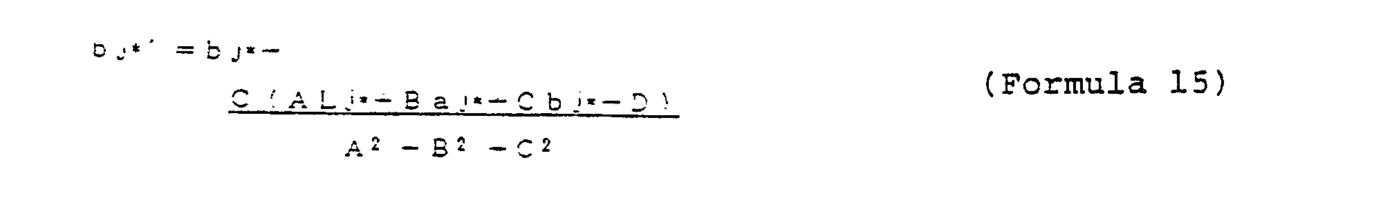
- the coordinates (Lj*', aj*' , bj*') of the bases of perpendiculars passing the sample points (Lj*, aj * , bj * ) CRT and terminating on D j are represented by the Formula 15, based on the Formula 13.
- the final points of movement (Lj * , aj * , bj * )" therefore, :qual the aforementioned (Lj * , aj * , bj*)" with respect to the sample points existing within the range of color reproduction of the copy image.
- the final points of movement (Lj * , aj * , bj * )'" with respect to the sample points of the colors existing outside the range of color reproduction in the copy image equal (Lj*, aj*' bj*).
- the function, ⁇ -'.f which minimizes the color difference between the original image and the copy image is found by subjecting these final points of movement (Lj * , aj * , bj*)"' to the approximation by the least squares method.
- the range of color reproduction in the copy image is conformed with the range of color reproduction in the original image. Since the conformation has also been attained with respect to the white points and the achromatic axes, the copy image faithfully reproducing the color image of the original image as aimed at by the coefficient series 16a can be obtained.
- the control device executes the processing of conversion comprising the steps of sequentially reading original image data from the frame memory 10 via the RGB bus 11 and, with the aid of the data of the lookup "able addressed to the original image data formed in advance at S4, faithfully reproducing the color image of the original image on the copy image (S5;. fn, consequence of the processing of conversion performed at S5, the oriainal image data introduced in the form of RGB signals are converted into the copy image data in the form of YMC signals.
- control device executes a command for causing one line full of image data out of the copy image data obtained by the conversion at S5 to be sequentially stored at a prescribed address in the line buffer memory 14 via the YMC bus 13.
- the control device executes a command to read image data sequentially from the line buffer memory 14 and then a command to transfer the image data to the print mechanism 15 via the YMC bus 13.
- th control device executes a command to drive the print mechanism 15 based on the injected image data. Consequently, the print mechanism 15 prints out the one line full of image data to form print dots (S6).
- the control device judges whether the image data of the last line have been printed out or not (S7). When the judgment draws an affirmative answer, the processing is returned to S2 and left standing there until the print switch is turned on again. If the judgment draws a negative answer, the processing is returned to S5 and allowed to repeat the subsequent steps.
- the present embodiment has been described as using as an output system the setup for storing coefficient series within the ink jet printer.
- the output system is not required to be limited to this particular setup.
- the desired correction of image may be effected instead by causing a coefficient series capable of producing a desired copy image to be transferred to the table forming means from a host computer connected through a suitable interface.
- the processing for conversion of original image data into copy image data possessing a desired color image corrected to suit the state of affairs mentioned above is accomplished.
- a multi- gradation image is to be corrected, for example, or even when some other lookup table is to be prepared to suit the convenience of the input system
- the lookup table is formed improvisatorially each time a new state of affairs arises, the memory region is only required to be enough to store the formed lookup table and is not required to be so large as to permit storage of a plurality of such lookup tables.
- the present invention permits a saving in the memory region.
- Fig. 9 illustrates a second typical construction of the peripheral devices for the image processing apparatus of the present invention.
- This embodiment constructs the peripheral devices of the image processing apparatus by using a host computer provided with external command switches in the place of the CG device and having connected to the multiplex a circuit for discriminating between the operations of external command switch and mode select switch.
- the frame memory 10 disposed inside the ink jet printer 7 is connected via the connecting cable 6 and the interface 23 to the host computer 20.
- This frame memory 10 is adapted to store therein the RGB signal transferred from the host computer 1 and intended to exhibit an original image on the color CRT display 2.
- the host computer 20, the connecting cable 6, and the interface 23 forms function transfer means.
- the term "RGB signal” as used herein refers to a signal for conveying each of the three primary colors, red (R), green (G), and blue (B), in the additive color blend.
- the color CRT display 2 is so adapted as to permit representation of virtually all of the colors by suitably adjusting each of the colors, red (R), green (G), and blue (B), to a suitable intensity by the additive color blend.
- the lookup table memory 12 which forms part of the table forming means is connected to the frame memory 10 through the RGB bus serving to transfer the RGB signals so as to enable the RGB signals adapted for the color CRT display 2 to be converted into the YMC signals adapted for the ink jet printer 7 through reference to the lookup table stored in the frame memory 10.
- the line buffer memory 14 for storing therein one line full of color image data represented by YMC signals is connected to the lookup table memory 12 via the YMC bus 13 serving to transfer the YMC signals which have undergone the conversion in the lookup table memroy 12.
- the print mechanism 15 for forming a color image on the recording paper in accordance with the introduced color image data is connected via the YMC bus 13.
- the computer 18 which forms part of the table forming means is connected to the lookup table momery 12.
- the plurality of coefficient series 16 which have corrective functions for the correction of an original image stored in advance therein and form part of the function storing means are connected to the computer 18.
- the multiplexer 17 having connected thereto a coefficient series region 19 which is connected to the host computer 20 via the aforementioned connecting cable 6 and interface 23, used for storing the corrective functions transferred form the host computer, and adapted to form part of the function storing means capable of memorizing a plurality of corrective functions is also connected to the computer 18.
- a discriminating circuit 22 which has connected to itself a mode select switch 8 for selecting one coefficient series from the plurality of coefficient series 16 and an external command switch 21 for selecting one corrective function from the coefficient series region 19 storing therein a plurality of corrective functions.
- the outcome of selection between the mode select switch 8 and the external command switch 21 is transferred to the multiplexer 17.
- the multiplexer 17, the mode select switch 8, the external command switch 21, and the discriminating circuit 22 jointly form command means.
- a lookup table for the conversion of the original image data into the copy image data in accordance with the coefficient series selected in accordance with the outcome of selection transferred from the discriminating circuit 22 is formed im- iprovisatorially.
- the lookup table thus formed in the computer 18 is transferred to and stored in the lookup table memory 12.
- the lookup talbe is formed in accordance with the selected corrective function.
- the lookup tabl is formed in accordance with a suitable coefficient series which is selected from the coefficient series 16 based on the outcome of the selection made by the mode select switch 8.
- the lookup table is formed in accordance with either coefficient series suitably selected by the mode select switch 8 or the corrective function selected from the coefficient series region by the external command switch 21.
- the image processing apparatus of this embodiment operates to form the copy image in entirely the same manner as described in the first embodiment.
- the present embodiment brings about an effect of permitting instantaneous formation of a lookup table as occasion demands by transferring from the image transfer means to the image storing means a corrective function fit for varying state of affairs of the copy image data involved. Owing to this effect, the apparatus of this embodiment enables the formation of a copy image of desired color image to be realized promptly by a simple operation and enjoys outstanding practical utility.
- the present embodiment has been described as having a mode select switch and an external command switch connected to a discriminating circuit.
- This invention is not required to be limited to this particular arrangement.
- the external command switch may be adapted to combine the function of a mode select switch with the function inherent therein and then connected to the discriminating circuit instead.
- the first and second embodiments have been described with reference to several arrangements for allowing corrective functions to be transferred to and stored in the coefficient series region for the purpose of obtaining a copy image faithfully reproducing the color image of the original image.
- special corrective functions severally adapted for varying conveniences on the part of the input system such as. for example. a first corrective function exclusively used for the first CRT display, a second corrective function for the second CRT display, a third corrective function for the CG image, and a fourth corrective function for the human image may be transferred and stored instead.
- special corrective functions calculated to copy with varying states of affairs of the output system depending on the kind of the inks used in the ink jet printer or the kind of the recording medium may be transferred and stored.
Landscapes
- Engineering & Computer Science (AREA)
- Multimedia (AREA)
- Signal Processing (AREA)
- Facsimile Image Signal Circuits (AREA)
- Color Image Communication Systems (AREA)
Abstract
Description
- This invention relates to a method for processing a color image and an apparatus therefor, particularly to a method of color image processing for converting color original image data into desired color copy image data and an apparatus therefor.
- More particularly, this invention relates to a color image processing method for faithfully reproducing the color image of an input color original image in the form of a color copy image and to a color image processing apparatus for executing the color image processing method by the use of a small memory region.
- Recently, color image processing apparatuses for performing the operation of producing color copy images on recording media based on input color original image data have begun to disseminate in various fields. In the field in which the color image processing apparatuses are utilized as ink jet printers, for example. because of the high excellence in color reproducibility, they find unity mainly in applications specializing in designs of apparels and room interiors, namely the applications which demand faithful color reproduction of original images.
- When a color image given as an original image on a color CRT display and a color image printed out as a copy image by an ink jet printer are compared, they are generally found to lack conformity between the range of reproduction as to color saturation and luminosity of the original image, namely the range of color reproduction, and the range of reproduction of the copy image. For faithful reproduction of the color image of the original image on the reproduced image, therefore, the color image signal being fed into the ink jet printer during the course of the reproduction should be given a correction. The technique disclosed in U.S. Patent No. 4,758,885, for example, effects faithful reproduction of the color image of an original image on a copy image where the range of color reproduction of the color image signal in the input system is wider than that of color reproduction in the output system by causing the input color image to be copied with the range of color reproduction in the input system compressed to that in the output system. This technique, compared with the conventional technique which gives no correction of any sort to the input color image signal, permits reproduction of a copy image rich in gradation.
- The image processing apparatus which executes the conventional method of color image signal processing mentioned above is required to carry out the processing of high intricacy at a high speed. As means of expediting this processing, Japanese Patent Application Disclosure SHO 59(1984)-123.390, for example, teaches a technique which comprises preparing a lookup table storing data necessary for the processing, retreaving pertinent data from the lookup table, and enabling the processing to be speedily carried out based on the output data. When this technique relies solely on the provision of this lookup table. the lookup table is inevitably required to possess a very large capacity such as to jeopardize the economy of the technique itself. To reduce the volume of data stored in one lookup table. therefore, the technique is compelled to make use of a plurality of such lookup tables. In the performance of hard copying based on an input color image signal, a particular lookup table suitable for the quality of the input color image signal is automatically selected from the plurality of lookup tables and an image of ample legibility is formed based on the contents of the selected lookup table. By this technique, the expetition of the processing and the repression of rise of cost are both satisfied.
- While the conventional image processing apparatuses described above are capable of producing copy images rich in gradation, the copy images they produce have the possibility of betraying deficiency in naturality.
- This disadvantage is ascribed to the fact that the conventional method of color image signal processing takes due account exclusively of the conformation of the range of color reproduction between the original image and the copy image and pays no consideration to the white point or the achromatic axis.
- In accordance with the conventional method of color image signal processing, since it pays absolutely no consideration to the conformation of the white point or the achromatic axis, there are times when the gradation is represented while entailing deviation of white level or color hue. When a white color is to be represented, therefore, the white color produced at all appears with a grayish tint. Or when a gray color is to be represented, the produced white color appears with a reddish tint or a blush tint. As the result, the copy image entails the phenomenon of showing a fringe pattern thereon and is possibly deprived conspicuously of naturality.
- An effort to represent an original image in multi-gradation results in a colossal addition to the volume of data to be stored in the lookup table for the correction of multi-gradation images and calls for provision of a large memory region. An effort to store in a memory a multiplicity of lookup tables fit for the status of the input system, for example, necessitates provision of a large memory region.
- This invention aims to provide a method of color image processing free from the various drawbacks suffered by the prior art as described above and an apparatus for working the method. One object of this invention is to provide a method of color image processing for producing a copy image faithfully reproducing the color image of a given original image.
- Another object of this invention is to provide a color image processing apparatus which permits the user to store therein the corrective functions to be used for the formation of lookup tables, call out thereof a corrective function pertinent to the occasion, and consult the lookup table formed based on the retrieved corrective function, requires the memory region thereof to permit storage of the formed loodup tables and not to be so large as to store a plurality of lookup tables independently of one another even when a correction is to be given to a multigradation image or when some other lookup table is to be prepared to suit the prevailing status of the input system, for example, and which consequently allows a saving in the memory region.
-
- Fig. 1 A is a diagram illustrating typically the range of color reproduction of an original image with the CRT display and the range of color reproduction with an ink jet printer, as plotted in the a*-b* coordinates system
- Fig. 1B is a diagram illustrating typically the range of color reproduction sf an original image with the CRT display and the range of color reproduction with an ink jet printer, as plotted in the a"-L" coordinates system.
- Fig. 2 is a diagram illustrating a typical construction of peripheral devices for an image processing apparatus contemplated by the present invention.
- Fig. 3 is a diagram illustrating a circuit for the processing of a color image signal between the peripheral devices for a color image processing apparatus as the first embodiment of this invention.
- Fig. 4 is a flow chart illustrating the operation of the color image signal processing circuit of Fig. 3.
- Fig. 5A and Fig. 5B are explanatory diagrams illustrating the process for effecting conformation of the white point between the CRT reproduction and the hard copy reproduction region.
- Fig. 6A and Fig. 6B are explanatory diagrams illustrating the process for effecting conformation of the chromatic axis between the CRT reproduction and the hard copy reproduction region.
- Fig. 7 is an explanatory diagram illustrating calculation of the points of movement to be produced on conformation of the white point and chromatic axis between the CRT reproduction and the hard copy reproduction region.
- Fig. 8 is an explanatory diagram illustrating the process for causing transfer of the color existing inside the range of color reproduction in an original image and outside the range of color reproduction in a copy image to the surface in the range of color reproduction of the copy image.
- Fig. 9 is a diagram illustrating a color image signal processing circuit disposed between the peripheral devices of the color image processing apparatus as the second embodiment of this invention.
- Now, the present invention will be described in detail below. As a preliminary to the description and for the purpose of facilitating the comprehension of the invention, the essence of the invention will be explained.
- Fig. 1 A and Fig. 1B typically illustrate the range of color reproduction of an original image with the CRT display and the range of color reproduction with the ink jet printer, as plotted respectively in the a*-b" coordinates system and the a*-L' coordinates system.
- As clearly noted from these diagrams, the range of color reproduction of an original image which can be reproduced by the CRT display is wider than the range of color reproduction of a copy image which can be reproduced by the ink jet printer. For the purpose of faithfully reproducing the color image of an original image on a copy image, the range of color reproduction of the original image must be made to conform with the range of color reproduction of the copy image. The present invention, therefore, contempaltes effecting this conformation by fulfilling conformation of the white point and the chromatic axis between the originally image and the copy image. Further, the contents to be stored in the lookup table which is required in attaining this conformation are adapted to be formed at a desired time based on the corrective function to be selected, the memory capacity for the lookup table can be reduced to the fullet possible extent. Thus, the present invention aims to permit a saving in the memory region.
- Now, a working example of the present invention will be described in detail below with reference to Fig. 2 and the following diagrams. As one example of the image processing apparatus, an ink jet printer which is adapted to print out a copy image based on input image data will be illustrated. It is assumed that this ink jet printer is adapted so that an original image exhibited on the color CRT display, one of the component members of a computer graphic apparatus (hereinafter referred to as "CG device" for smort), is transferred thereto.
- Fig. 2 illustrates the construction of peripheral devices for an image processing apparatus an one embodiment of the present invention.
- As illustrated in this diagram, an
ink jet printer 7 is connected through the medium of a connecting cable adapted for transfer of image signals and control signals to aCG device 1 which is composed of acolor CRT display 2, akeyboard 3, a table 4, acontroller 5, etc. Thisink jet printer 7 is provided with a modeselect switch 8 which forms part of command means to be described later on and aprint switch 9 not shown) which is disposed on anoperation panel 9 and used in selecting a print start. - The present embodiment will be described below by citing as an original image a color image to be exhibited on the color CRT display, a component member of the CG device. This invention is not required to be limited to this particular color image. Optionally, it is permissible to use as an original image the image to be represented by a RGB signal such as, for example, a color image which is exhibited on the color CRT display, component member of a CAD device.
- Then, the present embodiment will be described below by citing as a copy image a color image to be printed out from the ink jet printer. This invention is not required to be limited to this particular copy image. It is of course permissible to use as a copy image the image represented by a YMC signal such as, for example, a color image to be printed out by a thermographic or electrostatic printer.
- Fig. 3 illustrates a color image signal processing circuit disposed inside the ink jet printer.
- As illustrated in the diagram, a
frame memory 10 disposed inside the ink jet printer is connected through the medium of a connectingcable 6 and a proper interface (not shown) to theCG device 1. Thisframe memory 10 is adapted to store therein the RGB signal transmitted from theCG device 1 and intended to exhibit an original image on thecolor CRT display 2. - The term "RGB signal" as used herein refers to the signal serving to convey each of the three primary colors, red (R), green (G), and blue (B), in the additive color blend. The
color CRT display 2 is so adapted as to represent virtually all of the colors by effecting the additive color blend through suitable adjustment of the intensity of each of the red (R), green (G), and blue (B) colors. - A
lookup table memory 12 which forms part of table forming means is connected through aRGB bus 11 for the transfer of RGB signals to theframe memory 10. Thislookup table memory 12 is adapted so that the lookup table stored therein lends itself to the conversion of the RGB signal adapted for thecolor CRT display 2 into the YMC signal adapted for theink jet printer 7. The term "YMC signal" as used herein refers to the signal serving to convey each of the three primary colors, yellow (Y), magenta (M), and cyan (C), in the reductive color blend. Theink jet printer 7 is so adapted as to represent virtually all of the colors by effecting the reductive color blend through suitable adjustment of the intensity of each of the yellow (Y), magenta (M), and cyan (C) colors. - A
line buffer memory 14 for storing one line full of color image data represented by the YMC signals is connected to thelookup table memory 12 through the medium of aYMC bus 13 for the transfer of YMC signals which have undergone convertion in thememory 12. Aprint mechanism 15 serving to form a color image on a recording paper based on color image data fed in through theYMC bus 13 is connected to theline buffer memory 14. - The
lookup table memory 12 is connected to acomputer 18 having connected thereto amultiplexer 17 which has a modeselect switch 8 and a plurality ofcoefficient series 16 as means for memorizing corrective functions connected thereto and constitutes itself part of command mans serving to select one coefficient series from the plurality ofcoefficient series 16 in accordance with the setting of the modeselect switch 8. In thiscomputer 18 is formed a lookup table for the conversion of original image data into copy image data based on the coefficient series selected as described above. The lookup table thus formed in thecomputer 18 is transferred to thelookup table memory 12 and stored therein. Thecomputer 18 forms part of the table forming means. In the present embodiment, thecomputer 18 is depicted as connected to themultiplexer 17 having the plurality of coefficient series connected thereto. One coefficient series may suffice. Then, themultiplexer 17 may be omitted. - Now, the operation of the ink jet printer as one embodiment of the present invention will be described with reference to the flow chart of Fig. 4 depicting the operation.
- When a power source switch (not shown) for the
ink jet printer 7 is turned on, the control means inside theink jet printer 7 is initialized (Si ) and readied to start. It is assumed that an original image transferred from theCG device 1 is exhibited on thecolor CRT display 2 and this original image is in a state ready to be transferred, as occasion demands, to theink jet printer 7. It is also assumed that the modeselect switch 8 is set at a proper position. - When the initialization at S1 is completed, the control device judges whether or not the print switch is set on or not (S2). This judgment at S2 is repeated until the print switch is turned on. The control device executes a command for the original image data to be issued from the CG device and admitted in the form of a RGB signal into the
frame memory 10 via the connecting cable 6 (S3) and stored sequentially at a prescribed address in theframe memory 10. The admission of the original image data in theframe memory 10 may be effected before the print switch is turned on. - In the meantime, the control device execute a command for a
particular coefficient series 16 selected by the setting of the modeselect switch 8 to be transferred via themultiplexer 17 to thecomputer 18. Further, the control device reads a pertinent corrective function out of thecorrective function 16 and the original image data out of theframe memory 10 and then executes a command for thecomputer 18 to form a lookup table addressed to the original image data, based on the corrective function (S4). The lookup table formed in thecomputer 18 is stored at a prescribed address on thelookup table memory 12. Since a lookup table is formed improvisatorially each time the print switch is turned on, a saving is attained in the memory region which is required where a plurality of lookup tables are to be stored so as to cope with various states. - When the lookup table is admitted in and allocated to the prescribed address in the
lookup table memory 12, the apparatus is ready for the conversion of the original image into a copy image. - Now, the method for performing the arithmetic operation on a coefficient series 16a, one of the
coefficient series 16 prepared in advance for the purpose of faithfully carrying out the color reproduction of an original image in a copy image, will be described. - First, the color of the original image exhibited on the
color CRT display 2 is represented as (XYZ) CRT by a (XYZ) color system and transferred from theCG device 1 to the color CRT display. When the color represented by the RGB signal is represented as (RGB) CRT by the (RGB) color system, the relation between the two colors is defined by theFormula 1 as widely known. The symbol "f" used in theFormula 1 denotes a proper function representing the characteristic of thecolor CRT display 2. - When the color of the copy image printed out by the
ink jet printer 7 is represented as (XYZ) COPY by the (XYZ) color system and transferred from theframe memory 10 to thelookup table memory 12 and the color represented by the RGB signal is represented as (RGB) COPY by the (RGB) color system, the relation of the two colors is defined by theFormula 2 as well know. The symbol <p used in theFormula 2 denotes a proper function representing the characteristic of theink jet printer 7. - For the color reproduction of the original image in the copy image to be faithfully effected as described above, it suffices to equalize the (XYZ) CRT representing the color of the original image with the (XYZ) COPY representing the color of the copy image. Thus, the establishment of the
Formula 3 is postulated and theFormula 4 is inferred. The coefficient series 16a, therefore, is obtained when the function -'.f in theFormula 4 is fixed.


- Incidentally, the function φ -1.f cannot be exclusively determined. So, this function φ is, therefore, determined by a procedure which comprises extracting a suitable number, N, of representative colors from the ranges of color reproduction respectively of original image and copy image by the use of the (L*a*b*) color system as a uniform perceptive color space, performing on these representative colors an airthmetic operation such as for the conformation of the white color and the conformation of the achromatic axis, and subjecting the representative colors as arithmetically processed to approximation by the least squares method thereby minimizing the color difference between the original image and the copy image.
- Now, the procedure described above will be explored in detail.
- First, the terms L", a*, and b* are calculated by the
Formula 5, i.e. equations for the conversion of the knwon (XYZ) color system to the (L*a*b*) color system. - L' = 116(YY·)

- a* = 500[(X/X·)1/3-(YY.)

- b*=200[(YY.) 1/3-(Z/Z.)

- The symbols X, Y, and Z used in the equations represent three values of stimulus of the standard light source or standard color to be used for the illumination.
- Then, a suitable number, N, of the following representative colors corresponding to the ranges of color reproduction of the original image and the copy image are extracted by the use of the (L*a*b*) color system. (Li*. ai". bi*) CRT
(Li*. ai*, bi*) COPY (Formula)
(wherein i = 1,2,.....j, ....,N ). the following description assumes that the (Lj*, aj* bj*) CRT and the (Lj*, aj*, bj') COPY at the point of sample, i = j, in the N points of sample, fall on a theoretical hypothetic L*-a* plane as illustrated in Fig. 5A. - These sample points (Lj*, aj*, bj*) CRT and (Jj*, aj*. bj*) COPY are moved as shown in Fig. 5B and represented by the
Formula 6 andFormula 7, after the processing for the conformation of the white points existing in the ranges of color reproduction of the original image and the copy image (Lj*. aj*, bj*)' CRT = {(100, 0, 0) - (L W*, aW*, bW*) CRT} + (Lj*, aj*, bj*) CRT (Formula 6) - In this formula, (Jj*, aj*, bj*) CRT represents the point assumed by the point (Lj*, aj*, bj*) CRT after the movement, (100,0,0) the hypothetic white point in the theoretical hypothetic L*-a* plane, and (Lw*, aw*, bw*) CRT the white point in the range of color reproduction of the original image.
(Lj*, aj*, bj*)' COPY= { (100,0,0) - (L
W*. aW*, bW") COPY} + (Lj*, aj*, bj*) COPY (Formula 7) - In this formula, (Lw*, aw*, bw*) COPY represents the white point in the range of color reproduction of the copy image.
- The sample points mentioned above are moved to permit conformation of the white points of the original image and the copy image by subtracting the white points present in the ranges of reproduction of the original image and the copy image from the theoretical hypothetic white points and then adding the sample points, (Lj*, aj*, bj*) CRT or (Lj*, aj*, bj*) COPY, to the resultant differences. This movement is executed on all of the N sample points in the (Lj*, aj*, bj*) CRT and the (Lj*, aj*, bj*) COPY.
- When the processing for the conformation of white points by the arithmetic operation mentioned above is completed, the processing is started for the conformation of the achromatic axis and the theoretical hypothetic achromatic axis L* in the ranges of color reproduction of the original image and the copy image. In this case, the amounts of movement, (Ij, mj, nj) CRT or (ij, mj, nj) COPY, which are required for the conformation of the achromatic axes with the hypothetic achromatic axes L* at the sample points (Lj*, aj*, bj*)' CRT and (Lj*, aj*, bj*) COPY which were moved during the conformation of the white points, among other sample points subjected to the movement are calculated by the use of a function reversely proportional to the distances d from the sample points mentioned above to the achromatic axes so as to increases the amounts of movement of the sample points in the proximity of the achromatic axes. (Ij , mj , nj)' CRT = '(1-dCRT:d' CRT ) (Ij , mj , nj ) CRT (Formula 8)
- In this formula, d CRT represents the shortest distance from the sample point to the achromatic axis, (ij, mj, nj) CRT the distance from the achromatic axis to the hypothetic achromatic axis L*, and d CRT the constant fixed in advance. This constant, d CRT, has an amply larger value than the aforementioned distance, d CRT.
( Ij , mj , nj) ' COPY= (1-dCOPY/d' COPY) ( Ij , mj , nj ) COPY (Formula 9) - In this formula, d COPY, (Ij, mj, nj) COPY, and d COPY have the same meanings as defined above.
- Then, the points of movement (Lj*, aj*, bj*) to be assumed after the conformation of the white points and the achromatic axes are calculated based on the aforementioned calculated points (Lj*, aj*, bj*) and amounts of movement (Ij, mj, nj) , as shown by Fig. 7 and represented by the
Formula 10 andFormula 11.
( Lj*, aj*, bj*) CRT = (Lj*, aj*, bj*) ' CRT + ( Ij , mj , nj) ' CRT (Formula 10)
( Lj*, aj*, bj*) "COPY= (Lj*, aj*, bj*) ' COPY+ (Ij , mj , nj)' COPY (Formula 11) - In the present embodiment, d is treated as substantially equaling the distance from the achromatic axis to the base of a perpendicular of a given sample point subjected to movement drawn across the achromatic axis to the hypothetic achromatic axis. In actuality, this variable d represents the distance between the sample point mentioned above and the achromatic axis in a circle to be described with the white point as the center and the distance from the white point to the sample point as the radius. In the present embodiment, the aforementioned approximate value is taken for d because the simplification of the arithmetic operation is important and the variable d is not required to be very exact. This rule also applies to (Ij, mj, nj).
- Finally, after the white points and the acromatic axes have been conformed as described above,the processing is executed for moving to the surface of the range of color reproduction of the copy image those of the colors existing within the range of color reproduction of the original image which fall outside the range of color reproduction of the copy image as illustrated in Fig. 8.
- By approximating the range of color reproduction in the copy image with a polyhedron of 300 plane faces, for example, representing one of the plane faces as Dj (Lj*, aj*, bj*), and representing the color points existing outside the range of color reproduction of the copy image and inside the range of color reproduction of the original image as (Lj*, aj*, bj*) CRT, the Dj is defined by the
Formula 12 using the constants A, B, C, and D.
A L j*+B a j* + C b j* + D = 0 (Formula 12) - The coordinates (Lj*', aj*' , bj*') of the bases of perpendiculars passing the sample points (Lj*, aj*, bj*) CRT and terminating on Dj are represented by the
Formula 15, based on theFormula 13.

- The final points of movement (Lj*, aj*, bj*)", therefore, :qual the aforementioned (Lj*, aj*, bj*)" with respect to the sample points existing within the range of color reproduction of the copy image. In the case of the colors existing within the range of color reproduction in the original image, the final points of movement (Lj*, aj*, bj*)'" with respect to the sample points of the colors existing outside the range of color reproduction in the copy image equal (Lj*, aj*' bj*).
- Now that the final points of movement (Lj*, aj*, bj*)"' have been calculated, the function, Ø-'.f, which minimizes the color difference between the original image and the copy image is found by subjecting these final points of movement (Lj*, aj*, bj*)"' to the approximation by the least squares method. By forming a lookup table based on he function,Ø-1.f, obtained as described above, namely the coefficient series 16a, and effecting the correction of the original image with reference to the lookup table, the range of color reproduction in the copy image is conformed with the range of color reproduction in the original image. Since the conformation has also been attained with respect to the white points and the achromatic axes, the copy image faithfully reproducing the color image of the original image as aimed at by the coefficient series 16a can be obtained.
- When the formation of the lookup table at S4 is completed, the control device executes the processing of conversion comprising the steps of sequentially reading original image data from the
frame memory 10 via theRGB bus 11 and, with the aid of the data of the lookup "able addressed to the original image data formed in advance at S4, faithfully reproducing the color image of the original image on the copy image (S5;. fn, consequence of the processing of conversion performed at S5, the oriainal image data introduced in the form of RGB signals are converted into the copy image data in the form of YMC signals. - Further, the control device executes a command for causing one line full of image data out of the copy image data obtained by the conversion at S5 to be sequentially stored at a prescribed address in the
line buffer memory 14 via theYMC bus 13. When the storage of the one line full of image data in theline buffer memory 14 is completed, the control device executes a command to read image data sequentially from theline buffer memory 14 and then a command to transfer the image data to theprint mechanism 15 via theYMC bus 13. Then, th control device executes a command to drive theprint mechanism 15 based on the injected image data. Consequently, theprint mechanism 15 prints out the one line full of image data to form print dots (S6). , - After completion of the processing at S6, the control device judges whether the image data of the last line have been printed out or not (S7). When the judgment draws an affirmative answer, the processing is returned to S2 and left standing there until the print switch is turned on again. If the judgment draws a negative answer, the processing is returned to S5 and allowed to repeat the subsequent steps.
- The present embodiment has been described as using as an output system the setup for storing coefficient series within the ink jet printer. The output system is not required to be limited to this particular setup. Optionally, the desired correction of image may be effected instead by causing a coefficient series capable of producing a desired copy image to be transferred to the table forming means from a host computer connected through a suitable interface.
- In the present embodiment, by allowing a lookup table for correcting input image data to suit the prevalent state of affairs to be improvisatorially formed and enabling the formed lookup table to be used for consultation, the processing for conversion of original image data into copy image data possessing a desired color image corrected to suit the state of affairs mentioned above is accomplished. When a multi- gradation image is to be corrected, for example, or even when some other lookup table is to be prepared to suit the convenience of the input system, since the lookup table is formed improvisatorially each time a new state of affairs arises, the memory region is only required to be enough to store the formed lookup table and is not required to be so large as to permit storage of a plurality of such lookup tables. Thus, the present invention permits a saving in the memory region.
- Fig. 9 illustrates a second typical construction of the peripheral devices for the image processing apparatus of the present invention.
- This embodiment constructs the peripheral devices of the image processing apparatus by using a host computer provided with external command switches in the place of the CG device and having connected to the multiplex a circuit for discriminating between the operations of external command switch and mode select switch.
- As illustrated in the diagram, the
frame memory 10 disposed inside theink jet printer 7 is connected via the connectingcable 6 and theinterface 23 to thehost computer 20. Thisframe memory 10 is adapted to store therein the RGB signal transferred from thehost computer 1 and intended to exhibit an original image on thecolor CRT display 2. Thehost computer 20, the connectingcable 6, and theinterface 23 forms function transfer means. The term "RGB signal" as used herein refers to a signal for conveying each of the three primary colors, red (R), green (G), and blue (B), in the additive color blend. Thecolor CRT display 2 is so adapted as to permit representation of virtually all of the colors by suitably adjusting each of the colors, red (R), green (G), and blue (B), to a suitable intensity by the additive color blend. - The
lookup table memory 12 which forms part of the table forming means is connected to theframe memory 10 through the RGB bus serving to transfer the RGB signals so as to enable the RGB signals adapted for thecolor CRT display 2 to be converted into the YMC signals adapted for theink jet printer 7 through reference to the lookup table stored in theframe memory 10. - The
line buffer memory 14 for storing therein one line full of color image data represented by YMC signals is connected to thelookup table memory 12 via theYMC bus 13 serving to transfer the YMC signals which have undergone the conversion in thelookup table memroy 12. To theline buffer memory 14, theprint mechanism 15 for forming a color image on the recording paper in accordance with the introduced color image data is connected via theYMC bus 13. - The
computer 18 which forms part of the table forming means is connected to thelookup table momery 12. The plurality ofcoefficient series 16 which have corrective functions for the correction of an original image stored in advance therein and form part of the function storing means are connected to thecomputer 18. Further, themultiplexer 17 having connected thereto acoefficient series region 19 which is connected to thehost computer 20 via the aforementioned connectingcable 6 andinterface 23, used for storing the corrective functions transferred form the host computer, and adapted to form part of the function storing means capable of memorizing a plurality of corrective functions is also connected to thecomputer 18. To thismultiplexer 17 is connected a discriminatingcircuit 22 which has connected to itself a modeselect switch 8 for selecting one coefficient series from the plurality ofcoefficient series 16 and anexternal command switch 21 for selecting one corrective function from thecoefficient series region 19 storing therein a plurality of corrective functions. The outcome of selection between the modeselect switch 8 and theexternal command switch 21 is transferred to themultiplexer 17. Themultiplexer 17, the modeselect switch 8, theexternal command switch 21, and the discriminatingcircuit 22 jointly form command means. - In the
computer 18 connected to themultiplexer 17 which has connected to itself thecoefficient series 16, thecoefficient series regioin 19, and the discriminatingcircuit 22, a lookup table for the conversion of the original image data into the copy image data in accordance with the coefficient series selected in accordance with the outcome of selection transferred from the discriminatingcircuit 22 is formed im- iprovisatorially. The lookup table thus formed in thecomputer 18 is transferred to and stored in thelookup table memory 12. - Where the mode
select switch 8 has not selected any of thecoefficient series 16 and theexternal command switch 21 has selected a suitable corrective function from thecoefficient series region 19, the lookup talbe is formed in accordance with the selected corrective function. Where the modeselect switch 8 has selected asuitable coefficient series 16 and theexternal command switch 21 has not selected any of the corrective function from thecoefficient series region 19, or where thecoefficient series region 19 has not memorized any corrective function at all, the lookup tabl is formed in accordance with a suitable coefficient series which is selected from thecoefficient series 16 based on the outcome of the selection made by the modeselect switch 8. In short, the lookup table is formed in accordance with either coefficient series suitably selected by the modeselect switch 8 or the corrective functin selected from the coefficient series region by theexternal command switch 21. - After the lookup table is formed as described above, the image processing apparatus of this embodiment operates to form the copy image in entirely the same manner as described in the first embodiment.
- In addition to the effects derived from the first embodiment, the present embodiment brings about an effect of permitting instantaneous formation of a lookup table as occasion demands by transferring from the image transfer means to the image storing means a corrective function fit for varying state of affairs of the copy image data involved. Owing to this effect, the apparatus of this embodiment enables the formation of a copy image of desired color image to be realized promptly by a simple operation and enjoys outstanding practical utility.
- The present embodiment has been described as having a mode select switch and an external command switch connected to a discriminating circuit. This invention is not required to be limited to this particular arrangement. The external command switch may be adapted to combine the function of a mode select switch with the function inherent therein and then connected to the discriminating circuit instead.
- The first and second embodiments have been described with reference to several arrangements for allowing corrective functions to be transferred to and stored in the coefficient series region for the purpose of obtaining a copy image faithfully reproducing the color image of the original image. Otherwise, special corrective functions severally adapted for varying conveniences on the part of the input system such as. for example. a first corrective function exclusively used for the first CRT display, a second corrective function for the second CRT display, a third corrective function for the CG image, and a fourth corrective function for the human image may be transferred and stored instead. Alternatively, special corrective functions calculated to copy with varying states of affairs of the output system, depending on the kind of the inks used in the ink jet printer or the kind of the recording medium may be transferred and stored.
- Where the faithful reproduction does not dictate very strict adherence, corrective functions intended to stress contast of an original image, emphasize the peripheral part of an original image, or similarly modify an original image may be transferred as occasion demends. This arrangement can be easily realized by the analysis of the color characteristics the original image and the copy image.
Claims (4)
Applications Claiming Priority (6)
| Application Number | Priority Date | Filing Date | Title |
|---|---|---|---|
| JP323820/87 | 1987-12-23 | ||
| JP323819/87 | 1987-12-23 | ||
| JP62323819A JPH01165441A (en) | 1987-12-23 | 1987-12-23 | Image processor |
| JP323818/87 | 1987-12-23 | ||
| JP62323818A JP2893682B2 (en) | 1987-12-23 | 1987-12-23 | Color image processing method |
| JP62323820A JPH01166669A (en) | 1987-12-23 | 1987-12-23 | Picture processor |
Publications (3)
| Publication Number | Publication Date |
|---|---|
| EP0321983A2 true EP0321983A2 (en) | 1989-06-28 |
| EP0321983A3 EP0321983A3 (en) | 1990-02-28 |
| EP0321983B1 EP0321983B1 (en) | 1993-09-15 |
Family
ID=27340010
Family Applications (1)
| Application Number | Title | Priority Date | Filing Date |
|---|---|---|---|
| EP88121523A Revoked EP0321983B1 (en) | 1987-12-23 | 1988-12-22 | Method for processing color image and apparatus therefor |
Country Status (3)
| Country | Link |
|---|---|
| US (1) | US5073818A (en) |
| EP (1) | EP0321983B1 (en) |
| DE (1) | DE3884170T2 (en) |
Cited By (16)
| Publication number | Priority date | Publication date | Assignee | Title |
|---|---|---|---|---|
| EP0448250A1 (en) * | 1990-03-06 | 1991-09-25 | Crosfield Electronics Limited | Image data processing |
| WO1991016785A1 (en) * | 1990-04-23 | 1991-10-31 | Linotype-Hell Ag | Process and device for generating a digital printing-colour table for image-reproduction equipment |
| WO1992006557A1 (en) * | 1990-09-28 | 1992-04-16 | Eastman Kodak Company | Color image processing system for preparing a composite image transformation module for performing a plurality of selected image transformations |
| EP0405470A3 (en) * | 1989-06-26 | 1992-04-29 | Seiko Instruments Inc. | Color picture image reading device |
| EP0425253A3 (en) * | 1989-10-24 | 1992-12-16 | Canon Kabushiki Kaisha | Recording apparatus |
| EP0518669A1 (en) * | 1991-06-14 | 1992-12-16 | Canon Kabushiki Kaisha | Image recording apparatus and colo conversion method |
| US5223922A (en) * | 1989-06-26 | 1993-06-29 | Seiko Instruments Inc. | Color picture image reading device with color correction function |
| EP0592146A3 (en) * | 1992-10-05 | 1994-07-20 | Canon Information Syst Inc | Color reproduction method and apparatus |
| EP0606781A1 (en) * | 1993-01-07 | 1994-07-20 | Canon Kabushiki Kaisha | Color image processing apparatus and method, and color image output apparatus |
| US5438649A (en) * | 1992-10-05 | 1995-08-01 | Canon Information Systems, Inc. | Color printing method and apparatus which compensates for Abney effect |
| EP0684728A1 (en) * | 1994-05-26 | 1995-11-29 | Agfa-Gevaert N.V. | Colour matching by systems calibration, linear and non-linear gamut mapping |
| EP0665680A3 (en) * | 1994-01-31 | 1996-01-17 | Canon Kk | Image processing apparatus and method. |
| US5500921A (en) * | 1992-10-05 | 1996-03-19 | Canon Information Systems, Inc. | Method and apparatus for printing high fidelity color reproductions of colors displayed on a monitor |
| US5594558A (en) * | 1990-11-15 | 1997-01-14 | Canon Kabushiki Kaisha | Color image processing apparatus |
| EP0473432B1 (en) * | 1990-08-29 | 1997-06-25 | Xerox Corporation | Color printing |
| EP1202560A3 (en) * | 2000-10-23 | 2005-04-27 | Seiko Epson Corporation | Color correction table generating method, image processing device, image processing method and recording media |
Families Citing this family (31)
| Publication number | Priority date | Publication date | Assignee | Title |
|---|---|---|---|---|
| EP0395452B1 (en) * | 1989-04-28 | 1997-07-02 | Canon Kabushiki Kaisha | Image processing apparatus |
| CA2035666A1 (en) * | 1990-02-05 | 1991-08-06 | Ehud Spiegel | Apparatus and techniques for processing of data such as color images |
| US7221475B1 (en) * | 1990-10-13 | 2007-05-22 | Canon Kabushiki Kaisha | Color image processing apparatus |
| DE69126403T2 (en) * | 1990-11-21 | 1997-10-30 | Canon Kk | Color image transmission device |
| EP0488176B1 (en) * | 1990-11-27 | 1999-03-03 | Canon Kabushiki Kaisha | Color image processing apparatus |
| US5276779A (en) * | 1991-04-01 | 1994-01-04 | Eastman Kodak Company | Method for the reproduction of color images based on viewer adaption |
| JP2630687B2 (en) * | 1991-05-14 | 1997-07-16 | 大日本スクリーン製造株式会社 | Image processing device |
| JP3143508B2 (en) * | 1992-01-08 | 2001-03-07 | キヤノン株式会社 | Image processing method and apparatus |
| US5283670A (en) * | 1992-03-19 | 1994-02-01 | Sony Electronics Inc. | Hardware implementation of an HDTV color corrector |
| US5909291A (en) * | 1992-03-19 | 1999-06-01 | Apple Computer, Inc. | Color matching apparatus and method |
| US5963201A (en) * | 1992-05-11 | 1999-10-05 | Apple Computer, Inc. | Color processing system |
| JPH0668219A (en) * | 1992-08-17 | 1994-03-11 | Fuji Xerox Co Ltd | Color value processor |
| US5754184A (en) * | 1993-01-06 | 1998-05-19 | Eastman Kodak Company | Digital color system and method which provides a visual match across different input and output viewing conditions |
| EP0611231B1 (en) * | 1993-02-12 | 1999-09-29 | Eastman Kodak Company | Method for cross-device color calibration and enhancement using explicit constraints |
| DE69413575T2 (en) * | 1993-02-12 | 1999-05-20 | Eastman Kodak Co., Rochester, N.Y. | Method and device for transforming input color sizes into an input color space into output color sizes into an output color space |
| US5677967A (en) * | 1993-03-10 | 1997-10-14 | R. R. Donnelley & Sons Company | Method of and apparatus for converting between a color appearance space and a colorant space |
| US5956044A (en) * | 1993-05-07 | 1999-09-21 | Eastman Kodak Company | Imaging device to media compatibility and color appearance matching with flare, luminance, and white point comparison |
| US5761480A (en) * | 1994-04-20 | 1998-06-02 | Canon Kabushiki Kaisha | Display control method |
| US5521723A (en) * | 1994-06-16 | 1996-05-28 | Eastman Kodak Company | System for producing a color hardcopy having the color and the tone reproduction characteristics of a photograph |
| JP3771633B2 (en) * | 1996-07-17 | 2006-04-26 | 富士写真フイルム株式会社 | Color correction device |
| KR100200603B1 (en) * | 1996-07-25 | 1999-06-15 | 윤종용 | Color correction device |
| JP4194133B2 (en) | 1998-06-24 | 2008-12-10 | キヤノン株式会社 | Image processing method and apparatus, and storage medium |
| US7126718B1 (en) * | 1999-11-19 | 2006-10-24 | Canon Kabushiki Kaisha | Adjustment of color appearance models |
| WO2002061194A1 (en) * | 2001-01-30 | 2002-08-08 | Milliken & Company | Color change method and product |
| US6588879B2 (en) | 2001-12-03 | 2003-07-08 | Supersample Corporation | Method for ink jet printing a digital image on a textile, the system and apparatus for practicing the method, and products produced by the system and apparatus using the method |
| US7072733B2 (en) * | 2002-01-22 | 2006-07-04 | Milliken & Company | Interactive system and method for design, customization and manufacture of decorative textile substrates |
| JP4721415B2 (en) * | 2005-08-17 | 2011-07-13 | キヤノン株式会社 | Imaging apparatus, information processing apparatus, information processing system, image processing method, control program, and computer-readable storage medium |
| US8334910B2 (en) * | 2007-02-09 | 2012-12-18 | Canon Kabushiki Kaisha | Image capturing apparatus, information processing apparatus, and control methods thereof |
| JP5678584B2 (en) * | 2009-12-16 | 2015-03-04 | 株式会社リコー | Image processing apparatus, image processing method, and program |
| JP5761491B2 (en) | 2010-12-24 | 2015-08-12 | 富士ゼロックス株式会社 | Color processing apparatus and color processing program |
| CN114035197A (en) * | 2021-03-30 | 2022-02-11 | 宁波飞芯电子科技有限公司 | Detection method for obtaining distance information |
Family Cites Families (10)
| Publication number | Priority date | Publication date | Assignee | Title |
|---|---|---|---|---|
| US4477833A (en) * | 1981-08-12 | 1984-10-16 | R. R. Donnelley & Sons Company | Method of color conversion with improved interpolation |
| EP0090596B1 (en) * | 1982-03-30 | 1986-06-25 | Crosfield Electronics Limited | Video retouching systems |
| JPS59123390A (en) * | 1982-12-28 | 1984-07-17 | Seiko Epson Corp | Video printer |
| GB8500493D0 (en) * | 1985-01-09 | 1985-02-13 | Crosfield Electronics Ltd | Video retouching systems |
| US4731662A (en) * | 1985-03-21 | 1988-03-15 | Canon Kabushiki Kaisha | Image processing method for processing an image signal differently depending on the range of an image characteristic thereof relative to the range within which an output device can reproduce the image characteristic |
| US4758885A (en) * | 1985-06-17 | 1988-07-19 | Canon Kabushiki Kaisha | Method of processing color image |
| EP0258740B1 (en) * | 1986-09-02 | 1995-07-19 | Fuji Photo Film Co., Ltd. | Method of and apparatus for processing an image with gradation correction of video signal |
| JPH0724425B2 (en) * | 1986-09-02 | 1995-03-15 | 富士写真フイルム株式会社 | Image processing method and apparatus |
| GB8722228D0 (en) * | 1987-09-22 | 1987-10-28 | Crosfield Electronics Ltd | Image processing |
| GB8723203D0 (en) * | 1987-10-02 | 1987-11-04 | Crosfield Electronics Ltd | Interactive image modification |
-
1988
- 1988-12-21 US US07/287,841 patent/US5073818A/en not_active Expired - Lifetime
- 1988-12-22 DE DE88121523T patent/DE3884170T2/en not_active Revoked
- 1988-12-22 EP EP88121523A patent/EP0321983B1/en not_active Revoked
Cited By (28)
| Publication number | Priority date | Publication date | Assignee | Title |
|---|---|---|---|---|
| EP0405470A3 (en) * | 1989-06-26 | 1992-04-29 | Seiko Instruments Inc. | Color picture image reading device |
| US5223922A (en) * | 1989-06-26 | 1993-06-29 | Seiko Instruments Inc. | Color picture image reading device with color correction function |
| US6535631B1 (en) | 1989-10-24 | 2003-03-18 | Canon Kabushiki Kaisha | Recording apparatus |
| EP0425253A3 (en) * | 1989-10-24 | 1992-12-16 | Canon Kabushiki Kaisha | Recording apparatus |
| US6198840B1 (en) | 1989-10-24 | 2001-03-06 | Canon Kabushiki Kaisha | Recording apparatus |
| US6731791B2 (en) | 1989-10-24 | 2004-05-04 | Canon Kabushiki Kaisha | Recording apparatus |
| US5647020A (en) * | 1989-10-24 | 1997-07-08 | Canon Kabushiki Kaisha | Recording apparatus |
| US5463480A (en) * | 1990-03-06 | 1995-10-31 | Crosfield Electronics Limited | Image processor for output devices which transforms data into acceptable color space |
| EP0448250A1 (en) * | 1990-03-06 | 1991-09-25 | Crosfield Electronics Limited | Image data processing |
| WO1991016785A1 (en) * | 1990-04-23 | 1991-10-31 | Linotype-Hell Ag | Process and device for generating a digital printing-colour table for image-reproduction equipment |
| US5398121A (en) * | 1990-04-23 | 1995-03-14 | Linotype-Hell Ag | Method and device for generating a digital lookup table for printing inks in image reproduction equipment |
| EP0473432B1 (en) * | 1990-08-29 | 1997-06-25 | Xerox Corporation | Color printing |
| WO1992006557A1 (en) * | 1990-09-28 | 1992-04-16 | Eastman Kodak Company | Color image processing system for preparing a composite image transformation module for performing a plurality of selected image transformations |
| EP0486311B1 (en) * | 1990-11-15 | 2001-10-10 | Canon Kabushiki Kaisha | Color image processing apparatus and method |
| US5844699A (en) * | 1990-11-15 | 1998-12-01 | Canon Kabushiki Kaisha | Color image processing apparatus |
| US5594558A (en) * | 1990-11-15 | 1997-01-14 | Canon Kabushiki Kaisha | Color image processing apparatus |
| EP0518669A1 (en) * | 1991-06-14 | 1992-12-16 | Canon Kabushiki Kaisha | Image recording apparatus and colo conversion method |
| US5552905A (en) * | 1991-06-14 | 1996-09-03 | Canon Kabushiki Kaisha | Image processing apparatus which selects a type of color processing for color image data based on a characteristic of the color image data |
| US5500921A (en) * | 1992-10-05 | 1996-03-19 | Canon Information Systems, Inc. | Method and apparatus for printing high fidelity color reproductions of colors displayed on a monitor |
| US5438649A (en) * | 1992-10-05 | 1995-08-01 | Canon Information Systems, Inc. | Color printing method and apparatus which compensates for Abney effect |
| EP0592146A3 (en) * | 1992-10-05 | 1994-07-20 | Canon Information Syst Inc | Color reproduction method and apparatus |
| US5949427A (en) * | 1993-01-07 | 1999-09-07 | Canon Kabushiki Kaisha | Color image processing apparatus and method and color image output apparatus each using a color matching/processing method based on the color imput |
| EP0606781A1 (en) * | 1993-01-07 | 1994-07-20 | Canon Kabushiki Kaisha | Color image processing apparatus and method, and color image output apparatus |
| EP0665680A3 (en) * | 1994-01-31 | 1996-01-17 | Canon Kk | Image processing apparatus and method. |
| US6044173A (en) * | 1994-01-31 | 2000-03-28 | Canon Kabushiki Kaisha | Image processing apparatus and method |
| EP0684728A1 (en) * | 1994-05-26 | 1995-11-29 | Agfa-Gevaert N.V. | Colour matching by systems calibration, linear and non-linear gamut mapping |
| EP1202560A3 (en) * | 2000-10-23 | 2005-04-27 | Seiko Epson Corporation | Color correction table generating method, image processing device, image processing method and recording media |
| US7061646B2 (en) | 2000-10-23 | 2006-06-13 | Seiko Epson Corporation | Color correction table generating method, image processing device, image processing method and recording media |
Also Published As
| Publication number | Publication date |
|---|---|
| EP0321983B1 (en) | 1993-09-15 |
| DE3884170T2 (en) | 1994-04-21 |
| DE3884170D1 (en) | 1993-10-21 |
| EP0321983A3 (en) | 1990-02-28 |
| US5073818A (en) | 1991-12-17 |
Similar Documents
| Publication | Publication Date | Title |
|---|---|---|
| EP0321983B1 (en) | Method for processing color image and apparatus therefor | |
| US4481532A (en) | Method of determining and storing color printing information | |
| US4929978A (en) | Color correction method for color copier utilizing correction table derived from printed color samples | |
| US5162899A (en) | Color data correction apparatus ultilizing neural network | |
| EP0308858B1 (en) | Method of correcting color image data for obtaining proof image | |
| US4598282A (en) | Video retouching system | |
| US5710872A (en) | Color image recording device, system, and method | |
| US4656505A (en) | Method for color correction for multi-color printing plate pictures | |
| US5546195A (en) | Apparatus for reproducing color images | |
| US4668980A (en) | Video retouching systems | |
| US4496968A (en) | Reproduction of colored images | |
| EP0851669A2 (en) | Color transforming method | |
| JPH08116456A (en) | Image processing unit | |
| US4551751A (en) | Color reduction dependent on tone | |
| US4941037A (en) | Color image processing method and apparatus in which a gradation-converted luminance signal and two non-linearly quantized color-difference signals having fewer bits than the luminance signal are used to address a color masking ROM | |
| US5915075A (en) | Image processing apparatus for converting input color chart data into color data for an output device | |
| US5552905A (en) | Image processing apparatus which selects a type of color processing for color image data based on a characteristic of the color image data | |
| JP2893682B2 (en) | Color image processing method | |
| JPH04335771A (en) | Color correcting device | |
| JPH04304775A (en) | Color correction method for color image signals | |
| US4974070A (en) | Colorgraphic reproduction system | |
| JPH04217167A (en) | Color image processing method | |
| JPH01165441A (en) | Image processor | |
| JPH01166669A (en) | Picture processor | |
| JP2744437B2 (en) | Color converter |
Legal Events
| Date | Code | Title | Description |
|---|---|---|---|
| PUAI | Public reference made under article 153(3) epc to a published international application that has entered the european phase |
Free format text: ORIGINAL CODE: 0009012 |
|
| AK | Designated contracting states |
Kind code of ref document: A2 Designated state(s): DE FR GB |
|
| PUAL | Search report despatched |
Free format text: ORIGINAL CODE: 0009013 |
|
| 17P | Request for examination filed |
Effective date: 19891127 |
|
| AK | Designated contracting states |
Kind code of ref document: A3 Designated state(s): DE FR GB |
|
| 17Q | First examination report despatched |
Effective date: 19920312 |
|
| GRAA | (expected) grant |
Free format text: ORIGINAL CODE: 0009210 |
|
| AK | Designated contracting states |
Kind code of ref document: B1 Designated state(s): DE FR GB |
|
| REF | Corresponds to: |
Ref document number: 3884170 Country of ref document: DE Date of ref document: 19931021 |
|
| ET | Fr: translation filed | ||
| PLBI | Opposition filed |
Free format text: ORIGINAL CODE: 0009260 |
|
| 26 | Opposition filed |
Opponent name: HI-TEC ELECTRONIK VERTRIEBS GMBH Effective date: 19940615 |
|
| PGFP | Annual fee paid to national office [announced via postgrant information from national office to epo] |
Ref country code: FR Payment date: 19951116 Year of fee payment: 8 |
|
| PGFP | Annual fee paid to national office [announced via postgrant information from national office to epo] |
Ref country code: GB Payment date: 19951201 Year of fee payment: 8 |
|
| PGFP | Annual fee paid to national office [announced via postgrant information from national office to epo] |
Ref country code: DE Payment date: 19960220 Year of fee payment: 8 |
|
| RDAG | Patent revoked |
Free format text: ORIGINAL CODE: 0009271 |
|
| STAA | Information on the status of an ep patent application or granted ep patent |
Free format text: STATUS: PATENT REVOKED |
|
| 27W | Patent revoked |
Effective date: 19960206 |
|
| GBPR | Gb: patent revoked under art. 102 of the ep convention designating the uk as contracting state |
Free format text: 960206 |