EP0321906A2 - Mechanism for locating a flexible photoconductor relative to a development station - Google Patents
Mechanism for locating a flexible photoconductor relative to a development station Download PDFInfo
- Publication number
- EP0321906A2 EP0321906A2 EP88121230A EP88121230A EP0321906A2 EP 0321906 A2 EP0321906 A2 EP 0321906A2 EP 88121230 A EP88121230 A EP 88121230A EP 88121230 A EP88121230 A EP 88121230A EP 0321906 A2 EP0321906 A2 EP 0321906A2
- Authority
- EP
- European Patent Office
- Prior art keywords
- station
- arms
- bearing member
- image bearing
- roller
- Prior art date
- Legal status (The legal status is an assumption and is not a legal conclusion. Google has not performed a legal analysis and makes no representation as to the accuracy of the status listed.)
- Granted
Links
Images

Classifications
-
- G—PHYSICS
- G03—PHOTOGRAPHY; CINEMATOGRAPHY; ANALOGOUS TECHNIQUES USING WAVES OTHER THAN OPTICAL WAVES; ELECTROGRAPHY; HOLOGRAPHY
- G03G—ELECTROGRAPHY; ELECTROPHOTOGRAPHY; MAGNETOGRAPHY
- G03G15/00—Apparatus for electrographic processes using a charge pattern
- G03G15/75—Details relating to xerographic drum, band or plate, e.g. replacing, testing
- G03G15/754—Details relating to xerographic drum, band or plate, e.g. replacing, testing relating to band, e.g. tensioning
-
- G—PHYSICS
- G03—PHOTOGRAPHY; CINEMATOGRAPHY; ANALOGOUS TECHNIQUES USING WAVES OTHER THAN OPTICAL WAVES; ELECTROGRAPHY; HOLOGRAPHY
- G03G—ELECTROGRAPHY; ELECTROPHOTOGRAPHY; MAGNETOGRAPHY
- G03G15/00—Apparatus for electrographic processes using a charge pattern
- G03G15/06—Apparatus for electrographic processes using a charge pattern for developing
- G03G15/08—Apparatus for electrographic processes using a charge pattern for developing using a solid developer, e.g. powder developer
- G03G15/0896—Arrangements or disposition of the complete developer unit or parts thereof not provided for by groups G03G15/08 - G03G15/0894
-
- G—PHYSICS
- G03—PHOTOGRAPHY; CINEMATOGRAPHY; ANALOGOUS TECHNIQUES USING WAVES OTHER THAN OPTICAL WAVES; ELECTROGRAPHY; HOLOGRAPHY
- G03G—ELECTROGRAPHY; ELECTROPHOTOGRAPHY; MAGNETOGRAPHY
- G03G15/00—Apparatus for electrographic processes using a charge pattern
- G03G15/22—Apparatus for electrographic processes using a charge pattern involving the combination of more than one step according to groups G03G13/02 - G03G13/20
- G03G15/28—Apparatus for electrographic processes using a charge pattern involving the combination of more than one step according to groups G03G13/02 - G03G13/20 in which projection is obtained by line scanning
- G03G15/283—Apparatus for electrographic processes using a charge pattern involving the combination of more than one step according to groups G03G13/02 - G03G13/20 in which projection is obtained by line scanning using a reusable recording medium in form of a band
Abstract
Description
- This invention relates to a mechanism for locating a back-up roller inside an endless photoconductor and opposite a magnetic brush of a development station on the outside of the photoconductor so that the photoconductor is precisely located with respect to the station.
- U.S. Patent No. 3,974,952 entitled "Web Tracking Apparatus" issued on August 17, 1976 in the names of T. Swanke et al. The apparatus disclosed in that patent includes a pair of spaced, fixed plates for supporting a plurality of rollers. An endless flexible photoconductor is carried by the rollers and advanced past a series of stations, including a development station that is outside the endless loop formed by the photoconductor. A series of back-up rollers between the plates are located inside the loop formed by the photoconductor and opposite the development station to help establish the plane of the photoconductor relative to the development station.
- Apparatus as generally described above has been used successfully in prior copiers/duplicators. In one such copier/duplicator, as the development station is moved into place relative to the photoconductor, the toning roller of a magnetic brush apparatus is located with respect to the back-up roller (and thus the photoconductor) by a four-point mounting including a guide. This system has several disadvantages. For example, the four point system is an over restrained system, it does not always provide the required accuracy of alignment relative to the back-up rollers and photoconductors, and it makes removal of the station difficult. In another copier/duplicator the development station moves into position in a tray and adjustments are provided to move the toning roller with respect to the photoconductor and the back-up roller. These prior systems work satisfactorily even though the back-up roller, toning roller and photoconductor may not be precisely located with respect to each other, especially in a front-to-rear direction (i.e., laterally relative to the photoconductor). However, a new development station for an improved developer material requires more accuracy in establishment of the plane of the photoconductor with respect to the toning roller. Thus, improved mechanisms are needed to meet this requirement.
- Accordingly, it is an object of the invention to improve the accuracy of alignment of a flexible image bearing member, such as a photoconductor, relative to a development station, especially in a lateral direction relative to the photoconductor. Another object is to provide accurate positioning of the image bearing member or photoconductor relative to the development station while avoiding an over restrained system and without complicating removal of the development station. The present invention can be used in a reproduction apparatus having a flexible image bearing member such as a photoconductor trained about a plurality of rollers for movement along a path. The photoconductor has first and second surfaces, and a development station is positioned along the path adjacent the first surface for developing latent images on the first surface of the photoconductor. The mechanism of the invention is used for locating the photoconductor relative to the station, and is characterized by means defining two spaced stops on the station, a back-up roller that is mounted adjacent the second surface of the photoconductor for movement toward and away from the development station and that is effective when moved toward the development station to deflect the photoconductor toward the development station, and by means associated with the mounting means and engageable with the stops for limiting movement of the back-up roller, and therefore of the photoconductor, toward the development station, in order to establish the precise location of the photoconductor relative to the station.
- In the detailed description of the preferred embodiment of the invention presented below reference is made to the accompanying drawings, in which:
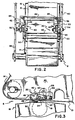
- Fig. 1 is an elevation view of portions of a reproduction apparatus incorporating a preferred embodiment of a mechanism of the inventions for locating a back-up roller and photoconductor relative to the applicator of a development station;
- Fig. 2 is a fragmentary plane view of portions of the Fig. 1 apparatus; and
- Fig. 3 is a detail view of part of the Fig. 1 mechanism showing a second position of some of the parts.
- The mechanism of the invention can be used with a reproduction apparatus, a portion of which is generally designated 8.
Apparatus 8 can be an electrographic copier/duplicator as generally disclosed in the before-mentioned U.S. Patent No. 3.974,952, and the disclosure of such patent is incorporated herein. Theapparatus 8 includes an image bearing member such as aphotoconductor 10 that is supported for movement along an endless path by a plurality of rollers, three of which are shown at 12, 14 and 16.Roller 16, together withroller 12, holds the photoconductor flat in an image plane so that a latent image can be formed on the photoconductor. - The
apparatus 8 has a development station generally shown at 18 including an applicator, such as atoning roller 19 of a magnetic brush.Station 18 is moved into its operative position inapparatus 8 on rails (not shown) and located in a fixed position with respect to therollers Station 18 is outside the endless path of the photoconductor and below the portion of the photoconductor betweenrollers - The mechanism of the invention for urging the image bearing member or photoconductor into position with respect to the development station is generally designated 20.
Mechanism 20 includes abar 22 spaced from the photoconductor and positioned within the loop formed by the image bearing member or photoconductor as shown in Fig. 2, twoarms bar 22. Twoadditional arms arms pivots 32 and 34.Arms Arms torque spring 37 can be coiled around each of thepivots 32, 34 and have its ends connected toarms arms - Fixed
plates 38, 40 at the rear and front, respectively, of the reproduction apparatus support therollers Mechanism 20 also is supported by these plates. More specifically,arms pivots 32 and 34 to rear andfront plates 38, 40, respectively. Pivotal movement of thearms pin 42 on each arm which projects through a slot 44 (Fig. 1) inarms arms corresponding arms pin 45 projects fromplate 40 to a position over the top ofarm 30.Pin 45 limits upward movement ofarm 30, and thus limits movement of all of themechanism 20 aboutpivots 32, 34. - A back-
up roller 46 for the photoconductor is located inside the endless loop of the photoconductor.Roller 46 is carried by thearms roller 46 toward thephotoconductor 10 is limited by projections on the bottom of eacharm arm 30 in Fig. 1. Such projections are engageable withstops 50 that are fixed with respect to the frame androller 19 of thedevelopment station 18. The stops are located directly below theprojections 48, and both the stops and projections are laterally offset from the path ofphotoconductor 10. Thusarms rollers roller 19 ofstation 18. - The
development station 18 has a ramp-shaped cam 52 (Figs. 1 and 2). When the station is moved into position in the reproduction apparatus the upper edge of the cam engages the bottom ofarm 26 to urge the arm upwardly about itspivot 34. This movement is transferred throughbar 22 toarm 24, causing it to move about its pivot 32. Asarms springs 37 urge the back-uproller 46 downwardly into contact with the photoconductor. The force ofsprings 37 urgesarms projections 48 independently engage thestops 50. The back-up roller 46, together withroller 16, then establishes the location of thephotoconductor 10 with respect to thetoning roller 19 instation 18. - Operation of the apparatus of the invention will now be described. With the
development station 18 at least partly removed from the apparatus as shown in Fig. 3,cam 52 is separated fromarm 26. This permits the force of gravity to swing themechanism 20 aboutpivots 32 and 34 to a position shown in Fig. 3 where the upper edge ofarm 30 contacts stoppin 45. This locatesroller 46 in its raised position away fromphotoconductor 10. Under theseconditions arms pivots 32, 34. Withroller 46 elevated,photoconductor 10 will be in a substantially flat plane between the bottom ofrollers - During movement of
station 18 into its loaded position in the reproduction apparatus, it moves freely beneath the plane of the photoconductor becausemechanism 20 is in its Fig. 3 position and the photoconductor is above the path of the station. Asstation 18 reaches its fully loaded position,cam 52 engages the bottom surface ofarm 26 to pivot the arm in a counterclockwise direction aboutpivot 34 to its Fig. 1 position. This movement is translated throughbar 22 to thearm 24 to cause corresponding movement ofarm 24. The torsion springs 37 then exert a force onarms pivots 32 and 34 until both theprojections 48 engage thestops 50 on thestation 18. As this occurs theroller 46 contacts the inner surface of thephotoconductor 10 to move the photoconductor downwardly relative to the toningroller 19. This locates the photoconductor in a plane between the bottom ofroller 16 and the bottom ofroller 46, such plane being just above the toningroller 19. The plane of the photoconductor relative to the toning roller is very precisely located because theprojections 48 are on thearms roller 46, and such projections contact thestops 50 at the front and rear of the development station, such stops being fixed with respect to toningroller 19. - It is important that the
roller 46 be precisely located with respect to the development station at both the front and rear ends of the station. One reason such precise location is achieved withmechanism 20 is that springs 37 urge thearms projection 48 on one of these arms strikes astop 50, the other arm can continue to move independently until it too strikes itsstop 50. Thus both arms will contact their respective stops to exactly locate theroller 46 relative to the stops, and also relative toroller 19. - The advantages of the mechanism of the invention in locating the photoconductor relative to the toning roller include the fact that it is not an over restrained system as is the case in some prior apparatus. In addition, the mechanism quite accurately aligns the back-up
roller 46, and thus the photoconductor, relative to the toningroller 19 with great precision so that there is little or no variability between the spacing of the photoconductor at the edge thereof nearest the front of the reproduction apparatus as compared to the spacing near the rear of the reproduction apparatus. Thus the apparatus of the invention is usable with developer materials which require the photoconductor to be established very precisely with respect to the toning roller. Moreover, the apparatus of the invention does not interfere with the removal or insertion ofstation 18.
Claims (6)
means defining two spaced stops (50) on the station,
a back-up means (46),
means (24, 26) mounting the back-up means adjacent the second surface of the image bearing member for movement toward and away from the development station, the back-up means being effective when moved toward the development station to deflect the image bearing member toward the development station, and
means (48) engageable with the stops (50) for limiting movement of the back-up means and thus of the image bearing member, toward the development station, thereby establishing the location of the image bearing member relative to the station.
means defining two spaced stops (50) on the station, one stop (50) being laterally offset from one side of the path and the other stop (50) being laterally offset from the other side of the path,
a bar (22) adjacent the second surface of the image bearing member,
first and second arms (24, 26) rigidly secured to opposite ends of the bar,
means (32, 34) for pivotally mounting the first and second arms for movement about an axis,
a third arm (28) pivotally connected to the first arm,
a fourth arm (30) pivotally connected to the second arm,
a back-up roller (46) carried by the third and fourth arms and located adjacent the second surface of the image bearing member,
means (37) for independently urging the third and fourth arms about their respective pivotal connection to the first and third arms,
means (48) on the third and fourth arms engageable with the stops (50) in response to movement of such arms for locating the back-up roller precisely relative to the development station,
thereby locating the image bearing member relative to the station.
Applications Claiming Priority (2)
| Application Number | Priority Date | Filing Date | Title |
|---|---|---|---|
| US135860 | 1987-12-21 | ||
| US07/135,860 US4806991A (en) | 1987-12-21 | 1987-12-21 | Mechanism for locating a flexible photoconductor relative to a development station |
Publications (3)
| Publication Number | Publication Date |
|---|---|
| EP0321906A2 true EP0321906A2 (en) | 1989-06-28 |
| EP0321906A3 EP0321906A3 (en) | 1990-11-28 |
| EP0321906B1 EP0321906B1 (en) | 1993-11-18 |
Family
ID=22470051
Family Applications (1)
| Application Number | Title | Priority Date | Filing Date |
|---|---|---|---|
| EP88121230A Expired - Lifetime EP0321906B1 (en) | 1987-12-21 | 1988-12-19 | Mechanism for locating a flexible photoconductor relative to a development station |
Country Status (4)
| Country | Link |
|---|---|
| US (1) | US4806991A (en) |
| EP (1) | EP0321906B1 (en) |
| JP (1) | JPH01206377A (en) |
| DE (1) | DE3885721T2 (en) |
Cited By (1)
| Publication number | Priority date | Publication date | Assignee | Title |
|---|---|---|---|---|
| EP0424137A2 (en) * | 1989-10-18 | 1991-04-24 | Konica Corporation | Color image forming apparatus |
Families Citing this family (9)
| Publication number | Priority date | Publication date | Assignee | Title |
|---|---|---|---|---|
| US5363183A (en) * | 1991-09-06 | 1994-11-08 | Xerox Corporation | Copying machine with device for removing carrier beads from the photoconductive surface |
| US5485190A (en) * | 1993-05-20 | 1996-01-16 | Eastman Kodak Company | Printhead writer assembly engageable with a web image member |
| US5604570A (en) * | 1994-06-30 | 1997-02-18 | Hewlett-Packard Company | Electrophotographic printer with apparatus for moving a flexible photoconductor into engagement with a developer module |
| US5515147A (en) * | 1994-10-28 | 1996-05-07 | Eastman Kodak Company | Mechanism for substantially preventing trail edge smear of an image on a receiver member |
| US5572296A (en) * | 1994-11-23 | 1996-11-05 | Xerox Corporation | Color printing system employing non-interactive development |
| US5953565A (en) * | 1997-04-11 | 1999-09-14 | Xerox Corporation | Developer backer bar that allows axial misalignment between the backer bar and the developer donor roll |
| US6035161A (en) * | 1998-06-26 | 2000-03-07 | Xerox Corporation | Developer backer bar that allows a large amount of photoreceptor wrap with minimal surface contact area for greater axial misalignment |
| US6813128B2 (en) * | 2001-05-25 | 2004-11-02 | Nexpress Solutions Llc | High voltage bias feedback for diagnostic purposes |
| US6751429B1 (en) | 2002-12-16 | 2004-06-15 | Xerox Corporation | Compliant backer bar |
Citations (6)
| Publication number | Priority date | Publication date | Assignee | Title |
|---|---|---|---|---|
| US3974952A (en) * | 1974-09-10 | 1976-08-17 | Eastman Kodak Company | Web tracking apparatus |
| EP0142917A2 (en) * | 1983-10-24 | 1985-05-29 | Matsushita Electric Industrial Co., Ltd. | Electrophotographic copier |
| JPS60164778A (en) * | 1984-02-07 | 1985-08-27 | Matsushita Electric Ind Co Ltd | Electrophotographic copying machine |
| US4630919A (en) * | 1985-07-22 | 1986-12-23 | Xerox Corporation | Selectable color system |
| US4703334A (en) * | 1983-08-26 | 1987-10-27 | Ricoh Company, Ltd. | Optical recording head and belt positioning apparatus |
| EP0321905A2 (en) * | 1987-12-21 | 1989-06-28 | EASTMAN KODAK COMPANY (a New Jersey corporation) | Mechanism for locating a flexible photoconductor relative to a plurality of development stations |
Family Cites Families (7)
| Publication number | Priority date | Publication date | Assignee | Title |
|---|---|---|---|---|
| NL183059C (en) * | 1974-06-27 | 1988-07-01 | Oce Van Der Grinten Nv | FLUID APPLICATION DEVICE. |
| US4114536A (en) * | 1976-08-26 | 1978-09-19 | Ricoh Co., Ltd. | Method of and apparatus for transfer printing a toner image |
| US4361112A (en) * | 1980-03-27 | 1982-11-30 | Coulter Systems Corporation | Apparatus for developing latent electrostatic images |
| US4398496A (en) * | 1982-07-16 | 1983-08-16 | Xerox Corporation | Multi-roll development system |
| US4565437A (en) * | 1983-11-09 | 1986-01-21 | Xerox Corporation | Hybrid development system |
| US4575217A (en) * | 1984-12-04 | 1986-03-11 | Eastman Kodak Company | Apparatus for selectively sealing a discrete dielectric sheet developer station |
| US4699500A (en) * | 1986-11-17 | 1987-10-13 | Eastman Kodak Company | Electrographic copier with three development stations |
-
1987
- 1987-12-21 US US07/135,860 patent/US4806991A/en not_active Expired - Lifetime
-
1988
- 1988-12-19 EP EP88121230A patent/EP0321906B1/en not_active Expired - Lifetime
- 1988-12-19 DE DE3885721T patent/DE3885721T2/en not_active Expired - Lifetime
- 1988-12-21 JP JP63323175A patent/JPH01206377A/en active Pending
Patent Citations (6)
| Publication number | Priority date | Publication date | Assignee | Title |
|---|---|---|---|---|
| US3974952A (en) * | 1974-09-10 | 1976-08-17 | Eastman Kodak Company | Web tracking apparatus |
| US4703334A (en) * | 1983-08-26 | 1987-10-27 | Ricoh Company, Ltd. | Optical recording head and belt positioning apparatus |
| EP0142917A2 (en) * | 1983-10-24 | 1985-05-29 | Matsushita Electric Industrial Co., Ltd. | Electrophotographic copier |
| JPS60164778A (en) * | 1984-02-07 | 1985-08-27 | Matsushita Electric Ind Co Ltd | Electrophotographic copying machine |
| US4630919A (en) * | 1985-07-22 | 1986-12-23 | Xerox Corporation | Selectable color system |
| EP0321905A2 (en) * | 1987-12-21 | 1989-06-28 | EASTMAN KODAK COMPANY (a New Jersey corporation) | Mechanism for locating a flexible photoconductor relative to a plurality of development stations |
Non-Patent Citations (1)
| Title |
|---|
| PATENT ABSTRACTS OF JAPAN, vol. 10, no. 9 (P-420)[2066], 14th January 1986; & JP-A-60 164 778 (MATSUSHITA DENKI SANGYO K.K.) 27-08-1985 * |
Cited By (3)
| Publication number | Priority date | Publication date | Assignee | Title |
|---|---|---|---|---|
| EP0424137A2 (en) * | 1989-10-18 | 1991-04-24 | Konica Corporation | Color image forming apparatus |
| EP0424137A3 (en) * | 1989-10-18 | 1992-07-22 | Konica Corporation | Color image forming apparatus |
| US5168318A (en) * | 1989-10-18 | 1992-12-01 | Konica Corporation | Color image forming apparatus having a predetermined space maintained between a photosensitive belt and developing devices |
Also Published As
| Publication number | Publication date |
|---|---|
| EP0321906A3 (en) | 1990-11-28 |
| US4806991A (en) | 1989-02-21 |
| DE3885721D1 (en) | 1993-12-23 |
| EP0321906B1 (en) | 1993-11-18 |
| DE3885721T2 (en) | 1994-05-19 |
| JPH01206377A (en) | 1989-08-18 |
Similar Documents
| Publication | Publication Date | Title |
|---|---|---|
| KR940009452B1 (en) | Sheet feeding apparatus | |
| EP0075398B1 (en) | A belt alignment apparatus | |
| JPH0323464B2 (en) | ||
| US4806991A (en) | Mechanism for locating a flexible photoconductor relative to a development station | |
| CA2036663C (en) | Electrophotographic apparatus | |
| US3627312A (en) | Restacking apparatus | |
| US4547059A (en) | Image-transfer-type electrostatic recording apparatus | |
| US4809033A (en) | Image forming apparatus and process cartridge therefor | |
| EP0322219A2 (en) | Image forming apparatus | |
| EP0321905B1 (en) | Mechanism for locating a flexible photoconductor relative to a plurality of development stations | |
| EP0307942B1 (en) | Mechanisms in image recording apparatus | |
| JPS6212512B2 (en) | ||
| US4171899A (en) | Transfer apparatus | |
| EP0784239B1 (en) | High capacity cassette tray assembly | |
| JPS63128387A (en) | Belt apparatus | |
| JPH1115355A (en) | Image forming device | |
| JP3247012B2 (en) | Image forming device | |
| JP4256696B2 (en) | Image forming apparatus | |
| US4919409A (en) | Sheet handling apparatus with narrow belt having raised frictional contact element | |
| JP3407256B2 (en) | Paper transport device | |
| JPH0123140Y2 (en) | ||
| US3628786A (en) | Document-handling apparatus | |
| EP0142917A2 (en) | Electrophotographic copier | |
| US3984099A (en) | Document feeding system | |
| JPS63139850A (en) | Recording device |
Legal Events
| Date | Code | Title | Description |
|---|---|---|---|
| PUAI | Public reference made under article 153(3) epc to a published international application that has entered the european phase |
Free format text: ORIGINAL CODE: 0009012 |
|
| AK | Designated contracting states |
Kind code of ref document: A2 Designated state(s): DE FR GB NL |
|
| PUAL | Search report despatched |
Free format text: ORIGINAL CODE: 0009013 |
|
| AK | Designated contracting states |
Kind code of ref document: A3 Designated state(s): DE FR GB NL |
|
| 17P | Request for examination filed |
Effective date: 19901217 |
|
| 17Q | First examination report despatched |
Effective date: 19920723 |
|
| GRAA | (expected) grant |
Free format text: ORIGINAL CODE: 0009210 |
|
| AK | Designated contracting states |
Kind code of ref document: B1 Designated state(s): DE FR GB NL |
|
| REF | Corresponds to: |
Ref document number: 3885721 Country of ref document: DE Date of ref document: 19931223 |
|
| PGFP | Annual fee paid to national office [announced via postgrant information from national office to epo] |
Ref country code: NL Payment date: 19931231 Year of fee payment: 6 |
|
| ET | Fr: translation filed | ||
| PLBE | No opposition filed within time limit |
Free format text: ORIGINAL CODE: 0009261 |
|
| STAA | Information on the status of an ep patent application or granted ep patent |
Free format text: STATUS: NO OPPOSITION FILED WITHIN TIME LIMIT |
|
| 26N | No opposition filed | ||
| PG25 | Lapsed in a contracting state [announced via postgrant information from national office to epo] |
Ref country code: NL Effective date: 19950701 |
|
| NLV4 | Nl: lapsed or anulled due to non-payment of the annual fee |
Effective date: 19950701 |
|
| REG | Reference to a national code |
Ref country code: GB Ref legal event code: 732E |
|
| REG | Reference to a national code |
Ref country code: GB Ref legal event code: IF02 |
|
| REG | Reference to a national code |
Ref country code: GB Ref legal event code: 732E |
|
| PGFP | Annual fee paid to national office [announced via postgrant information from national office to epo] |
Ref country code: GB Payment date: 20071106 Year of fee payment: 20 |
|
| PGFP | Annual fee paid to national office [announced via postgrant information from national office to epo] |
Ref country code: DE Payment date: 20071228 Year of fee payment: 20 |
|
| PGFP | Annual fee paid to national office [announced via postgrant information from national office to epo] |
Ref country code: FR Payment date: 20071204 Year of fee payment: 20 |
|
| REG | Reference to a national code |
Ref country code: GB Ref legal event code: PE20 Expiry date: 20081218 |
|
| PG25 | Lapsed in a contracting state [announced via postgrant information from national office to epo] |
Ref country code: GB Free format text: LAPSE BECAUSE OF EXPIRATION OF PROTECTION Effective date: 20081218 |