EP0321886A1 - Method of speed-controlled positioning of a read/write head with regard to a rotating recording medium - Google Patents
Method of speed-controlled positioning of a read/write head with regard to a rotating recording medium Download PDFInfo
- Publication number
- EP0321886A1 EP0321886A1 EP88121167A EP88121167A EP0321886A1 EP 0321886 A1 EP0321886 A1 EP 0321886A1 EP 88121167 A EP88121167 A EP 88121167A EP 88121167 A EP88121167 A EP 88121167A EP 0321886 A1 EP0321886 A1 EP 0321886A1
- Authority
- EP
- European Patent Office
- Prior art keywords
- address
- read
- track
- positioning
- comparison
- Prior art date
- Legal status (The legal status is an assumption and is not a legal conclusion. Google has not performed a legal analysis and makes no representation as to the accuracy of the status listed.)
- Withdrawn
Links
Images
Classifications
-
- G—PHYSICS
- G11—INFORMATION STORAGE
- G11B—INFORMATION STORAGE BASED ON RELATIVE MOVEMENT BETWEEN RECORD CARRIER AND TRANSDUCER
- G11B21/00—Head arrangements not specific to the method of recording or reproducing
- G11B21/02—Driving or moving of heads
- G11B21/08—Track changing or selecting during transducing operation
- G11B21/081—Access to indexed tracks or parts of continuous track
- G11B21/083—Access to indexed tracks or parts of continuous track on discs
Definitions
- the invention relates to a method according to the preamble of the main claim.
- Speed-controlled positioning methods are used in various technical fields, particularly also for read / write processes in data memories. Constantly increasing storage capacity can only be achieved with increased storage density, which is e.g. expresses in the increased number of information tracks per data disk. For this reason, a read / write head must always be positioned more precisely during write or read processes. In the interest of a short access time, however, the positioning process must be carried out as quickly as possible.
- a key feature of disk storage is the time it takes to position the read / write heads on a new track.
- a minimum positioning time means that the read / write head accelerates to a maximum speed at different positioning distances and then brakes to a target track within a very short time. This can be achieved by means of a speed-dependent control, for example of the motor current of a positioning motor that moves the read / write head.
- a speed-dependent control for example of the motor current of a positioning motor that moves the read / write head.
- a speed-controlled positioning method is therefore customary, in which the difference between a measured actual speed and a predetermined target speed regulates the current of the positioning motor.
- the positioning process takes place in three phases.
- an acceleration phase the read / write head is accelerated to a maximum target speed vmax with maximum motor current.
- the second phase the actual speed of the read / write head remains constant.
- the third phase is a braking phase, in which the actual speed of the read / write head is approximated to a changing target speed. The target speed values decrease according to a predetermined braking curve until the actual speed on the target track is zero.
- the positioning process which runs perfectly in the manner described for larger positioning distances, proves to be problematic for small positioning distances.
- the constant phase initially shortens more and more, until finally the acceleration phase changes directly into the braking phase, with the maximum target speed value vmax no longer being reached.
- the direction of current in the positioning motor must be reversed at high power.
- the technically-related limited current rise rate, as well as settling processes due to the discontinuity of the control characteristic result in larger differences between the set and actual speeds.
- the trailing behavior of the control system can steer the motor current into saturation and then prevent a controlled positioning of the read / write head.
- a single braking curve with reduced braking power could be used.
- the braking curve must then be designed so that the motor current does not saturate in the braking phase at shorter positioning distances.
- the disadvantage of this is the reduced braking power with longer positioning distances and a consequent increase in the positioning time.
- Another option would be to use multiple braking curves for different positioning distances. This method would, however, be systematically complex. Depending on the positioning distance, the braking curve suitable for this distance should be selected. Another disadvantage would be the increased storage space required for the braking curves.
- a reversing control device allows the translationally movable system to be accelerated in free operation or uncontrolled during a first movement phase.
- a zero comparator With the help of a zero comparator, a reversal point is determined at which the acceleration phase changes into a second movement phase, the braking phase.
- the reversing control device continues to close a first control loop, thereby obtaining a control signal from a target / actual speed comparison.
- the reversal point is reached, this is fed to a generator to readjust the setpoint speed.
- the readjusted target speed is compared in a second control loop with the actual speed during the braking phase.
- the present invention is therefore based on the object of providing a method of the type mentioned at the outset with which a read / write head is positioned precisely on a recording medium in a very short time and without control problems, regardless of different positioning distances.
- This object is achieved in a method of the type mentioned by the features described in the characterizing part of the main claim.
- the positioning process is divided into a braking phase, a short transition phase that follows, and a braking phase that starts at a transition track.
- a three-phase control of the type mentioned the described shortcomings of known solutions can be avoided or eliminated.
- the solution is characterized in particular by the fact that for the speed-controlled positioning of the read / write head, regardless of the respective positioning distance, only a single stored braking curve is required, from which the target speed values for a target-actual speed comparison for speed control are taken.
- an address comparison between a comparison address and an actual address of the read / write head is carried out with each lane change, regardless of the respective movement state of the read / write head.
- the comparison address necessary for this comparison results from the transition track, the distance of which, for example, to the target track assumes a different value at each positioning distance.
- the actual address is the distance of the current position of the read / write head to the target track.
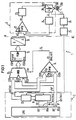
- a positioning device 1 as shown schematically in FIG. 1 in a block diagram, is suitable for carrying out a method for speed-controlled, translatory positioning of a read / write head 200 in relation to a rotating recording medium 21 with concentrically running information tracks 210.
- Positioning devices for data storage with rotating record carriers are generally known. It is therefore unnecessary to present and describe in detail the parts of such a device that are familiar to the person skilled in the art. Instead, for reasons of clarity and better understanding, only the functional blocks of the positioning device are shown in FIG. 1 which are essential for the invention.
- the positioning device for read / write heads 200 shown schematically in FIG. 1 is an electronically controlled mechanical device with an analog and digital component.
- the drive system can be designed as a linear or rotary positioner. In both cases, it has a permanent magnet (not shown) for generating a static magnetic field. In order to generate a variable magnetic field, a coil 201 of the drive system 20 is provided, through which a current i flows, which the power supply 23 supplies.
- the movement of the read / write head results from the mutual influence of the magnetic fields. Its actual speed vi is measured and by the speed keitswandler 24 converted into an electrical, the speed vi corresponding signal vi '. This signal is applied to an input of the comparator 22 and compared there with a speed signal vs' applied to a second input of the comparator. An error signal dv resulting from this is used to regulate the coil current.
- the speed signal vs' is generated digitally.
- the digital component of the positioning device shown on the left of the dividing line A ... B, has a central unit 10 which is connected to a track counter 11.
- the required number n of first signal lines X1... Xn depends on a number N of information tracks 210 on the recording medium 21. If the read / write head is now to be moved from a start track NS on the recording medium to a target track NZ, the the command necessary for this is passed on from a control unit of the central unit 10 to the track counter 11 via the signal lines X1 to Xn.
- the track counter is loaded with a target address xns at the beginning of the positioning process.
- the target address that is individual for each positioning process represents a target positioning distance nsz that the read / write head 200 travels from the start track NS to the destination track NZ.
- the track changes of the read / write head that are carried out are registered by a track following system 26 and converted by a position converter 25 into a track pulse spi corresponding to the track changes. With this track pulse, both the track counter and a one-memory flip-flop 12 are actuated in cycles and thus the content of the track counter that arises for each track change to the single-store flip-flop or simultaneously to the first switching inputs ES11 ... ES1n of a multiplexer 13 and to the first Comparison inputs EV11 ... EV1n of a comparator 14 passed on.
- the respective content of the track counter is composed of an actual address xni, which changes from one address to the other changing actual positioning distance niz for the read / write head 200 results.
- the actual positioning distance is determined from the difference between an actual track NI and the target track NZ. For each new actual track that the read / write head crosses, the counter reading of the track counter working in reverse mode is reduced by 1. At the end of the counting process, when the read / write head has reached the target track NZ, the counter is at zero.
- Both the multiplexer and the comparator each have second switching inputs ES21 ... ES2n or second comparison inputs EV21 ... EV2n, to which second signal lines Y1 ... Yn are connected.
- a comparison address ync generated by the central processing unit 10 is transmitted simultaneously to the multiplexer and to the comparator on these signal lines.
- the generated comparison address results from a positioning distance ncz, which indicates the distance between a transition track NC and the target track NZ.
- the transition track NC on the record carrier is the information track in which the read / write head changes from an acceleration phase v + to a braking phase v-.
- K1 9/16.
- K2 an additive constant K2 is also added. This takes into account the statistical relationship between the position of the transition track NC and the target positioning distance nsz. In many cases, however, it is sufficient for a still permissible, simplified description of the respective positioning process to set K2 to zero.
- the derived relationship is used as a basis for calculating the associated transition track for any desired positioning distance nsz in a computing unit of the central unit. Given the simplicity of this relationship, it does not appear necessary to describe the arithmetic unit and other components of the central processing unit necessary for the execution of arithmetic operations in detail. The implementation of such simple calculations with program-controlled systems is familiar to the person skilled in the art and is insignificant for understanding the invention.
- the value initially determined for each positioning process for the transition track NC is stored in a register (also not shown) and by indirect addressing output via the signal lines Y1 to Yn. Thus, the actual address xni is present at the first switching and comparison inputs of the multiplexer 13 or the comparator 14 and the comparison address ync is present at the second switching and comparison inputs.
- the comparator outputs a binary control signal dn with the signal states dn1 or dn0, with which the multiplexer is controlled.
- the comparison address ync at the second switching input ES21 ... ES2n of the multiplexer is switched through to a memory input ESP1 ... ESPn of a programmable read-only memory 15. If, on the other hand, the multiplexer is controlled by the control signal dn0, the actual address xni is switched through at the first switching input ES11 ... ES1n of the multiplexer. With the comparison address or actual address present at each of the memory inputs ESP1 ... ESPn of the programmable read-only memory, an individual maximum value vsmax ′ or a target speed value vs1 ...
- vsn is read from this and forwarded to a digital-to-analog converter 16 .
- the number of the desired speed values corresponds to the number N of information tracks 210 on the recording medium 21.
- the individual maximum value vsmax ′ is new for each positioning process.
- the respective maximum value is thus equal to the target speed value vs1 ... vsn, which corresponds to the transition track NC.
- the converted, analogized target speed signal vs' then serves, as already described, as a reference variable for the target / actual speed comparison on the comparator 22.
- the individual maximum value vsmax ' is applied to the control circuit 2. Only when the actual positioning distance niz is smaller than the distance ncz does the target speed value vs ′ on the comparator 22 change with each information track that is crossed by the read / write head 200.
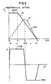
- FIG. 3 shows, for an "unregulated" positioning process, a set / actual speed curve with a corresponding coil current i.
- the illustration in FIG. 3 illustrates the physical processes in the control circuit 2.
- the coil is fed with a positive coil current i.
- a maximum setpoint speed value vsmax is applied to the input of the comparator up to a setpoint transition time tx, that is to say during the vsmax phase.
- Characteristic of the unregulated positioning process shown in FIG. 3 is the poor transient response of the measured actual speed profile vi 'with respect to the target speed profile vs' for times t greater than an actual transition time tc.
- the read / write head can no longer be positioned on the target track NZ due to the predefined setpoint speed profile vs' and the saturation property of the coil within an available braking time tz-tc.
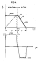
- FIG. 4 shows a setpoint-actual speed curve of a “regulated” positioning process.
- the vsmax phase is expanded and thus a much better transient response of the actual speed profile vi' to the target speed profile vs' is achieved.
- exact positioning of the read / write head over the information track NC is possible within the braking time tz-tc provided without the coil being driven into saturation at a current -imax.
- the method described has the advantage of requiring only one braking curve for different positioning distances when positioning a read / write head in relation to a record carrier. Compared to a method in which several braking curves are required, the method described requires a significantly smaller storage space. In addition, the method offers the possibility of using a single braking cure ve to perform the positioning of the read / write head with the greatest possible braking power. As already mentioned, this is noticeable in a shorter positioning time or access time. For the person skilled in the art, it is obvious from the above explanation of the exemplary embodiment of the invention that within the scope of the disclosed technical teaching, configurations are certainly possible which relate to any type of recording medium; eg magnetic, optical, magneto-optical storage disks, floppy discs.
- the recording media used for the described method have concentric information tracks.
- the method can also be used, for example, for pit structures arranged spirally on optical storage disks.
- the speed-controlled positioning of the read / write head within the scope of the disclosed technical teaching is completely micro-program-controlled, by also carrying out the address comparison and the address selection for the read-only memory using a micro-program.
Abstract
Description
Die Erfindung bezieht sich auf ein Verfahren gemäß dem Oberbegriff des Hauptanspruches.The invention relates to a method according to the preamble of the main claim.
Geschwindigkeitsgeregelte Positionierverfahren werden in unterschiedlichen technischen Gebieten, insbesondere auch bei Schreib-/Lesevorgängen in Datenspeichern eingesetzt. Ständig wachsende Speicherkapazität läßt sich nur mit erhöhter Speicherdichte erreichen, was sich z.B. in der erhöhten Anzahl von Informationsspuren pro Datenplatte ausdrückt. Deshalb muß bei Schreib- oder Lesevorgängen ein Schreib-/Lesekopf immer genauer positioniert werden. Im Interesse einer kleinen Zugriffszeit muß jedoch der Positioniervorgang so schnell wie möglich durchgeführt werden.Speed-controlled positioning methods are used in various technical fields, particularly also for read / write processes in data memories. Constantly increasing storage capacity can only be achieved with increased storage density, which is e.g. expresses in the increased number of information tracks per data disk. For this reason, a read / write head must always be positioned more precisely during write or read processes. In the interest of a short access time, however, the positioning process must be carried out as quickly as possible.
So ist ein wesentliches Leistungsmerkmal eines Plattenspeichers die Zeit, die zum Positionieren der Schreib-/Leseköpfe auf eine neue Spur benötigt wird. Eine minimale Positionierzeit bedingt aber, daß der Schreib-/Lesekopf bei unterschiedlichen Positionierdistanzen zunächst auf eine maximale Geschwindigkeit beschleunigt und danach innerhalb kürzester Zeit bis zu einer Zielspur abgebremst wird. Dies läßt sich über eine geschwindigkeitsabhängige Regelung beispielsweise des Motorstromes eines Positioniermotors erreichen, der den Schreib-/Lesekopf bewegt. Um den Schreib-/Lesekopf für die verschiedenen Positionierdistanzen über der Zielspur genau und schnell zu positionieren, ist es erforderlich, den zur Verfügung stehenden maximalen Motorstrom während der Beschleunigungs- und Bremsphase gut auszunutzen, ohne jedoch dabei einen Wert zu erreichen, bei dem dann der Schreib-/Lesekopf nicht mehr über der Zielspur angehalten werden kann.A key feature of disk storage is the time it takes to position the read / write heads on a new track. However, a minimum positioning time means that the read / write head accelerates to a maximum speed at different positioning distances and then brakes to a target track within a very short time. This can be achieved by means of a speed-dependent control, for example of the motor current of a positioning motor that moves the read / write head. In order to position the read / write head precisely and quickly for the various positioning distances above the target track, it is necessary to make good use of the maximum motor current available during the acceleration and braking phase, but without achieving a value at which the The read / write head can no longer be stopped above the target track.
Es ist daher ein geschwindigkeitsgeregeltes Positionierverfahren üblich, bei dem die Differenz einer gemessenen Ist-Geschwindigkeit zu einer vorgegebenen Soll-Geschwindigkeit den Strom des Positioniermotors regelt. Für große Positionierdistanzen läuft dabei der Positioniervorgang in drei Phasen ab. In der ersten Phase, einer Beschleunigungsphase, wird der Schreib-/Lesekopf mit maximalem Motorstrom auf eine maximale Soll-Geschwindigkeit vmax beschleunigt. In der zweiten Phase bleibt die Ist-Geschwindigkeit des Schreib-/Lesekopfes konstant. Die dritte Phase schließlich ist eine Bremsphase, bei der die Ist-Geschwindigkeit des Schreib-/Lesekopfes einer sich ändernden Soll-Geschwindigkeit angenähert wird. Die Soll-Geschwindigkeitswerte verringern sich dabei nach einer vorgegebenen Bremskurve solange, bis auf der Zielspur die Ist-Geschwindigkeit gleich Null ist.A speed-controlled positioning method is therefore customary, in which the difference between a measured actual speed and a predetermined target speed regulates the current of the positioning motor. For large positioning distances, the positioning process takes place in three phases. In the first phase, an acceleration phase, the read / write head is accelerated to a maximum target speed vmax with maximum motor current. In the second phase, the actual speed of the read / write head remains constant. Finally, the third phase is a braking phase, in which the actual speed of the read / write head is approximated to a changing target speed. The target speed values decrease according to a predetermined braking curve until the actual speed on the target track is zero.
Der Positioniervorgang, der in der beschriebenen Weise für größere Positionierdistanzen einwandfrei abläuft, erweist sich für kleine Positionierdistanzen als problematisch. So verkürzt sich bei abnehmenden Positionierdistanzen zunächst die konstante Phase immer mehr, bis schließlich die Beschleunigungsphase unmittelbar in die Bremsphase übergeht, wobei der maximale Soll-Geschwindigkeitswert vmax nicht mehr erreicht wird. Bei einem direkten Übergang von der Beschleunigungs- in die Bremsphase muß aber die Stromrichtung im Positioniermotor bei hoher Leistung unmittelbar umgepolt werden. Die technisch bedingte begrenzte Stromanstiegsgeschwindigkeit, sowie Einschwingvorgänge aufgrund der Unstetigkeitsstelle der Regelcharakteristik haben größere Differenzen voll Soll- und Ist-Geschwindigkeit zur Folge. Bei einer für alle Positionierdistanzen identischen Bremskurve kann das Nachziehverhalten der Regelung den Motorstrom in die Sättigung steuern und dann ein kontrolliertes Positionieren des Schreib-/Lesekopfes vereiteln.The positioning process, which runs perfectly in the manner described for larger positioning distances, proves to be problematic for small positioning distances. Thus, with decreasing positioning distances, the constant phase initially shortens more and more, until finally the acceleration phase changes directly into the braking phase, with the maximum target speed value vmax no longer being reached. In the case of a direct transition from the acceleration to the braking phase, however, the direction of current in the positioning motor must be reversed at high power. The technically-related limited current rise rate, as well as settling processes due to the discontinuity of the control characteristic result in larger differences between the set and actual speeds. With a braking curve that is identical for all positioning distances, the trailing behavior of the control system can steer the motor current into saturation and then prevent a controlled positioning of the read / write head.
Um dieses Problem zu vermeiden, könnte man eine einzige Bremskurve mit verminderter Bremsleistung verwenden. Die Bremskurve muß dann so ausgelegt sein, daß bei kürzeren Positionierdistanzen keine Sättigung des Motorstroms in der Bremsphase eintritt. Nachteilig ist dabei jedoch die verminderte Bremsleistung bei längeren Positionierdistanzen und eine damit sich zwangsläufig ergebende Erhöhung der Positionierzeit.To avoid this problem, a single braking curve with reduced braking power could be used. The The braking curve must then be designed so that the motor current does not saturate in the braking phase at shorter positioning distances. However, the disadvantage of this is the reduced braking power with longer positioning distances and a consequent increase in the positioning time.
Eine weitere Möglichkeit bestünde darin, mehrere Bremskurven für unterschiedliche Positionierdistanzen zu verwenden. Dieses Verfahren wäre jedoch systematisch bedingt aufwendig. Je nach Positionierdistanz wäre die für diese Distanz geeignete Bremskurve auszuwählen. Ein weiterer Nachteil wäre der erhöhte Speicherplatzbedarf für die Bremskurven.Another option would be to use multiple braking curves for different positioning distances. This method would, however, be systematically complex. Depending on the positioning distance, the braking curve suitable for this distance should be selected. Another disadvantage would be the increased storage space required for the braking curves.
Aus der DE-C 25 01 792 ist weiterhin eine Anordnung zum Regeln der Verschiebung und Positionierung eines translatorisch beweglichen Systems bekannt, die auf einer Zweiphasenregelanordnung beruht. Eine Umkehrsteuereinrichtung erlaubt das translatorisch bewegliche System während einer ersten Bewegungsphase im freien Betrieb bzw. ungeregelt zu beschleunigen. Mit Hilfe eines Nullkomparators wird ein Umkehrpunkt festlegt, bei dem die Beschleunigungsphase in eine zweite Bewegungsphase, die Bremsphase übergeht. Durch die Umkehrsteuereinrichtung wird in der Beschleunigungsphase weiterhin ein erster Regelkreis geschlossen und dadurch aus einem Soll-Ist-Geschwindigkeitsvergleich ein Regelsignal gewonnen. Dieses wird beim Erreichen des Umkehrpunktes zum Nachregeln der Soll-Geschwindigkeit einem Generator zugeführt. Die so nachgeregelte Soll-Geschwindigkeit wird in einem zweiten Regelkreis mit der Ist-Geschwindigkeit während der Bremsphase verglichen.From DE-C 25 01 792 an arrangement for regulating the displacement and positioning of a translationally movable system is also known, which is based on a two-phase control arrangement. A reversing control device allows the translationally movable system to be accelerated in free operation or uncontrolled during a first movement phase. With the help of a zero comparator, a reversal point is determined at which the acceleration phase changes into a second movement phase, the braking phase. In the acceleration phase, the reversing control device continues to close a first control loop, thereby obtaining a control signal from a target / actual speed comparison. When the reversal point is reached, this is fed to a generator to readjust the setpoint speed. The readjusted target speed is compared in a second control loop with the actual speed during the braking phase.
Bei der bekannten Anordnung wird somit die Flankensteilheit der Bremskurve für jeden Positioniervorgang geändert, um auf diese Weise zu erreichen, daß das translatorisch bewegliche System über die Zielspur nicht hinausfährt. Nachteilig ist es jedoch, daß die Anordnung zum Regeln der Positionie rung bzw. Verschiebung eines translatorisch beweglichen Systems, sehr aufwendig gestaltet ist. So sind z. B. mehrere Schalter notwendig, um die zwei Regelkreise während der beiden Bewegungsphasen gesteuert durch die ebenfalls sehr aufwendig ausgestaltete Umkehrsteuereinrichtung geöffnet bzw. geschlossen zu halten. Die der bekannten Anordnung als Regelungsprinzip zugrundegelegten Zweiphasenregelung ist hinsichtlich einer minimalen Positionierzeit zwar recht vorteilhaft, jedoch werden dafür regelungstechnische Probleme in Kauf genommen. Diese ergeben sich insbesondere aus dem abrupten Übergang zweier Bewegungsphasen mit entgegengesetzter Wirkung auf das translatorisch bewegliche System.In the known arrangement, the steepness of the edge of the braking curve is therefore changed for each positioning operation in order to ensure that the translationally movable system does not move beyond the target track. However, it is disadvantageous that the arrangement for regulating the position tion or displacement of a translationally movable system, is very expensive. So z. B. several switches necessary to keep the two control loops open or closed during the two movement phases controlled by the also very complex designed reversing control device. The two-phase control on which the known arrangement is based as a control principle is quite advantageous with regard to a minimal positioning time, but control engineering problems are accepted for this. These result in particular from the abrupt transition of two movement phases with the opposite effect on the translationally movable system.
Der vorliegenden Erfindung liegt daher die Aufgabe zugrunde, ein Verfahren der eingangs genannten Art zu schaffen, mit dem ein Schreib-/Lesekopf ungeachtet verschiedener Positionierdistanzen innerhalb kürzester Zeit und ohne regeltechnische Probleme an einen lokalen Ort auf einem Aufzeichnungsträger exakt positioniert wird.The present invention is therefore based on the object of providing a method of the type mentioned at the outset with which a read / write head is positioned precisely on a recording medium in a very short time and without control problems, regardless of different positioning distances.
Diese Aufgabe wird erfindungsgemäß bei einem Verfahren der eingangs genannten Art durch die im Kennzeichen des Hauptanspruches beschriebenen Merkmale gelöst. Dabei wird bei jeder Positionierdistanz, die ein Schreib-/Lesekopf während eines Positioniervorganges zurücklegt, der Positioniervorgang in eine Bremsphase, eine sich daran anschließende kurze Übergangsphase und eine bei einer Übergangsspur einsetzende Bremsphase unterteilt. Mit einer Dreiphasenregelung der genannten Art lassen sich die beschriebenen Mängel bekannter Lösungen vermeiden bzw. beseitigen. Die Lösung zeichnet sich insbesondere dadurch aus, daß für das geschwindigkeitsgeregelte Positionieren des Schreib-/Lesekopfes, ungeachtet der jeweiligen Positionierdistanz, nur eine einzige gespeicherte Bremskurve benötigt wird, aus der Soll-Geschwindigkeitswerte für einen Soll-Ist-Geschwindigkeitsvergleich zur Geschwindigkeitsregelung entnommen werden. Um ein Adressieren und Auslesen der gespeicherten Soll-Geschwindigkeitswerte zu ermöglichen, wird unabhängig von dem jeweiligen Bewegungszustand des Schreib-/Lesekopfes bei jedem Spurwechsel ein Adressenvergleich zwischen einer Vergleichs- und einer Ist-Adresse des Schreib-/Lesekopfes vorgenommen. Die für diesen Vergleich notwendige Vergleichsadresse ergibt sich aus der Übergangsspur, deren Distanz beispielsweise zur Zielspur bei jeder Positionierdistanz einen anderen Wert annimmt. Bei dieser Zählweise ist die Ist-Adresse die Distanz der aktuellen Position des Schreib-/Lesekopfes zur Zielspur. Je nachdem, ob die Ist-Adresse größer, gleich bzw. kleiner als die Vergleichsadresse ist, wird entweder ein bestimmter, unveränderlicher Soll-Geschwindigkeitswert aus der Bremskurve mit der Ist-Geschwindigkeit des Schreib-/Lesekopfes verglichen oder ein mit jedem Spurwechsel abnehmender Soll-Geschwindigkeitswert aus der Bremskurve mit der Ist-Geschwindigkeit verglichen. Auf diese Weise wird die Positionierzeit mit einem Verfahren minimiert, bei dem der regelungstechnische Aufwand für seine Durchführung dennoch so klein wie möglich gehalten wird.This object is achieved in a method of the type mentioned by the features described in the characterizing part of the main claim. For each positioning distance that a read / write head travels during a positioning process, the positioning process is divided into a braking phase, a short transition phase that follows, and a braking phase that starts at a transition track. With a three-phase control of the type mentioned, the described shortcomings of known solutions can be avoided or eliminated. The solution is characterized in particular by the fact that for the speed-controlled positioning of the read / write head, regardless of the respective positioning distance, only a single stored braking curve is required, from which the target speed values for a target-actual speed comparison for speed control are taken. To address and read out the stored To enable target speed values, an address comparison between a comparison address and an actual address of the read / write head is carried out with each lane change, regardless of the respective movement state of the read / write head. The comparison address necessary for this comparison results from the transition track, the distance of which, for example, to the target track assumes a different value at each positioning distance. With this method of counting, the actual address is the distance of the current position of the read / write head to the target track. Depending on whether the actual address is greater, the same or less than the comparison address, either a specific, unchangeable setpoint speed value from the braking curve is compared with the actual speed of the read / write head, or a setpoint value that decreases with each lane change Speed value from the braking curve compared with the actual speed. In this way, the positioning time is minimized with a method in which the control engineering effort for its implementation is nevertheless kept as small as possible.
Weiterbildungen der Erfindung werden in einer nachfolgenden Beschreibung eines Ausführungsbeispieles näher erläutert, wobei auf die Zeichnung Bezug genommen wird:
- FIG 1 ein Blockdiagramm einer Geschwindigkeitsregelung für einen Schreib-/Lesekopf,
- FIG 2 einen Soll-Geschwindigkeits-Zeitverlauf mit einer hilfsweise eingezeichneten, spurbezogene Abzissenachse,
- FIG 3 ein Geschwindigkeits-Zeitdiagramm eines "ungeregelten" Schreib-/Lesekopfes mit korrespondierendem zeitlichem Spulenstromverlauf,
- FIG 4 ein Geschwindigkeits-Zeitdiagramm eines "geregelten" Schreib-/Lesekopfes mit korrespondierendem zeitlichem Spulenstromverlauf.
- 1 shows a block diagram of a speed control for a read / write head,
- 2 shows a target speed-time curve with an auxiliary, track-related abscissa axis,
- 3 shows a speed-time diagram of an "unregulated" read / write head with a corresponding temporal coil current profile,
- 4 shows a speed-time diagram of a "regulated" read / write head with a corresponding temporal coil current profile.
Zum Durchführen eines Verfahrens zum geschwindigkeitsgeregelten, translatorischen Positionieren eines Schreib-/Lesekopfes 200 in bezug auf einen rotierenden Aufzeichnungsträger 21 mit konzentrisch verlaufenden Informationsspuren 210 ist eine Positioniereinrichtung 1 geeignet, wie sie in FIG 1 in einem Blockdiagramm schematisch dargestellt ist. Positioniereinrichtungen für Datenspeicher mit rotierenden Aufzeichnungsträgern sind allgemein bekannt. Es ist daher überflüssig, die dem Fachmann durchaus geläufigen Teile einer derartigen Einrichtung in allen Einzelheiten darzustellen und zu beschreiben. Stattdessen sind in FIG 1 aus Gründen der Übersichtlichkeit und des besseren Verständnisses nur die Funktionsblöcke der Positioniereinrichtung gezeigt, die für die Erfindung wesentlich sind.A positioning device 1, as shown schematically in FIG. 1 in a block diagram, is suitable for carrying out a method for speed-controlled, translatory positioning of a read / write
Die in FIG 1 schematisch dargestellte Positioniereinrichtung für Schreib-/Leseköpfe 200 ist eine elektronisch gesteuerte mechanische Einrichtung mit einer analogen und digitalen Komponente. Die analoge Komponente in FIG 1, rechts einer Trennungslinie A...B dargestellt, abstrahiert sich zu einem elektronischen Regelkreis 2, bestehend aus einem Antriebssystem 20, mit dem die Schreib-/Leseköpfe 200 translatorisch bewegt werden, einem analogen Komparator 22, einer Stromversorgung 23 für das Antriebssystem und einem Geschwindigkeitswandler 24.The positioning device for read / write
Das Antriebssystem kann als Linear- oder Drehpositionierer ausgebildet sein. Es weist in beiden Fällen einen nicht dargestellten Permanentmagneten zum Erzeugen eines statischen Magnetfeldes auf. Zur Erzeugen eines veränderlichen magnetischen Feldes ist eine Spule 201 des Antriebssystems 20 vorgesehen, die von einem Strom i durchflossen wird, den die Stromversorgung 23 liefert.The drive system can be designed as a linear or rotary positioner. In both cases, it has a permanent magnet (not shown) for generating a static magnetic field. In order to generate a variable magnetic field, a coil 201 of the drive system 20 is provided, through which a current i flows, which the power supply 23 supplies.
Aus der gegenseitigen Beeinflussung der Magnetfleder resultiert die Bewegung des Schreib-/Lesekopfes. Seine Ist-Geschwindigkeit vi wird gemessen und durch den Geschwindig keitswandler 24 in ein elektrisches, der Geschwindigkeit vi entsprechendes Signal vi′ umgeformt. Dieses Signal wird an einen Eingang des Komparators 22 gelegt und dort mit einem an einem zweiten Eingang des Komparators angelegten Geschwindigkeitssignal vs′ verglichen. Ein sich hieraus ergebendes Fehlersignal dv wird dazu benutzt, den Spulenstrom zu regeln.The movement of the read / write head results from the mutual influence of the magnetic fields. Its actual speed vi is measured and by the
Das Geschwindigkeitssignal vs′ wird auf digitalem Wege generiert. Dazu weist die digitale Komponente der Positioniereinrichtung, links der Trennungslinie A...B dargestellt, eine Zentraleinheit 10 auf, die mit einem Spurzähler 11 verbunden ist. Die benötigte Anzahl n von ersten Signalleitungen X1...Xn ist abhängig von einer Anzahl N von Informationsspuren 210 auf dem Aufzeichnungsträger 21. Soll nun der Schreib-/Lesekopf von einer Startspur NS auf dem Aufzeichnungsträger zu einer Zielspur NZ bewegt werden, so wird der hierfür notwendige Befehl von einem Steuerwerk der Zentraleinheit 10 über die Signalleitungen X1 bis Xn an den Spurzähler 11 weitergegeben. Der Spurzähler wird dazu zu Beginn des Positioniervorganges mit einer Soll-Adresse xns geladen. Die für jeden Positioniervorgang individuelle Soll-Adresse repräsentiert eine Soll-Positionierdistanz nsz, die der Schreib-/Lesekopf 200 von der Startspur NS bis zur Zielspur NZ zurücklegt. Die dabei vollzogenen Spurwechsel des Schreib-/Lesekopfes werden von einem Spurfolgesystem 26 registriert und von einem Positionswandler 25 in einen jeweils zu den Spurwechseln korrespondierenden Spurimpuls spi umgeformt. Mit diesem Spurimpuls wird sowohl der Spurzähler als auch eine Einspeicher-Kippschaltung 12 taktmäßig angesteuert und dadurch der sich für jeden Spurwechsel neu ergebende Inhalt des Spurzählers an die Einspeicher-Kippschaltung bzw. gleichzeitig an erste Schalteingänge ES11...ES1n eines Multiplexers 13 und an erste Vergleichseingänge EV11...EV1n eines Vergleichers 14 weitergegeben.The speed signal vs' is generated digitally. For this purpose, the digital component of the positioning device, shown on the left of the dividing line A ... B, has a central unit 10 which is connected to a track counter 11. The required number n of first signal lines X1... Xn depends on a number N of information tracks 210 on the recording medium 21. If the read / write head is now to be moved from a start track NS on the recording medium to a target track NZ, the the command necessary for this is passed on from a control unit of the central unit 10 to the track counter 11 via the signal lines X1 to Xn. For this purpose, the track counter is loaded with a target address xns at the beginning of the positioning process. The target address that is individual for each positioning process represents a target positioning distance nsz that the read /
Der jeweilige Inhalt des Spurzählers setzt sich aus einer Ist-Adresse xni zusammen, die aus einer sich jeweils verän dernden Ist-Positionierdistanz niz für den Schreib-/Lesekopf 200 resultiert. Die Ist-Positionierdistanz bestimmt sich dabei aus der Differenz zwischen einer Ist-Spur NI und der Zielspur NZ. Für jede neue Ist-Spur, die der Schreib-/Lesekopf überquert, wird abschließend der Zählerstand des im Rückwärtsbetrieb arbeitenden Spurzählers um 1 verringert. Am Ende des Zählvorganges, wenn der Schreib-/Lesekopf die Zielspur NZ erreicht hat, steht somit der Zähler auf Null.The respective content of the track counter is composed of an actual address xni, which changes from one address to the other changing actual positioning distance niz for the read /
Sowohl der Multiplexer als auch der Vergleicher weisen jeweils noch zweite Schalteingänge ES21...ES2n bzw. zweite Vergleichseingänge EV21...EV2n auf, an die zweite Signalleitungen Y1...Yn angeschlossen sind. Auf diesen Signalleitungen wird eine von der Zentraleinheit 10 generierte Vergleichsadresse ync gleichzeitig an den Multiplexer und an den Vergleicher übertragen. Die generierte Vergleichsadresse ergibt sich dabei aus einer Positionierdistanz ncz, die die Distanz zwischen einer Übergangsspur NC und der Zielspur NZ angibt. Die Übergangsspur NC auf dem Aufzeichnungsträger ist die Informationsspur, bei der der Schreib-/Lesekopf von einer Beschleunigungsphase v+ in eine Bremsphase v- übergeht.Both the multiplexer and the comparator each have second switching inputs ES21 ... ES2n or second comparison inputs EV21 ... EV2n, to which second signal lines Y1 ... Yn are connected. A comparison address ync generated by the central processing unit 10 is transmitted simultaneously to the multiplexer and to the comparator on these signal lines. The generated comparison address results from a positioning distance ncz, which indicates the distance between a transition track NC and the target track NZ. The transition track NC on the record carrier is the information track in which the read / write head changes from an acceleration phase v + to a braking phase v-.
Der Übergang von der Beschleunigungsphase in die Bremsphase erfolgt zu keinem festgelegten Zeitpunkt, sondern vielmehr an einem Punkt, der von der Soll-Positionierdistanz nsz abhängt. So haben kleinere Soll-Positionierdistanzen eine andere Übergangsspur NC als größere Distanzen. Diese Abhängigkeit zwischen den verschiedenen Soll-Positionierdistanzen und der jeweiligen Übergangsspur, bei der der Schreib-/Lesekopf von der Beschleunigungs- in die Bremsphase übertritt, läßt sich aus folgenden physikalischen Überlegungen ableiten. Für eine beliebig vorgegebene Soll-Positionierdistanz ist es aus der Energiebilanz heraus zweckmäßig, den Schreib-/Lesekopf bis zur Hälfte der Distanz zu beschleunigen und danach wieder kontinuierlich abzubremsen. Vereinfachend erscheint es zulässig, einen linear-proportionalen Zusammenhang mit einer Proportionalitätskonstanten K1 anzusetzen, die im einfachsten Fall in etwa den Wert 0,5 annimmt. Diese Annahmen lassen sich verifizieren, indem man für alle anderen denkbaren Soll-Positionierdistanzen die tatsächlichen Ergebnisse auswertet. Die durch Versuche bestätigte Gesetzmäßigkeit führt im allgemeinen Fall zu folgender Beziehung:
(1) NC = K1 x nsz + K2
The transition from the acceleration phase to the braking phase does not take place at a fixed point in time, but rather at a point that depends on the target positioning distance nsz. Smaller target positioning distances have a different transition track NC than larger distances. This dependency between the various target positioning distances and the respective transition track, in which the read / write head changes from the acceleration to the braking phase, can be derived from the following physical considerations. For an arbitrarily specified target positioning distance, it is expedient from the energy balance to accelerate the read / write head up to half the distance and then brake it again continuously. To simplify matters, it seems permissible to use a linear proportional one To be used in connection with a proportionality constant K1, which in the simplest case assumes approximately the value 0.5. These assumptions can be verified by evaluating the actual results for all other possible target positioning distances. The regularity confirmed by tests leads in the general case to the following relationship:
(1) NC = K1 x nsz + K2
Im Interesse einer möglichst minimalen Positionierzeit ist es jedoch wünschenswert, den Bremsvorgang so kurz wie möglich zu halten, mit der Nebenbedingung, den Schreib-/Lesekopf trotzdem genau positionieren zu können. Um diesen Sachverhalt Rechnung zu tragen, wird beispielsweise für K1 ein Wert gewählt, der größer ist als 0,5, vorzugsweise K1 = 9/16. In der Beziehung (1) ist weiterhin eine additive Konstante K2 hinzugeführt. Diese berücksichtigt den statistischen Zusammenhang zwischen der Lage der Übergangsspur NC und der Soll-Positionierdistanz nsz. In vielen Fällen ist es jedoch für eine noch zulässige, vereinfachte Beschreibung des jeweiligen Positioniervorganges ausreichend, K2 zu Null zu setzen.In the interest of the shortest possible positioning time, however, it is desirable to keep the braking process as short as possible, with the additional condition that the read / write head can still be positioned exactly. To take this into account, a value is selected for K1, for example, that is greater than 0.5, preferably K1 = 9/16. In relation (1), an additive constant K2 is also added. This takes into account the statistical relationship between the position of the transition track NC and the target positioning distance nsz. In many cases, however, it is sufficient for a still permissible, simplified description of the respective positioning process to set K2 to zero.
Die hergeleitete Beziehung wird zugrundegelegt, um in einem Rechenwerk der Zentraleinheit für jede beliebige Soll-Positionierdistanz nsz die zugeordnete Übergangsspur zu berechnen. Bei der Einfachheit dieser Beziehung erscheint es nicht erforderlich, das Rechenwerk und weitere, für die Ausführung von arithmetischen Operationen notwendige Bestandteile der Zentraleinheit im einzelnen zu beschreiben. Die Durchführung derartiger einfacher Berechnungen mit programmgesteuerten Anlagen ist dem Fachmann geläufig und für das Verständnis der Erfindung unwesentlich. Der für jeden Positioniervorgang zunächst ermittelte Wert für die Übergangsspur NC wird in einem ebenfalls nicht dargestellten Register abgespeichert und durch indirekte Adressierung über die Signalleitungen Y1 bis Yn ausgegeben. Somit liegt an den ersten Schalt- und Vergleichseingängen des Multiplexers 13 bzw. des Vergleichers 14 die Ist-Adresse xni und an den zweiten Schalt- und Vergleichseingängen die Vergleichsadresse ync an.The derived relationship is used as a basis for calculating the associated transition track for any desired positioning distance nsz in a computing unit of the central unit. Given the simplicity of this relationship, it does not appear necessary to describe the arithmetic unit and other components of the central processing unit necessary for the execution of arithmetic operations in detail. The implementation of such simple calculations with program-controlled systems is familiar to the person skilled in the art and is insignificant for understanding the invention. The value initially determined for each positioning process for the transition track NC is stored in a register (also not shown) and by indirect addressing output via the signal lines Y1 to Yn. Thus, the actual address xni is present at the first switching and comparison inputs of the
Je nachdem, ob die Ist-Adresse größer oder gleich bzw. kleiner als die Vergleichsadresse ist, wird von dem Vergleicher ein binäres Steuersignal dn mit den Signalzuständen dn1 bzw. dn0 ausgegeben, mit dem der Multiplexer gesteuert wird.Depending on whether the actual address is greater than or equal to or smaller than the comparison address, the comparator outputs a binary control signal dn with the signal states dn1 or dn0, with which the multiplexer is controlled.
Liegt nun das Steuersignal dn1 an dem Multiplexer an, so wird die Vergleichsadresse ync am zweiten Schalteingang ES21...ES2n des Multiplexers an einen Speichereingang ESP1 ...ESPn eines programmierbaren Festwertspeichers 15 durchgeschaltet. Wird hingegen der Multiplexer von dem Steuersignal dn0 gesteuert, so wird die Ist-Adresse xni am ersten Schalteingang ES11...ES1n des Multiplexers durchgeschaltet. Mit der jeweils an Speichereingänge ESP1...ESPn des programmierbaren Festwertspeichers anliegenden Vergleichsadresesse bzw. Ist-Adresse wird aus diesem ein individueller Maximalwert vsmax′ bzw. ein Soll-Geschwindigkeitswert vs1...vsn ausgelesen und an einen Digital-Analog-Wandler 16 weitergegeben. Die Anzahl der Soll-Geschwindigkeitswerte entspricht dabei im Maximalfall der Anzahl N der Informationsspuren 210 auf dem Aufzeichnungsträger 21. Der individuelle Maximalwert vsmax′ ergibt sich für jeden Positioniervorgang neu. So ist der jeweilige Maximalwert gleich dem Soll-Geschwindigkeitswert vs1...vsn, der zu der Übergangsspur NC korrespondiert. Das umgewandelte, analogisierte Soll-Geschwindigkeitssignal vs′ dient anschließend, wie bereits beschrieben, als Bezugsgröße für den Soll-Ist-Geschwindigkeitsvergleich am Komparator 22.If the control signal dn1 is now present at the multiplexer, the comparison address ync at the second switching input ES21 ... ES2n of the multiplexer is switched through to a memory input ESP1 ... ESPn of a programmable read-
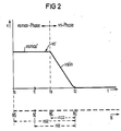
FIG 2 zeigt einen Soll-Geschwindigkeits-Zeitverlauf vs, für den hilfsweise zum Verdeutlichen des Zusammenhanges zwischen der Übergangsspur NC und der Soll-Positionierdistanz nsz auf einer zweiten, mit unterbrochenden Linien gezeichneten Abzissenachse die Anzahl N der Informationsspuren des Aufzeichnungsträgers aufgetragen sind. Der Verlauf, wie er nach dem Umwandeln durch den DA-Wandler vorliegt, ist mit seinen diskreten Werten pro Informationsspur in dem programmierbaren Festwertspeicher 15 gespeichert. Der konstante Anteil des vs′-Verlaufes entspricht dabei dem individuellen Maximalwert vsmax′, während der linear abfallende Teil des vs′-Verlaufes, im folgenden als Bremskurve vslin bezeichnet, sich aus den diskreten Geschwindigkeitswerten zusammensetzt, die kleiner sind als der individuelle Maximalwert. Für die in FIG 2 eingezeichnete Soll-Positionierdistanz nsz ist der Übergang von einer vsmax-Phase zu einer vs-Phase bei der Übergangsspur NC.2 shows a target speed-time profile vs, for the alternative to clarify the relationship between the transition track NC and the target positioning distance nsz the number N of information tracks of the record carrier are plotted on a second axis of abscissa drawn with interrupted lines. The course as it is after the conversion by the DA converter is stored with its discrete values per information track in the programmable read-
So wird aufgrund der vorangegangenen Erläuterungen zu FIG 1 für die Ist-Positionierdistanz niz, die größer gleich als die Distanz ncz zwischen der Übergangsspur NC und der Zielspur NZ ist, der individuelle Maximalwert vsmax′ an den Regelkreis 2 gelegt. Erst wenn die Ist-Positionierdistanz niz kleiner der Distanz ncz ist, ändert sich mit jeder Informationsspur, die von dem Schreib-/Lesekopf 200 überquert wird, der Soll-Geschwindigkeitswert vs′ an dem Komparator 22.Thus, on the basis of the preceding explanations for FIG. 1, for the actual positioning distance niz, which is greater than or equal to the distance ncz between the transition track NC and the target track NZ, the individual maximum value vsmax 'is applied to the control circuit 2. Only when the actual positioning distance niz is smaller than the distance ncz does the target speed value vs ′ on the comparator 22 change with each information track that is crossed by the read /
FIG 3 zeigt für einen "ungeregelten" Positioniervorgang einen zeitlichen Soll-/Ist-Geschwindigkeitsverlauf mit korrespondierendem Spulenstrom i. Die Darstellung in FIG 3 veranschaulicht die physikalischen Vorgänge in dem Regelkreis 2. Zu einem Startzeitpunkt ts, bei den sich der Schreib-/Lesekopf 200 über der Startspur NS befindet, wird die Spule mit einem positiven Spulenstrom i gespeist. Zur gleichen Zeit, in der der Schreib-/Lesekopf beschleunigt wird, wird bis zu einem Soll-Übergangszeitpunkt tx, also während der vsmax-Phase, ein maximaler Soll-Geschwindigkeitswert vsmax an den Eingang des Komparators gelegt.3 shows, for an "unregulated" positioning process, a set / actual speed curve with a corresponding coil current i. The illustration in FIG. 3 illustrates the physical processes in the control circuit 2. At a starting point in time ts at which the read /
Kennzeichnend für den in FIG 3 dargestellten, ungeregelten Positioniervorgang ist das schlechte Einschwingverhalten des gemessenen Ist-Geschwindigkeitsverlaufes vi′ bezogen auf den Soll-Geschwindigkeitsverlauf vs′ für Zeiten t größer als einem Ist-Übergangszeitpunkt tc. So kann der Schreib-/ Lesekopf aufgrund des vorgegebenen Soll-Geschwindigkeitsverlaufes vs′ und der Sättigungseigenschaft der Spule innerhalb einer zur Verfügung stehenden Bremszeit tz-tc nicht mehr auf die Zielspur NZ positioniert werden.Characteristic of the unregulated positioning process shown in FIG. 3 is the poor transient response of the measured actual speed profile vi 'with respect to the target speed profile vs' for times t greater than an actual transition time tc. For example, the read / write head can no longer be positioned on the target track NZ due to the predefined setpoint speed profile vs' and the saturation property of the coil within an available braking time tz-tc.
Im Gegensatz zu FIG 3 zeigt die FIG 4 einen zeitlichen Soll-Ist-Geschwindigkeitsverlauf von einem "geregelten" Positioniervorgang. Der wesentliche Unterschied zum ungeregelten Fall, wie er in FIG 3 dargestellt ist, besteht darin, daß die vsmax-Phase bis zu dem Ist-Übergangszeitpunkt tc anhält und somit der Dauer der Beschleunigungsphase v+ und einer Übergangsphase v= des Schreib-/Lesekopfes 200 identisch ist. Gleiches gilt in diesem Fall für die vs-Phase und die Bremsphase v-. Durch das Verwenden des individuellen Maximalwertes vsmax′ statt des maximalen Soll-Geschwindigkeitswertes vsmax für die Geschwindigkeitsregelung wird die vsmax-Phase ausgedehnt und damit ein weitaus besseres Einschwingverhalten des Ist-Geschwindigkeitsverlaufes vi′ an den Soll-Geschwindigkeitsverlauf vs′ erzielt. Außerdem ist ein genaues Positionieren des Schreib-/Lesekopfes über der Informationsspur NC innerhalb der dafür vorgesehenen Bremszeit tz-tc möglich, ohne daß die Spule bei einem Strom -imax in die Sättigung getrieben wird.In contrast to FIG. 3, FIG. 4 shows a setpoint-actual speed curve of a “regulated” positioning process. The main difference from the unregulated case, as shown in FIG. 3, is that the vsmax phase lasts until the actual transition time tc and thus the duration of the acceleration phase v + and a transition phase v = of the read /
Das beschriebene Verfahren hat den Vorteil, für unterschiedliche Positionierdistanzen beim Positionieren eines Schreib-/Lesekopfes in bezug auf einen Aufzeichnungsträger nur eine Bremskurve zu erfordern. Gegenüber einem Verfahren, bei dem mehrere Bremskurven benötigt werden, bedarf es bei dem beschriebenen Verfahren eines wesentlich geringeren Speicherplatzes. Darüber hinaus bietet das Verfahren die Möglichkeit, trotz der Verwendung einer einzigen Bremskur ve, das Positionieren des Schreib-/Lesekopfes mit einer größtmöglichen Bremsleistung durchzuführen. Dies macht sich, wie bereits erwähnt, in einer kleineren Positionierzeit bzw. Zugriffszeit bemerkbar. Für den Fachmann ist es aus der vorstehenden Erläuterung des Ausführungsbeispieles der Erfindung naheliegend, daß im Rahmen der offenbarten technischen Lehre durchaus Ausgestaltungen möglich sind, die sich auf jegliche Arten von Aufzeichnungsträgern beziehen; z.B. magnetische, optische, magneto-optische Speicherplatten, Floppy-Discs. So ist es insbesondere nicht erforderlich, daß die verwendeten Aufzeichnungsträger für das beschriebene Verfahren konzentrische Informationsspuren aufweisen. Das Verfahren läßt sich beispielsweise auch für spiralförmig angeordnete Pit-Strukturen auf optische Speicherplatten anwenden. Neben den genannten Ausgestaltungen ist es für den Fachmann aber gleichfalls vorstellbar, daß das geschwindigkeitsgeregelte Positionieren des Schreib-/Lesekopfes im Rahmen der offenbarten technischen Lehre vollständig mikroprogrammgesteuert abläuft, indem auch der Adressenvergleich und die Adressenauswahl für den Festwertspeicher mit Hilfe eines Mikroprogrammes durchgeführt wird.The method described has the advantage of requiring only one braking curve for different positioning distances when positioning a read / write head in relation to a record carrier. Compared to a method in which several braking curves are required, the method described requires a significantly smaller storage space. In addition, the method offers the possibility of using a single braking cure ve to perform the positioning of the read / write head with the greatest possible braking power. As already mentioned, this is noticeable in a shorter positioning time or access time. For the person skilled in the art, it is obvious from the above explanation of the exemplary embodiment of the invention that within the scope of the disclosed technical teaching, configurations are certainly possible which relate to any type of recording medium; eg magnetic, optical, magneto-optical storage disks, floppy discs. In particular, it is not necessary that the recording media used for the described method have concentric information tracks. The method can also be used, for example, for pit structures arranged spirally on optical storage disks. In addition to the above-mentioned configurations, it is also conceivable for the person skilled in the art that the speed-controlled positioning of the read / write head within the scope of the disclosed technical teaching is completely micro-program-controlled, by also carrying out the address comparison and the address selection for the read-only memory using a micro-program.
Claims (2)
Applications Claiming Priority (2)
| Application Number | Priority Date | Filing Date | Title |
|---|---|---|---|
| DE3743391 | 1987-12-21 | ||
| DE3743391 | 1987-12-21 |
Publications (1)
| Publication Number | Publication Date |
|---|---|
| EP0321886A1 true EP0321886A1 (en) | 1989-06-28 |
Family
ID=6343183
Family Applications (1)
| Application Number | Title | Priority Date | Filing Date |
|---|---|---|---|
| EP88121167A Withdrawn EP0321886A1 (en) | 1987-12-21 | 1988-12-16 | Method of speed-controlled positioning of a read/write head with regard to a rotating recording medium |
Country Status (1)
| Country | Link |
|---|---|
| EP (1) | EP0321886A1 (en) |
Cited By (1)
| Publication number | Priority date | Publication date | Assignee | Title |
|---|---|---|---|---|
| EP0356939A1 (en) * | 1988-08-25 | 1990-03-07 | Sharp Kabushiki Kaisha | Device for controlling an access operation of an information recording and reproducing device |
Citations (7)
| Publication number | Priority date | Publication date | Assignee | Title |
|---|---|---|---|---|
| FR2125852A5 (en) * | 1971-02-15 | 1972-09-29 | Ibm | |
| US3729668A (en) * | 1970-06-26 | 1973-04-24 | Honeywell Bull Soc Ind | Aparatus for controlling the displacement of an object between any two points |
| FR2172733A5 (en) * | 1972-02-18 | 1973-09-28 | Philips Nv | |
| FR2258661A1 (en) * | 1974-01-18 | 1975-08-18 | Honeywell Bull Soc Ind | |
| EP0007638A1 (en) * | 1978-07-31 | 1980-02-06 | Siemens Aktiengesellschaft | Device for regulating the speed of a positioner for the write/read heads of a magnetic disc memory |
| US4491776A (en) * | 1982-05-25 | 1985-01-01 | Manhattan Engineering Company, Inc. | Servo operated digital positioning control system |
| US4622604A (en) * | 1983-05-23 | 1986-11-11 | Kabushiki Kaisha Toshiba | Magnetic head controlling apparatus |
-
1988
- 1988-12-16 EP EP88121167A patent/EP0321886A1/en not_active Withdrawn
Patent Citations (7)
| Publication number | Priority date | Publication date | Assignee | Title |
|---|---|---|---|---|
| US3729668A (en) * | 1970-06-26 | 1973-04-24 | Honeywell Bull Soc Ind | Aparatus for controlling the displacement of an object between any two points |
| FR2125852A5 (en) * | 1971-02-15 | 1972-09-29 | Ibm | |
| FR2172733A5 (en) * | 1972-02-18 | 1973-09-28 | Philips Nv | |
| FR2258661A1 (en) * | 1974-01-18 | 1975-08-18 | Honeywell Bull Soc Ind | |
| EP0007638A1 (en) * | 1978-07-31 | 1980-02-06 | Siemens Aktiengesellschaft | Device for regulating the speed of a positioner for the write/read heads of a magnetic disc memory |
| US4491776A (en) * | 1982-05-25 | 1985-01-01 | Manhattan Engineering Company, Inc. | Servo operated digital positioning control system |
| US4622604A (en) * | 1983-05-23 | 1986-11-11 | Kabushiki Kaisha Toshiba | Magnetic head controlling apparatus |
Non-Patent Citations (1)
| Title |
|---|
| IBM TECHNICAL DISCLOSURE BULLETIN, Band 26, Nr. 3B, August 1983, Seiten 1741-1742, New York, US; D.H. PENNINGTON et al.: "Digital velocity reference curve anticipator" * |
Cited By (1)
| Publication number | Priority date | Publication date | Assignee | Title |
|---|---|---|---|---|
| EP0356939A1 (en) * | 1988-08-25 | 1990-03-07 | Sharp Kabushiki Kaisha | Device for controlling an access operation of an information recording and reproducing device |
Similar Documents
| Publication | Publication Date | Title |
|---|---|---|
| CH617030A5 (en) | ||
| DE2131699A1 (en) | Arrangement for moving an object according to a given law of motion | |
| DE1044471B (en) | Circuit arrangement for marking crossing points of a resistor-diode matrix | |
| DE2143891A1 (en) | Device for controlling the position of two parts that can move relative to one another | |
| DE2215045A1 (en) | Servo control for setting a magnetic head | |
| DE2722848A1 (en) | MOTOR DRIVE CONTROL | |
| DE3927433A1 (en) | POSITIONING CONTROL DEVICE | |
| DE2501792A1 (en) | ARRANGEMENT FOR REGULATING THE DISPLACEMENT AND POSITIONING OF A TRANSLATIONAL MOVING SYSTEM | |
| DE3731984A1 (en) | Method for adaptive position control in electromechanical drives | |
| DE2219692B2 (en) | ||
| DE2048348A1 (en) | Method and apparatus for changing the gain of a digital control system | |
| EP0321886A1 (en) | Method of speed-controlled positioning of a read/write head with regard to a rotating recording medium | |
| DE2044736C2 (en) | Arrangement for regulating the speed between two parts that can move relative to one another | |
| DE1563594C3 (en) | Numerically operating program control arrangement for continuous path control of work machines, in particular machine tools | |
| DE1538607A1 (en) | Numerical machine tool control | |
| DE1588783A1 (en) | Power converter | |
| DE3723280C2 (en) | ||
| DE2544235A1 (en) | CIRCUIT ARRANGEMENT FOR PHASEING A SERVO DRIVE FOR A ROTATING SYSTEM | |
| DE4208684C2 (en) | Video recorder with a device for controlling a head drum angle and a corresponding method | |
| DE19635981C2 (en) | Process for direct control of the speed of an electric drive | |
| DE3437954A1 (en) | Method for driving a stepping motor | |
| DE1907285A1 (en) | Method and arrangement for generating an adjustable delay for reading out information recorded on a rotating carrier | |
| EP0007638A1 (en) | Device for regulating the speed of a positioner for the write/read heads of a magnetic disc memory | |
| DE1588318C (en) | Digital control arrangement with variable gain | |
| DE1950355C (en) | Numerical continuous path control with one stepping motor each for the X and Y axes |
Legal Events
| Date | Code | Title | Description |
|---|---|---|---|
| PUAI | Public reference made under article 153(3) epc to a published international application that has entered the european phase |
Free format text: ORIGINAL CODE: 0009012 |
|
| AK | Designated contracting states |
Kind code of ref document: A1 Designated state(s): AT CH DE FR GB IT LI NL |
|
| 17P | Request for examination filed |
Effective date: 19890726 |
|
| 17Q | First examination report despatched |
Effective date: 19910610 |
|
| STAA | Information on the status of an ep patent application or granted ep patent |
Free format text: STATUS: THE APPLICATION HAS BEEN WITHDRAWN |
|
| 18W | Application withdrawn |
Withdrawal date: 19911010 |
|
| R18W | Application withdrawn (corrected) |
Effective date: 19911010 |