EP0321807A2 - Process for recycling waste materials - Google Patents
Process for recycling waste materials Download PDFInfo
- Publication number
- EP0321807A2 EP0321807A2 EP88120665A EP88120665A EP0321807A2 EP 0321807 A2 EP0321807 A2 EP 0321807A2 EP 88120665 A EP88120665 A EP 88120665A EP 88120665 A EP88120665 A EP 88120665A EP 0321807 A2 EP0321807 A2 EP 0321807A2
- Authority
- EP
- European Patent Office
- Prior art keywords
- gas
- fraction
- benzene
- liquid
- line
- Prior art date
- Legal status (The legal status is an assumption and is not a legal conclusion. Google has not performed a legal analysis and makes no representation as to the accuracy of the status listed.)
- Granted
Links
Images

Classifications
-
- C—CHEMISTRY; METALLURGY
- C10—PETROLEUM, GAS OR COKE INDUSTRIES; TECHNICAL GASES CONTAINING CARBON MONOXIDE; FUELS; LUBRICANTS; PEAT
- C10G—CRACKING HYDROCARBON OILS; PRODUCTION OF LIQUID HYDROCARBON MIXTURES, e.g. BY DESTRUCTIVE HYDROGENATION, OLIGOMERISATION, POLYMERISATION; RECOVERY OF HYDROCARBON OILS FROM OIL-SHALE, OIL-SAND, OR GASES; REFINING MIXTURES MAINLY CONSISTING OF HYDROCARBONS; REFORMING OF NAPHTHA; MINERAL WAXES
- C10G1/00—Production of liquid hydrocarbon mixtures from oil-shale, oil-sand, or non-melting solid carbonaceous or similar materials, e.g. wood, coal
- C10G1/002—Production of liquid hydrocarbon mixtures from oil-shale, oil-sand, or non-melting solid carbonaceous or similar materials, e.g. wood, coal in combination with oil conversion- or refining processes
Definitions
- the invention relates to a process for working up waste material containing hydrocarbon compounds, in particular waste material containing plastic or rubber waste, the waste material being pyrolytically decomposed and the pyrolysis gas formed being converted into a liquid fraction and a gas fraction by cooling.
- the gas fraction which is mainly hydrogen, methane, ethane, ethene, propane and in small quantities - contains a total of approximately 5% by volume - higher saturated and unsaturated hydrocarbons, approximately 15 to 30% by weight is used to carry out the pyrolysis process. This is preferably done by using the gas fraction as heating gas and / or in the case of pyrolysis in a fluidized bed by using it as a fluidizing gas.
- the remaining gas fraction despite its interesting components, can hardly be sold on the market, and storage, transport and processing are complex and difficult to carry out.
- the recycling or further processing of the liquid fraction which contains valuable components such as benzene, toluene and xylene (BTX aromatics), is completely unproblematic.
- the invention is therefore based on the object of increasing the liquid fraction in a simple manner in a method of the type mentioned at the outset.
- One solution is that the pyrolysis gas is cooled until the gaseous benzene contained therein and the higher-boiling gaseous pyrolysis gas components pass into the liquid phase, and a liquid fraction containing benzene is formed, so that a gas mixture containing benzene and toluene is obtained from the liquid fraction containing benzene that the gas mixture together with the gas fraction is brought into contact with a zeolitic catalyst at a temperature of 300 to 450 ° Celsius, and that the catalytically treated mixture is separated by cooling into a fraction which is liquid at ambient temperature and a residual gas fraction.
- the pyrolysis gas is cooled to such an extent that the gaseous benzene it contains, including Be Components that have a higher boiling point than benzene, pass into the liquid phase and a liquid fraction containing benzene is formed. Since the benzene has a boiling point of 80 ° Celsius at ambient pressure and the cooling is carried out approximately at ambient pressure, the pyrolysis gas must be cooled to approximately 75 to 80 ° Celsius in order to obtain the benzene-containing liquid fraction.
- This benzene-containing liquid fraction is then heated to a temperature above the boiling point of the toluene and a gas mixture is expelled which, together with the gas fraction remaining after the benzene-containing liquid fraction has been obtained, is passed over a zeolitic catalyst at elevated temperature.
- the olefins present in the gas fraction react with the lower-boiling and gaseous fractions of the liquid fraction, in particular benzene and toluene, to form condensable products.
- ethylbenzene is formed from benzene and ethene. Surprisingly, there is by no means as much isopropylbenzene as the original propene content of the residual gas fraction.
- the remaining residual gas fraction in which very little olefins are still present (approximately 3% by weight), contains essentially hydrogen, methane, ethane, propane and traces of unsaturated and saturated higher hydrocarbons. Although this residual gas fraction is now only 30 to 35% by weight of the feed, it is still completely sufficient to operate the pyrolysis process independently.
- the residual gas fraction still contains sufficient proportions of saturated C1 to C3 hydrocarbon compounds and is therefore very suitable and sufficient for use, for example, as heating gas and fluidizing gas for carrying out the pyrolysis process.
- the second way to achieve the object according to the invention is that the cooling of the pyrolysis gas is carried out to a temperature at which a special gas fraction is formed, the proportions of C2 and C3 olefins and C6 and C7 aromatics in a molar ratio of approximately 1 have that the special gas fraction is brought into contact with a zeolitic catalyst at a temperature of 300 to 450 ° Celsius, and that the catalytically treated special gas fraction is separated by cooling into a fraction liquid at atmospheric pressure and a residual gas fraction.
- the pyrolysis gas is only cooled to a temperature at which a special gas fraction is formed, which contains fractions of C2 and C3 olefins and C6 and C7 aromatics, the molar ratio of the C2 and C3 olefins to the C6 and C7 aromatics is about 0.8 to 1.2, preferably about 1.
- the pyrolysis gas must be cooled to a temperature of approximately 80 to 100 ° Celsius. The special gas fraction is then treated just like the first solution and with the same end result.
- the cooling of the special gas fraction is carried out to a temperature above the boiling point of the benzene, preferably to a temperature which is at most 10 to 20 ° C. above the boiling point. Since the process is carried out at approximately ambient pressure, the information about the boiling point is based on ambient pressure. If the cooling is carried out at a pressure that deviates from the ambient pressure, the cooling temperature must be changed according to the pressure.
- the catalyst is designed as a fixed bed catalyst and the contact time of the gas mixture or the special gas fraction with the catalyst is 0.3 to 2 Seconds, preferably 0.7 to 1.5 seconds.
- the catalyst is used in fine-grained form and used to form a fluidized bed, and that the contact time of the gas mixture or the special gas fraction with the fluidized bed is 0.4 to 1, 5 seconds, preferably 0.5 to 1.1 seconds.
- the gas mixture or the special gas fraction is brought into contact with the catalyst at a temperature of 350 to 410 ° Celsius according to a preferred embodiment of the invention.
- the commercially available catalyst ZSM5 is used as the catalyst.
- the 1 has a standing pyrolysis reactor 10, the upper area 12 of which is circular-cylindrical.
- the lower region 14 adjoining at the bottom tapers downward in a circular cone shape and is provided at its end with a discharge line 16.
- the fluidized bed 18 which forms in the pyrolysis reactor during operation has a vertical height which is approximately 80 to 90% of the clear height of the pyrolysis reactor, so that a gas space 20 remains free above the fluidized bed.
- a feed line 22 is provided which opens into the fluidized bed 18.
- fluidizing gas lines 24 are connected to the pyrolysis reactor and are connected to the gas line 28 with the interposition of a control and shut-off element 26.
- the gas-fired heating pipes 30 are used for indirect heating of the fluidized bed.
- the heating pipes 30 are connected to the gas line 28 through a line 32 with an inserted control and shut-off device 34, in which the combustible residual gas fraction, which is generated in the system and is used as heating gas and fluidizing gas, is guided.
- the combustion air required for the combustion is supplied to each heating tube through a line 36, and the exhaust gases are each discharged into the environment 40 through an exhaust line 38.
- the gas space 20 of the pyrolysis reactor is connected by a line 42 to a cooling stage 46, a cyclone separator 44 being inserted in the line 42.
- the line 42 is connected to the upper end of a cylindrical, standing cooler 48 of the cooling stage, the lower end of the cooler opens into a separating container 50.
- a cooling coil 52 is arranged in the cooler itself, which is connected through the line 54 to a cooling medium, preferably cooling water or Cooling brine, is supplied.
- the cooling medium is discharged through line 56.
- a three-way valve 58 is inserted into line 54, the third connection of which is connected to line 56 by a line 60.
- a temperature sensor 62 is provided in the cooler 48 below the cooling coil 52 and is connected to the three-way valve 58 by a control line 64 shown in broken lines. If necessary, a power amplifier, not shown, is inserted into the control line.
- the lower region of the separating container 50 serves as a liquid space 66, the free space 68 above it serves as a gas space.
- the liquid chamber 66 is connected at the bottom by a line 70 with an inserted shut-off and control element 72 to the upper region 74 of a standing, circular cylindrical and closed evaporation container 76.
- a heating coil 80 is arranged in the lower region 78 of the evaporation container and is connected to a heating boiler 86 by a feed line 82 and a return line 84.
- a three-way mixing valve 88 is inserted into the flow line 82 and connected to the return line 84 with a mixing line 90.
- a temperature sensor 92 is arranged in the lower region 78 of the evaporation container 76 and acts on the three-way mixing valve 88 through a control line 94 shown in broken lines.
- a line 96 is also provided, into which a shut-off device, not shown in the drawing, is inserted.
- the boiler 86 is provided with a gas burner 98, which is connected to the gas line 28 by a line 100 with an inserted control and shut-off device 102.
- the exhaust gas from the boiler 86 is discharged to the environment through the exhaust pipe 104.
- the free space 68 of the separating tank 50 and the upper region 74 of the evaporation tank 76 are each connected by a line 106 or 108 to the inlet of a gas conveyor or compressor 110.
- the outlet of the compressor 110 is connected by the line 112 to the lower end of a standing, cylindrical container 114, in which the catalyst is in the form of lumpy zeolites 116, and is therefore a fixed-bed catalyst.
- the container 114 is surrounded by a jacket 120 for heating the catalytic converter to form a space 118 on all sides.
- a gas burner 122 is arranged below the container 114 in the intermediate space 118 and is connected to the gas line 28 by a line 124 with an inserted control and shut-off element 126.
- an exhaust gas line 128 is connected to the upper area of the intermediate space 118 and opens into the environment 40.
- the piece size of the zeolites is approximately 3 to 20 mm.
- the upper end of the container 114 is connected to a further cooling stage 132 by a line 130.
- the line 130 opens into the upper end of a standing, circular-cylindrical cooler 134, the lower end of which opens into a further separating container 136.
- a cooling coil 138 is arranged in the cooler 134, the cooling water or cooling brine supply thereof being provided by the lines 140.
- the standing, circular-cylindrical further separating container 136 has a lower region 142, which is provided for the absorption of liquid, whereas the upper region 144, which is above it, is intended for the reception of gases.
- a line 146 is connected, which is provided with a shut-off element 148.
- the gas line 28 is connected to the upper region 144 of the further separating container 136 with the interposition of a gas conveyor or compressor 150. Downstream of the compressor 150, the line 152 is also connected to the gas line 28, through which excess gas is removed and supplied to consumers, for example for space heating. The consumers are not shown in Fig. 1.
- gas which serves here as a fluidizing gas
- gas flows from the gas line 28 through the fluidizing gas lines 24 into the pyrolysis reactor 10.
- the fine-grained fluidizing medium present there preferably sand with a grain size of less than 0.5 mm
- the mass flow of gas, which is required for the production of the fluidized bed is adjusted by the control and shut-off device 26.
- gas, which serves as heating gas is supplied to the heating tube 30 through line 32 and combustion air through line 36, and the heating tube is heated by gas combustion to such an extent that it is able to raise the fluidized bed 18 to a temperature of 400 to 1000 ° Celsius, preferably 600 to 900 ° Celsius.
- the exhaust gas emerging from the heating pipe is discharged through the exhaust pipe 38, preferably to a chimney, not shown.
- the heating power of the heating tube is set by the control and shut-off device 34, with which the gas supply can be regulated.
- the waste material with a piece size of appropriately approximately a maximum of 10 cm is introduced through the feed line 22 into the lower region of the fluidized bed and there thermally decomposed in a reducing atmosphere, i.e. in the absence of oxygen.
- the combustible pyrolysis gases formed in this way collect in the gas space 20 of the pyrolysis reactor 10, whereas the pyrolysis residue is discharged through the discharge line 16 from the pyrolysis reactor.
- the pyrolysis gas flows from the gas space 20 through the line 42 to the cooling stage 46, solid particles carried by the pyrolysis gas being separated off in the cyclone separator 44.
- the pyrolysis gas enters the standing cooler 48 at the top and is cooled by the cooling coil 48.
- cooling coil 52 is supplied with cooling water through line 54, which is discharged through line 56 after the heat absorption.
- a three-way mixing valve 58 is installed in line 54 and is connected to line 56 via line 60. By means of the three-way mixing valve, the temperature and the inflow of the cooling water to the cooling coil are adjusted so that the gaseous benzene contained in the pyrolysis gas and the higher-boiling gaseous components condense and are separated off as a liquid fraction.
- the boiling point of the benzene at ambient pressure is 80 ° Celsius
- the pyrolysis gas must therefore be cooled in the cooler 48 to a temperature of approximately 75 to 79 ° Celsius.
- a temperature sensor 62 is arranged in the cooler 48 below the cooling coil 52, which acts on the three-way mixing valve 58 through the control line 64.
- the three-way mixing valve is adjusted such that a cooling water flow is established in the cooling coil 52, which achieves the desired cooling.
- the benzene condense in the cooler 48 but also those components of the Pyrolysega condense ses whose boiling points are higher than that of benzene.
- the toluene contained in the pyrolysis gas condenses, which has a boiling point of approximately 111 ° Celsius.
- the condensation in cooling stage 46 takes place at ambient pressure.
- the control and shut-off device 72 is set in such a way that part of the benzene-containing liquid fraction is always contained in the liquid space 66 and gas transfer from the upper region 74 of the evaporation container to the free space 68 of the separating container is thus avoided.
- a heating coil 80 is provided, which is connected to the water boiler 86 through the feed line 82 and the return line 84. This boiler is heated by a schematically indicated gas burner 98, which is supplied with heating gas from the gas line 28 through the line 100 with the shut-off and control element 102 inserted.
- the exhaust gas is released to the environment through the exhaust pipe 104.
- the three-way mixing valve 88 is arranged in the flow line 82 and is connected to the temperature sensor 92 by the control line 74.
- This temperature sensor 92 is arranged in the lower region 78 of the evaporation container 76 and regulates the mass flow and the temperature of the heating water in the heating coil 80.
- the control is set here so that the benzene-containing liquid fraction collected in the lower region 78 so it is heated to such an extent that the benzene and the toluene are expelled in gaseous form and a gas mixture containing benzene and toluene is formed which collects in the upper region 74.
- the benzene-containing liquid fraction is heated at ambient pressure to a temperature above 111 ° C., preferably from 120 to 140 ° C.
- the gas mixture is fed through line 108 to the compressor 110.
- the gas fraction which accumulates in the cooler 48 and remains after the recovery of the benzene-containing liquid fraction flows to the compressor 110 and mixes with the gas mixture containing benzene and toluene, so that a total gas flow is produced.
- This total gas flow is introduced through line 112 into container 118 at the bottom and flows up through the zeolitic catalyst.
- the container 114 and thus the catalyst 116 is heated by the schematically indicated gas burner 122, which is supplied with heating gas from the gas line 28 through the line 124 and the control and shut-off device 126.
- the catalyst is heated to a temperature of preferably 350 to 410 ° Celsius by the flue gases flowing in the space 118 to the exhaust pipe 128.
- the cross section of the container and thus of the fixed catalyst bed is selected so that the gas flowing through remains in contact with the catalyst for 0.3 to 2 seconds, preferably 0.7 to 1.5 seconds.
- the gaseous olefins present in the gas fraction react with the gaseous benzene and toluene to form gaseous products which are obtained as a liquid fraction when cooled. This reduces the proportion of the gas fraction in favor of the liquid fraction.
- the catalytically treated which emerges from the container 114 is treated Total gas flow through line 130 to the further cooling stage 132 and introduced into the standing cooler 134 above.
- the cooling coil 138 installed there which is supplied with cooling water or cooling brine through the lines 144, cools the catalytically treated total gas stream to a temperature of 20 to 60 ° Celsius.
- the pyrolysis oil which condenses in this case forms the liquid fraction and, together with the remaining gas, which represents the residual gas fraction, flows downward to the standing, further separation container 136.
- the liquid fraction collects in the lower region 142, the residual gas fraction is in the upper region 144 of the further separation container 136 available.
- the liquid fraction is drawn off from the further separating container and processed further through line 146, the combustible residual gas fraction is fed to the compressor 150 and conveyed into the gas line 28.
- the residual gas fraction is fed to the gas burners as heating gas and to the pyrolysis reactor as fluidizing gas.
- the remaining gas not required in the system is fed through line 152 to other consumers, which are not shown in FIG. 1.
- FIG. 2 shows an embodiment variant of the pyrolyzer according to FIG. 1.
- the difference compared to Fig. 1 is that the cooling stage is designed differently and the boiler 86 and the associated evaporation tank 76 are missing.
- components of FIG. 1 that appear in identical form in FIG. 2 are provided with reference numerals that are expanded by the amount 200 compared to the reference numerals in FIG. 1.
- the system according to FIG. 2 has a cooling stage 246, which has a standing cooler 248.
- a cooling coil 252 is provided in the cooler, just like that Cooling coil 52 of FIG. 1 can be supplied with cooling water.
- a separating container 250 is connected to the lower end of the cooler 248, the lower space of which serves as the liquid space 266, whereas the free space 268 remaining above is provided for the reception of gas.
- a line 306 leads from the free space 268 to the container 314 which contains the zeolitic catalyst, a compressor 310 or a gas conveyor being switched on in line 306.
- the three-way mixing valve 258 provided in line 254 is connected to a measuring and regulating device 156 for control by the control line 154 shown in dashed lines.
- This measuring and control device records the molar ratio of the C2 and C3 olefins to the C6 and C7 aromatics of the particular gas fraction present in the free space 268.
- gas is removed through line 155 from the free space 268 with the aid of a gas pump (not shown), preferably a compressor, passed through the measuring and control device and then again through line 158 to the free space 268, or better the line 306 upstream of the Compressor 310 supplied so that a continuous gas flow through the measuring and control device 156 is maintained.
- the measuring and control device is now designed so that the three-way mixing valve 258 and thus the cooling capacity of the cooler 248 is set in such a way that the particular gas fraction obtained in the free space has a molar ratio of approximately 0.8 to 1.2, preferably 1, between the C2 and C3 olefins and the C6 and C7 aromatics.
- the waste material is fed to the pyrolysis reactor 210 and thermally decomposed in the fluidized bed 218.
- the resulting pyrolysis gas is made the gas space 220 through the cyclone separator 244 to the upper end of the standing cooler 248, which operates at ambient pressure.
- the pyrolysis gas is cooled, with a portion of the pyrolysis gas being condensed and collected as pyrolysis oil in the liquid space 266 of the separating container 250. This pyrolysis oil is taken from here for further processing.
- a small part, e.g. 0.5% of the cooled pyrolysis gas passed through the measuring and control device 156 and the molar ratio between the C2 and C3 olefins on the one hand and the C6 and C7 aromatics on the other hand measured. Since this molar ratio should be approximately 1, the measuring and control device 156 regulates the three-way mixing valve 258 and thus the cooling capacity of the cooling coil 252 in such a way that the cooled pyrolysis gas in the free space 268 has this desired molar ratio.
- This pyrolysis gas is called a special gas fraction. In order to obtain the special gas fraction, the pyrolysis gas must be cooled to a temperature above the boiling point of the toluene.
- the special gas fraction is then fed through line 306 with inserted compressor 310 to container 314, in which zeolitic catalyst 316 is contained as a fixed bed.
- zeolitic catalyst 316 is contained as a fixed bed.
- the mode of operation of the zeolitic catalytic converter 316 and the further flow of the gas here are exactly as described in connection with FIG. 1, so that there is no need for further details here.
- the olefins are converted into saturated C to C-5 hydrocarbons, which are obtained in the downstream further cooling stage 332 as a liquid fraction and are removed from there for further processing will.
- the process gas steps according to the invention reduce the residual gas fraction in favor of the liquid fraction by 20 to 30% and thus increase the economy of the plant.
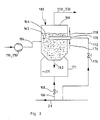
- Fig. 3 shows the detail III of Figures 1 and 2 as a variant.
- the plant according to FIG. 3 has a standing, circular fluidized bed reactor 160, in which the zeolitic catalyst material 162 forms a fluidized bed 164.
- the zeolitic catalyst material has a grain size of at most 1 mm and is brought into the fluidized state by a fluidizing gas, preferably a part of the residual gas fraction.
- the fluidizing gas is removed from the gas line 28 and fed through line 166 with the shut-off and regulating element 168 to the fluidizing gas lines 171, which introduce it into the lower, circular-conical area of the fluidized bed reactor 160.
- the fluidized bed 164 is supported by gas-fired heating tubes, of which a single heating tube 170 in fig. 3 is drawn, heated indirectly.
- the heating pipe is supplied with heating gas from the gas line 28 through the line 172 with the control and shut-off element 174 inserted.
- the combustion air is supplied to the heating pipe through line 176, whereas the exhaust gas flows out through line 178.
- the catalyst material is introduced into the fluidized bed reactor through line 180, the spent catalyst material is withdrawn through line 182 from the lower end of the fluidized bed reactor.
- the fluidized bed reactor 160 is constructed in exactly the same way as the pyrolysis reactor 10 in FIG. 1. It accordingly has an upper, circular-cylindrical region, which is followed by the circular-conical lower region, which tapers downward.
- the heating tube 170 is inserted horizontally into the fluidized bed 164 from the outside. A vertical introduction is just as possible.
- the gas from the cooling stage 46 or 246 is introduced into the fluidized bed 164 through the conduit 184 through the compressor 110 or 310 (see FIGS. 1 and 2).
- the fluidized bed is generated with the aid of fluidized gas, which is led through line 166 and the sufficiently open control and shut-off device 168 to the fluidized gas lines 171 and enters the lower region of the fluidized bed reactor 160.
- the gas supplied through line 184 comes into sufficient contact with the zeolitic catalyst material so that the reactions described above take place.
- the required temperature of the fluidized bed 164 of preferably 350 to 410 ° Celsius is generated by the heating tube 170.
- the catalytically treated gas mixture or the catalytically treated special gas fraction then flows through line 130 or 330 to further cooling stage 132 or 332 and is further processed there, as described above.
- the residence time of the gas in the fluidized bed is 0.4 to 1.5 seconds, preferably 0.5 to 1.1 seconds.
- the catalyst of FIG. 3 designed as a fluidized bed 164 has the advantage that the contacting of the gas with the catalyst material is more intensive.
- a good contact of the gas, which is fed through line 184 to the fluidized bed reactor 160, with the zeolites of the fluidized bed is also achieved when the gas is used as the fluidizing gas.
- line 166 is separated from gas line 28 and line 184 from fluidized bed reactor 160, and then line 184 connected to line 166.
- the gas supplied through line 184 additionally takes on the function of the fluidizing gas. This case is not shown in the drawings.
- the zeolitic catalyst was placed in a tube 4 mm wide. A free part of the tube arranged upstream of the catalyst served to bring the gas to the required reaction temperature of 370 ° Celsius.
- the subsequent pipe section is also heated to 370 ° Celsius and provided with a bed of the powdery, zeolitic catalyst over a length L.
- the residence time t is the ratio of the reaction zone to the volume velocity of the gas at the reaction temperature T.
- the dwell time has the dimension of seconds.
Landscapes
- Chemical & Material Sciences (AREA)
- Oil, Petroleum & Natural Gas (AREA)
- Engineering & Computer Science (AREA)
- Chemical Kinetics & Catalysis (AREA)
- General Chemical & Material Sciences (AREA)
- Life Sciences & Earth Sciences (AREA)
- Organic Chemistry (AREA)
- Wood Science & Technology (AREA)
- Production Of Liquid Hydrocarbon Mixture For Refining Petroleum (AREA)
- Catalysts (AREA)
- Organic Low-Molecular-Weight Compounds And Preparation Thereof (AREA)
- Processing Of Solid Wastes (AREA)
- Processing And Handling Of Plastics And Other Materials For Molding In General (AREA)
- Separation, Recovery Or Treatment Of Waste Materials Containing Plastics (AREA)
- Coke Industry (AREA)
Abstract
Bei der Aufarbeitung von CH-Verbindungen enthaltendem Abfallmaterial durch Pyrolyse entstehen eine Flüssigfraktion und eine Gasfraktion, wobei das Massenverhältnis dieser Fraktionen ungefähr gleich 1 ist. Da die Flüssigfraktion für eine Weiterverarbeitung geeigneter als die Gasfraktion ist, wird angestrebt, die Flüssigfraktion zu Lasten der Gasfraktion zu vergrößern.The processing of waste material containing CH compounds by pyrolysis produces a liquid fraction and a gas fraction, the mass ratio of these fractions being approximately equal to 1. Since the liquid fraction is more suitable for further processing than the gas fraction, the aim is to increase the liquid fraction at the expense of the gas fraction.
Um dies zu erreichen, wird das Pyrolysegas bis zum Übergang des Benzols und der höhersiedenden gasförmigen Pyrolysegas-Bestandteile in die flüssige Phase gekühlt, so daß eine benzolhaltige Flüssigfraktion entsteht. Aus der benzolhaltigen Flüssigfraktion wird ein Benzol- und Toluol enthaltendes Gasgemisch ausgetrieben und zusammen mit der Gasfraktion bei einer Temperatur von 300 bis 450° Celsius über einen zeolithischen Katalysator geleitet und dann durch Kühlung in eine bei Atmosphärendruck flüssigen Fraktion und eine Restgasfraktion getrennt.To achieve this, the pyrolysis gas is cooled until the benzene and the higher-boiling gaseous pyrolysis gas constituents pass into the liquid phase, so that a liquid fraction containing benzene is formed. A gas mixture containing benzene and toluene is driven off from the benzene-containing liquid fraction and passed together with the gas fraction at a temperature of 300 to 450 ° C. over a zeolitic catalyst and then separated by cooling into a fraction which is liquid at atmospheric pressure and a residual gas fraction.
Hierdurch wird der Anteil der Flüssigfraktion und somit die Wirtschaftlichkeit des Verfahrens wesentlich erhöht. As a result, the proportion of the liquid fraction and thus the economics of the process are significantly increased.
Description
Die Erfindung betrifft ein Verfahren zum Aufarbeiten von Kohlenwasserstoffverbindungen enthaltendem Abfallmaterial, insbesondere Kunststoff- oder Gummiabfälle enthaltendem Abfallmaterial, wobei das Abfallmaterial pyrolytisch zersetzt und das entstandene Pyrolysegas durch Kühlung in eine Flüssigfraktion und eine Gasfraktion überführt wird.The invention relates to a process for working up waste material containing hydrocarbon compounds, in particular waste material containing plastic or rubber waste, the waste material being pyrolytically decomposed and the pyrolysis gas formed being converted into a liquid fraction and a gas fraction by cooling.
Aus dem Allgemeinen Stand der Technik ist es bekannt, aus dem bei der Pyrolyse des Abfallmaterials gewonnenen Pyrolysegas durch eine durch Kühlung bewirkte teilweise Kondensation des Pyrolysegases eine Flüssigfraktion zu bilden, wobei das nichtkondensierte, verbleibende Pyrolysegas als Gasfraktion anfällt. Das Gewichtsverhältnis von Flüssigfraktion zu Gasfraktion hat einen Wert von ungefähr 1.It is known from the general prior art to form a liquid fraction from the pyrolysis gas obtained in the pyrolysis of the waste material by partial condensation of the pyrolysis gas caused by cooling, the uncondensed, remaining pyrolysis gas being obtained as a gas fraction. The weight ratio of liquid fraction to gas fraction has a value of approximately 1.
Die Gasfraktion, die hauptsächlich Wasserstoff, Methan, Ethan, Ethen, Propans Propen sowie in geringen Mengen - insgesamt ungefähr 5 Volumenprozent - höhere gesättigte und ungesättigte Kohlenwasserstoffe enthält, wird zu ungefähr 15 bis 30 Gew.% für die Durchführung des Pyrolyseverfahrens eingesetzt. Dies geschieht vorzugsweise durch die Verwendung der Gasfraktion als Heizgas und/oder im Falle einer Pyrolyse in einem Wirbelbett durch den Einsatz als Wirbelgas. Die noch übrig bleibende Gasfraktion ist trotz ihrer interessanten Bestandteile auf dem Markt kaum abzusetzen, auch sind Lagerung, Transport und Verarbeitung aufwendig und schwierig durchzuführen. Im Gegensatz hierzu ist die Verwertung oder Weiterverarbeitung der Flüssigfraktion, die wertvolle Bestandteile wie Benzol, Toluol und Xylol (BTX-Aromate) enthält, völlig unproblematisch.The gas fraction, which is mainly hydrogen, methane, ethane, ethene, propane and in small quantities - contains a total of approximately 5% by volume - higher saturated and unsaturated hydrocarbons, approximately 15 to 30% by weight is used to carry out the pyrolysis process. This is preferably done by using the gas fraction as heating gas and / or in the case of pyrolysis in a fluidized bed by using it as a fluidizing gas. The remaining gas fraction, despite its interesting components, can hardly be sold on the market, and storage, transport and processing are complex and difficult to carry out. In contrast, the recycling or further processing of the liquid fraction, which contains valuable components such as benzene, toluene and xylene (BTX aromatics), is completely unproblematic.
Der Erfindung liegt daher die Aufgabe zugrunde, bei einem Verfahren der eingangs genannten Art die Flüssigfraktion auf einfache Weise zu vergrößern.The invention is therefore based on the object of increasing the liquid fraction in a simple manner in a method of the type mentioned at the outset.
Zur Lösung dieser Aufgabe werden erfindungsgemäß zwei Wege vorgeschlagen. Der eine Lösungsweg besteht darin, daß das Pyrolysegas bis zum Übergang des in ihm enthaltenen gasförmigen Benzols sowie der höhersiedenden gasförmigen Pyrolysegas-Bestandteile in die flüssige Phase gekühlt und eine benzolhaltige Flüssigfraktion gebildet wird, daß aus der benzolhaltigen Flüssigfraktion ein Benzol und Toluol enthaltendes Gasgemisch gewonnen wird, daß das Gasgemisch zusammen mit der Gasfraktion bei einer Temperatur von 300 bis 450° Celsius mit einem zeolithischen Katalysator in Kontakt gebracht wird, und daß das katalytisch behandelte Gesgemisch durch Kühlung in eine bei Umgebungstemperatur flüssige Fraktion und eine Restgasfraktion getrennt wird.According to the invention, two ways are proposed to achieve this object. One solution is that the pyrolysis gas is cooled until the gaseous benzene contained therein and the higher-boiling gaseous pyrolysis gas components pass into the liquid phase, and a liquid fraction containing benzene is formed, so that a gas mixture containing benzene and toluene is obtained from the liquid fraction containing benzene that the gas mixture together with the gas fraction is brought into contact with a zeolitic catalyst at a temperature of 300 to 450 ° Celsius, and that the catalytically treated mixture is separated by cooling into a fraction which is liquid at ambient temperature and a residual gas fraction.
Es wird also das Pyrolysegas soweit gekühlt, daß das in ihm enthaltene gasförmige Benzol einschließlich der Be standteile, die einen gegenüber Benzol höheren Siedepunkt haben, in die flüssige Phase übertreten und eine benzolhaltige Flüssigfraktion entsteht. Da das Benzol bei Umgebungsdruck einen Siedepunkt von 80° Celsius besitzt und die Kühlung ungefähr bei Umgebungsdruck durchgeführt wird, muß das Pyrolysegas ungefähr auf 75 bis 80° Celsius abgekühlt werden, um die benzolhaltige Flüssigfraktion zu erhalten. Diese benzolhaltige Flüssigfraktion wird nun auf eine Temperatur oberhalb des Siedepunkts des Toluols erhitzt und ein Gasgemisch ausgetrieben, das zusammen mit der nach der Gewinnung der benzolhaltigen Flüssigfraktion übriggebliebenen Gasfraktion über einen zeolithischen Katalysator bei erhöhter Temperatur geleitet wird. Hierbei reagieren die in der Gasfraktion vorhandenen Olefine mit den niedriger siedenden und in gasförmiger Form vorliegenden Anteilen der Flüssigfraktion, insbesondere Benzol und Toluol, zu kondensierbaren Produkten. Aus Benzol und Ethen entsteht hierbei Ethylbenzol. Überraschenderweise entsteht keineswegs soviel Isopropylbenzol, wie dem ursprünglichen Propengehalt der Restgasfraktion entsprochen hätte. Es muß vielmehr davon ausgegangen werden, daß Propen mit Propen selbst zu Benzol reagiert und alkyliert wird. Insgesamt gesehen entsteht ein katalytisch behandeltes Gasgemisch, das eine große Zahl von alkylierten Aromaten enthält. Durch Kühlung werden diese Aromaten in eine bei Umgebungsdruck flüssige Fraktion und eine Restgasfraktion getrennt. Hierbei zeigt es sich, daß die in der Gasfraktion enthaltenen Olefine zu mehr als 80 bis 90 Gew.% verschwunden sind und in flüssige und somit leicht transportierbare und marktgängige Kohlenwasserstoffe umgewandelt worden sind.So the pyrolysis gas is cooled to such an extent that the gaseous benzene it contains, including Be Components that have a higher boiling point than benzene, pass into the liquid phase and a liquid fraction containing benzene is formed. Since the benzene has a boiling point of 80 ° Celsius at ambient pressure and the cooling is carried out approximately at ambient pressure, the pyrolysis gas must be cooled to approximately 75 to 80 ° Celsius in order to obtain the benzene-containing liquid fraction. This benzene-containing liquid fraction is then heated to a temperature above the boiling point of the toluene and a gas mixture is expelled which, together with the gas fraction remaining after the benzene-containing liquid fraction has been obtained, is passed over a zeolitic catalyst at elevated temperature. The olefins present in the gas fraction react with the lower-boiling and gaseous fractions of the liquid fraction, in particular benzene and toluene, to form condensable products. Here, ethylbenzene is formed from benzene and ethene. Surprisingly, there is by no means as much isopropylbenzene as the original propene content of the residual gas fraction. Rather, it must be assumed that propene reacts with propene itself to form benzene and is alkylated. All in all, a catalytically treated gas mixture is created that contains a large number of alkylated aromatics. By cooling, these aromatics are separated into a fraction that is liquid at ambient pressure and a residual gas fraction. This shows that more than 80 to 90% by weight of the olefins contained in the gas fraction have disappeared and have been converted into liquid and thus easily transportable and marketable hydrocarbons.
Die verbleibende Restgasfraktion, in der nur noch sehr wenig Olefine vorhanden sind (ungefähr 3 Gew.%), enthält im wesentlichen Wasserstoff, Methan, Ethan, Propan sowie Spuren ungesättigter und gesättigter höherer Kohlenwasserstoffe. Obwohl diese Restgasfraktion jetzt nur noch 30 bis 35 Gew.% des Einsatzgutes beträgt, ist sie noch vollständig ausreichend, um das Pyrolyseverfahren autark zu betreiben. Die Restgasfraktion enthält noch genügend Anteile an gesättigten C1- bis C3-Kohlenwasserstoffverbindungen und ist daher für den Einsatz z.B. als Heizgas und Wirbelgas für die Durchführung des Pyrolyseverfahrens bestens geeignet und ausreichend.The remaining residual gas fraction, in which very little olefins are still present (approximately 3% by weight), contains essentially hydrogen, methane, ethane, propane and traces of unsaturated and saturated higher hydrocarbons. Although this residual gas fraction is now only 30 to 35% by weight of the feed, it is still completely sufficient to operate the pyrolysis process independently. The residual gas fraction still contains sufficient proportions of saturated C1 to C3 hydrocarbon compounds and is therefore very suitable and sufficient for use, for example, as heating gas and fluidizing gas for carrying out the pyrolysis process.
Der zweite Weg zur Lösung der Aufgabe besteht erfindungsgemäß darin, daß die Kühlung des Pyrolysegases auf eine solche Temperatur durchgeführt wird, bei der eine besondere Gasfraktion entsteht, deren Anteile an C2- und C3-Olefinen sowie C6- und C7-Aromaten ein Molverhältnis von ungefähr 1 aufweisen, daß die besondere Gasfraktion mit einem zeolithischen Katalysator bei einer Temperatur von 300 bis 450° Celsius in Kontakt gebracht wird, und daß die katalytisch behandelte besondere Gasfraktion durch Kühlung in eine bei Atmosphärendruck flüssige Fraktion und eine Restgasfraktion getrennt wird.The second way to achieve the object according to the invention is that the cooling of the pyrolysis gas is carried out to a temperature at which a special gas fraction is formed, the proportions of C2 and C3 olefins and C6 and C7 aromatics in a molar ratio of approximately 1 have that the special gas fraction is brought into contact with a zeolitic catalyst at a temperature of 300 to 450 ° Celsius, and that the catalytically treated special gas fraction is separated by cooling into a fraction liquid at atmospheric pressure and a residual gas fraction.
Im Unterschied zum ersten Lösungsweg wird aus dem Pyrolysegas zunächst keine Flüssigfraktion gewonnen und daraus ein Benzol und Toluol enthaltendes Gasgemisch erzeugt. Das Pyrolysegas wird vielmehr lediglich auf eine solche Temperatur abgekühlt, bei der eine besondere Gasfraktion entsteht, die Anteile an C2- und C3-Olefinen sowie C6- und C7-Aromaten aufweist, wobei das Molverhältnis der C2- und C3-Olefine zu den C6- und C7-Aromaten ungefähr 0,8 bis 1,2, vorzugsweise ungefähr 1 beträgt. Zur Erzeugung dieser besonderen Gasfraktion muß das Pyrolysegas auf eine Temperatur von ungefähr 80 bis 100° Celsius abgekühlt werden. Die besondere Gasfraktion wird dann genauso wie beim ersten Lösungsweg und mit dem gleichen Endergebnis weiterbehandelt.In contrast to the first approach, no liquid fraction is initially obtained from the pyrolysis gas and a gas mixture containing benzene and toluene is generated therefrom. Rather, the pyrolysis gas is only cooled to a temperature at which a special gas fraction is formed, which contains fractions of C2 and C3 olefins and C6 and C7 aromatics, the molar ratio of the C2 and C3 olefins to the C6 and C7 aromatics is about 0.8 to 1.2, preferably about 1. To generate this special gas fraction, the pyrolysis gas must be cooled to a temperature of approximately 80 to 100 ° Celsius. The special gas fraction is then treated just like the first solution and with the same end result.
Für die Gewinnung der besonderen Gasfraktion ist es zweckmäßig, daß die Kühlung der besonderen Gasfraktion auf ein Temperatur oberhalb des Siedepunkts des Benzols durchgeführt wird, vorzugsweise auf eine Temperatur die höchstens um 10 bis 20° Celsius oberhalb des Siedepunkts liegt. Da das Verfahren ungefähr bei Umgebungsdruck durchgeführt wird, sind die Angaben des Siedepunktes auf Umgebungsdruck bezogen. Wird die Kühlung bei einem Druck durchgeführt, der vom Umgebungsdruck abweicht, so ist die Kühltemperatur dem Druck entsprechend zu ändern.To obtain the special gas fraction, it is expedient that the cooling of the special gas fraction is carried out to a temperature above the boiling point of the benzene, preferably to a temperature which is at most 10 to 20 ° C. above the boiling point. Since the process is carried out at approximately ambient pressure, the information about the boiling point is based on ambient pressure. If the cooling is carried out at a pressure that deviates from the ambient pressure, the cooling temperature must be changed according to the pressure.
Gemäß einer vorteilhaften Weiterbildung der Erfindung, die besonders für die Aufarbeitung von Abfallmaterial bis zu einer Jahresleistung von 10 000 Tonnen geeignet ist, wird der Katalysator als Festbettkatalysator ausgebildet und die Kontaktzeit des Gasgemisches bzw. der besonderen Gasfraktion mit dem Katalysator auf 0,3 bis 2 Sekunden, vorzugsweise 0,7 bis 1,5 Sekunden, festgelegt.According to an advantageous development of the invention, which is particularly suitable for the processing of waste material up to an annual output of 10,000 tons, the catalyst is designed as a fixed bed catalyst and the contact time of the gas mixture or the special gas fraction with the catalyst is 0.3 to 2 Seconds, preferably 0.7 to 1.5 seconds.
Bei höheren Durchsätzen -über 10 000 Tonnen pro Jahr-empfiehlt es sich, daß der Katalysator in feinkörniger Form verwendet und zur Bildung eines Wirbelbettes eingesetzt wird, und daß die Kontaktzeit des Gasgemisches bzw. der besonderen Gasfraktion mit dem Wirbelbett 0,4 bis 1,5 Sek., vorzugsweise 0,5 bis 1,1 Sek. beträgt.At higher throughputs - over 10,000 tons per year - it is recommended that the catalyst is used in fine-grained form and used to form a fluidized bed, and that the contact time of the gas mixture or the special gas fraction with the fluidized bed is 0.4 to 1, 5 seconds, preferably 0.5 to 1.1 seconds.
Damit eine möglichst große flüssige Fraktion entsteht, wird gemäß einer bevorzugten Ausgestaltung der Erfindung das Gasgemisch bzw. die besondere Gasfraktion bei einer Temperatur von 350 bis 410° Celsius mit dem Katalysator in Kontakt gebracht. Aus dem gleichen Grunde ist es zweckmäßig, daß als Katalysator der handelsübliche Katalysator ZSM5 eingesetzt wird.In order that the largest possible liquid fraction is formed, the gas mixture or the special gas fraction is brought into contact with the catalyst at a temperature of 350 to 410 ° Celsius according to a preferred embodiment of the invention. For the same reason, it is expedient that the commercially available catalyst ZSM5 is used as the catalyst.
Weitere Vorteile und Merkmale des erfindungsgemäßen Verfahrens gehen aus der folgenden Beschreibung von Ausführungsbeispielen von Pyrolyseanlagen hervor, die für die Durchführung des Verfahrens geeignet und die in den Zeichnungen schematisch dargestellt sind.Further advantages and features of the method according to the invention emerge from the following description of exemplary embodiments of pyrolysis plants which are suitable for carrying out the method and which are shown schematically in the drawings.
Hierbei zeigt:
- Fig. 1 das Schaltschema einer Pyrolyseanlage für die Durchführung des Verfahrens gemäß dem ersten Lösungsweg,
- Fig. 2 eine Pyrolyseanlage für die Durchführung des Verfahrens gemäß dem zweiten Lösungsweg und
- Fig. 3 die Einzelheit III der Figuren 1 und 2 als Ausführungsvariante.
- 1 shows the circuit diagram of a pyrolysis plant for carrying out the method according to the first approach,
- Fig. 2 shows a pyrolysis plant for performing the method according to the second approach and
- Fig. 3 shows the detail III of Figures 1 and 2 as a variant.
In den einzelnen Figuren wiederkehrende gleiche Bauteile sind nur insoweit mit Bezugszeichen versehen, als dies für das Verständnis erforderlich ist.Identical components recurring in the individual figures are provided with reference numerals only to the extent that this is necessary for understanding.
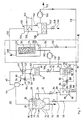
Die Anlage gemäß Fig. 1 weist einen stehenden Pyrolysereaktor 10 auf, dessen oberer Bereich 12 kreiszylindrisch ausgebildet ist. Der sich nach unten anschließende untere Bereich 14 verjüngt sich kreiskegelförmig nach unten und ist an seinem Ende mit einer Abfuhrleitung 16 versehen. Das sich während des Betriebs im Pyrolysereaktor ausbildende Wirbelbett 18 weist eine vertikale Höhe auf, die ungefähr 80 bis 90% der lichten Höhe des Pyrolysereaktors beträgt, so daß oberhalb des Wirbelbettes ein Gasraum 20 frei bleibt. Für das Einbringen des Abfallmaterials in den Pyrolysereaktor ist eine Zufuhrleitung 22 vorgesehen, die in das Wirbelbett 18 mündet. Im unteren Bereich 14 sind an den Pyrolysereaktor Wirbelgasleitungen 24 angeschlossen, die unter Zwischenschaltung eines Regel- und Absperrorgans 26 mit der Gasleitung 28 verbunden sind. In das Wirbelbett 18 tauchen mehrere Heizrohre horizontal oder vertikal ein, von denen in den Zeichnungen der Übersicht wegen lediglich ein einziges Heizrohr 30 dargestellt ist. Die gasbefeuerten Heizrohre 30 dienen zur indirekten Erhitzung des Wirbelbettes. Zur Heizgasversorgung sind die Heizrohre 30 durch eine Leitung 32 mit eingefügtem Regel- und Absperrorgan 34 an die Gasleitung 28 angeschlossen, in der die brennbare Restgasfraktion geführt wird, die in der Anlage erzeugt wird und als Heizgas und Wirbelgas dient. Die für die Verbrennung erforderliche Verbrennungsluft wird jedem Heizrohr durch eine Leitung 36 zugeführt, die Abgase werden jeweils durch eine Abgasleitung 38 in die Umgebung 40 abgeleitet.1 has a standing
Der Gasraum 20 des Pyrolysereaktors ist durch eine Leitung 42 mit einer Kühlstufe 46 verbunden, wobei in die Leitung 42 ein Zyklonabscheider 44 eingefügt ist. Die Leitung 42 ist an das obere Ende eines zylindrischen, stehenden Kühlers 48 der Kühlstufe angeschlossen, das untere Ende des Kühlers mündet in einen Abscheidebehälter 50. Im Kühler selbst ist eine Kühlschlange 52 angeordnet, die durch die Leitung 54 mit einem Kühlmedium, vorzugsweise Kühlwasser oder Kühlsole, versorgt wird. Die Abfuhr des Kühlmediums geschieht durch die Leitung 56. In die Leitung 54 ist ein Dreiwegeventil 58 eingefügt, dessen dritter Anschluß durch eine Leitung 60 mit der Leitung 56 verbunden ist. Zur Betätigung des Dreiwegeventils 58 ist im Kühler 48 unterhalb der Kühlschlange 52 ein Temperaturfühler 62 vorgesehen, der durch eine gestrichelt gezeichnete Steuerleitung 64 mit dem Dreiwegeventil 58 verbunden ist. Erforderlichenfalls ist in die Steuerleitung noch ein nicht dargestellter Kraftverstärker eingefügt.The
Der untere Bereich des Abscheidebehälters 50 dient als Flüssigkeitsraum 66, der darüber verbleibende freie Raum 68 dient als Gasraum.The lower region of the separating
Der Flüssigkeitsraum 66 ist unten durch eine Leitung 70 mit eingefügtem Absperr- und Regelorgan 72 mit dem oberen Bereich 74 eines stehenden, kreiszylindrischen und geschlossenen Verdampfungsbehälters 76 verbunden. Im unteren Bereich 78 des Verdampfungsbehälters ist eine Heizschlange 80 angeordnet und durch eine Vorlaufleitung 82 und eine Rücklaufleitung 84 mit einem Heizkessel 86 verbunden. Hierbei ist in die Vorlaufleitung 82 ein Dreiwegemischventil 88 eingefügt und mit einer Mischleitung 90 mit der Rücklaufleitung 84 verbunden. Zur Betätigung des Dreiwegemischventils 88 ist im unteren Bereich 78 des Verdampfungsbehälters 76 ein Temperaturfühler 92 angeordnet, der durch eine gestrichelt gezeichnete Steuerleitung 94 auf das Dreiwegemischventil 88 einwirkt. Am tiefsten Punkt des Verdampfungsbehälters 76 ist noch eine Leitung 96 vorgesehen, in die ein der Zeichnung nicht dargestelltes Absperrorgan eingefügt ist.The
Der Heizkessel 86 ist mit einem Gasbrenner 98 versehen, der durch eine Leitung 100 mit eingefügtem Regel- und Absperrorgan 102 mit der Gasleitung 28 verbunden ist. Das Abgas des Heizkessels 86 wird durch die Abgasleitung 104 an die Umgebung abgeführt.The
Der freie Raum 68 des Abscheidebehälters 50 sowie der obere Bereich 74 des Verdampfungsbehälters 76 sind jeweils durch eine Leitung 106 bzw. 108 mit dem Eingang eines Gasförderers oder Verdichters 110 verbunden. Der Ausgang des Verdichters 110 ist durch die Leitung 112 mit dem unteren Ende eines stehenden, zylindrischen Behälters 114 verbunden, in dem der Katalysator in Form von stückigen Zeolithen 116 vorhanden ist, es handelt sich demnach um einen Festbettkatalysator. Der Behälter 114 ist zur Beheizung des Katalysators unter Bildung eines allseitigen Zwischenraumes 118 von einem Mantel 120 umgeben. Unterhalb des Behälters 114 ist im Zwischenraum 118 ein Gasbrenner 122 angeordnet, der durch eine Leitung 124 mit eingefügtem Regel- und Absperrorgan 126 mit der Gasleitung 28 verbunden ist. Für die Abfuhr der Verbrennungsabgase ist an den oberen Bereich des Zwischenraums 118 eine Abgasleitung 128 angeschlossen, die in die Umgebung 40 mündet. Die Stückgröße der Zeolithe beträgt ungefähr 3 bis 20mm.The
Das obere Ende des Behälters 114 ist durch eine Leitung 130 mit einer weiteren Kühlstufe 132 verbunden. Hierbei mündet die Leitung 130 in das obere Ende eines stehendes, kreiszylindrischen Kühlers 134, dessen unteres Ende in einen weiteren Abscheidebehälter 136 mündet. Im Kühler 134 ist eine Kühlschlange 138 angeordnet, deren Kühlwasser- oder Kühlsoleversorgung durch die Leitungen 140 erfolgt. Der stehende, kreiszylindrische weitere Abscheidebehälter 136 weist einen unteren Bereich 142 auf, der für die Aufnahme von Flüssigkeit vorgesehen ist, wogegen der darüber verbleibende obere Bereich 144 für die Aufnahme von Gasen bestimmt ist. An der tiefsten Stelle des unteren Bereiches 142 ist eine Leitung 146 angeschlossen, die mit einem Absperrorgan 148 versehen ist.The upper end of the
An den oberen Bereich 144 des weiteren Abscheidebehälters 136 ist unter Zwischenschaltung eines Gasförderers oder Verdichters 150 die Gasleitung 28 angeschlossen. Mit der Gasleitung 28 ist stromab des Verdichters 150 noch die Leitung 152 verbunden, durch die überschüssiges Gas entnommen und Verbrauchern, z.B. zur Raumheizung, zugeführt wird. Die Verbraucher sind in Fig. 1 nicht dargestellt.The
Falls es erforderlich sein sollte, empfiehlt es sich, zwischen den Verdichter 150 und den oberen Bereich 144 des weiteren Abscheidebehälters 136 noch mindestens eine weitere Kühlstufe und/oder einen Gaswäscher einzuschalten. Dies wird man dann tun, wenn das Gas am Ausgang der weiteren Kühlstufe 132 noch nicht auf Umgebungstemperatur abgekühlt ist und/oder noch Verunreinigungen enthalten sollte. Die vorgenannte Kühlstufe und der Gaswäscher ist in Fig. 1 nicht eingezeichnet.If it should be necessary, it is advisable to switch on at least one further cooling stage and / or a gas scrubber between the
Während des Betriebs strömt aus der Gasleitung 28 Gas, das hier als Wirbelgas dient, durch die Wirbelgasleitungen 24 in den Pyrolysereaktor 10. Hierdurch wird das dort vorhandene feinkörnige Wirbelmedium, vorzugsweise Sand mit einer Korngröße kleiner als 0,5mm, verwirbelt und es entsteht das Wirbelbett 18. Der Massenstrom des Gases, der für die Erzeugung des Wirbelbettes erforderlich ist, wird durch das Regel- und Absperrorgan 26 eingestellt. Gleichzeitig wird dem Heizrohr 30 Gas, das hier als Heizgas dient, durch die Leitung 32 sowie Verbrennungsluft durch die Leitung 36 zugeführt und das Heizrohr durch die Gasverbrennung soweit erhitzt, daß es in der Lage ist, das Wirbelbett 18 auf eine Temperatur von 400 bis 1000° Celsius, vorzugsweise 600 bis 900° Celsius aufzuheizen. Das aus dem Heizrohr austretende Abgas wird durch die Abgasleitung 38 abgeführt, vorzugsweise zu einem nichtdargestellten Kamin. Die Heizleistung des Heizrohres wird durch das Regel- und Absperrorgan 34 eingestellt, mit dem die Gaszufuhr reguliert werden kann.During operation, gas, which serves here as a fluidizing gas, flows from the
Das Abfallmaterial mit einer Stückgröße von zweckmäßig ungefähr maximal 10cm wird durch die Zufuhrleitung 22 in den unteren Bereich des Wirbelbettes eingebracht und dort in reduzierender Atmosphäre, das heißt in Abwesenheit von Sauerstoff, thermisch zersetzt. Die hierbei entstehenden brennbaren Pyrolysegase sammeln sich im Gasraum 20 des Pyrolysereaktors 10, wogegen der Pyrolyserückstand durch die Abfuhrleitung 16 aus dem Pyrolysereaktor abgeführt wird.The waste material with a piece size of appropriately approximately a maximum of 10 cm is introduced through the feed line 22 into the lower region of the fluidized bed and there thermally decomposed in a reducing atmosphere, i.e. in the absence of oxygen. The combustible pyrolysis gases formed in this way collect in the
Aus dem Gasraum 20 strömt das Pyrolysegas durch die Leitung 42 zur Kühlstufe 46, wobei im Zyklonabscheider 44 vom Pyrolysegas mitgeführte feste Teilchen abgeschieden werden. Das Pyrolysegas tritt in den stehenden Kühler 48 oben ein und wird durch die Kühlschlange 48 gekühlt. Hierzu wird der Kühlschlange 52 Kühlwasser durch die Leitung 54 zugeführt, das nach der Wärmeaufnahme durch die Leitung 56 abgeführt wird. In der Leitung 54 ist ein Dreiwegemischventil 58 eingebaut, das über die Leitung 60 mit der Leitung 56 verbunden ist. Durch das Dreiwegemischventil wird die Temperatur und der Zustrom des Kühlwassers zu der Kühlschlange so eingestellt, daß das im Pyrolysegas enthaltene gasförmige Benzol sowie die höhersiedenden gasförmigen Bestandteile kondensieren und als Flüssigfraktion abgeschieden werden. Der Siedepunkt des Benzols liegt bei Umgebungsdruck bei 80° Celsius, das Pyrolysegas muß demnach im Kühler 48 auf eine Temperatur von ungefähr 75 bis 79° Celsius abgekühlt werden. Um diese Abkühlung sicherzustellen, ist im Kühler 48 unterhalb der Kühlschlange 52 ein Temperaturfühler 62 angeordnet, der durch die Steuerleitung 64 auf das Dreiwegemischventil 58 einwirkt. Hierzu wird das Dreiwegemischventil derart verstellt, daß sich in der Kühlschlange 52 eine Kühlwasserströmung einstellt, welche die gewünschte Kühlung erzielt.The pyrolysis gas flows from the
Im Kühler 48 kondensiert nicht nur das Benzol, sondern es kondensieren auch jene Bestandteile des Pyrolysega ses, deren Siedepunkte höher liegen als der des Benzols. Insbesondere kondensiert das im Pyrolysegas enthaltene Toluol, das ein Siedepunkt von ungefähr 111° Celsius aufweist. Die Kondensation in der Kühlstufe 46 findet bei Umgebungsdruck statt.Not only does the benzene condense in the cooler 48, but also those components of the Pyrolysega condense ses whose boiling points are higher than that of benzene. In particular, the toluene contained in the pyrolysis gas condenses, which has a boiling point of approximately 111 ° Celsius. The condensation in cooling
Die kondensierten Bestandteile, welche die benzolhaltige Flüssigfraktion bilden, sammeln sich im Flüssigkeitsraum 66 des Abscheidebehälters 50 und werden durch die Leitung 70 mit eingefügten Regel- und Absperrorgan 72 in den stehenden Verdampfungsbehälter 76 geleitet, wo sie sich im unteren Bereich 78 sammeln. Hierbei ist das Regel- und Absperrorgan 72 so eingestellt, daß sich im Flüssigkeitsraum 66 immer ein Teil der benzolhaltigen Flüssigfraktion enthalten ist und somit ein Gasübertritt vom oberen Bereich 74 des Verdampfungsbehälters zum freien Raum 68 des Abscheidebehälters vermieden ist. Im unteren Bereich 78 des Verdampfungsbehälters ist eine Heizschlange 80 vorgesehen, die durch die Vorlaufleitung 82 und die Rücklaufleitung 84 mit dem Wasser-Heizkessel 86 verbunden ist. Dieser Heizkessel ist durch einen schematisch angedeuteten Gasbrenner 98 beheizt, der durch die Leitung 100 mit eingefügtem Absperr- und Regelorgan 102 von der Gasleitung 28 mit Heizgas versorgt wird. Das Abgas wird durch die Abgasleitung 104 an die Umgebung abgegeben.The condensed constituents, which form the benzene-containing liquid fraction, collect in the
In der Vorlaufleitung 82 ist das Dreiwegemischventil 88 angeordnet, das durch die Steuerleitung 74 mit dem Temperaturfühler 92 verbunden ist. Dieser Temperaturfühler 92 ist im unteren Bereich 78 des Verdampfungsbehälters 76 angeordnet und regelt den Massenstrom und die Temperatur des Heizwassers in der Heizschlange 80. Die Regelung ist hierbei so eingestellt, daß die im unteren Bereicht 78 gesammelte benzolhaltige Flüssigfraktion so weit erhitzt wird, daß das Benzol und das Toluol in gasförmiger form ausgetrieben werden und ein Benzol un Toluol enthaltenes Gasgemisch entsteht, das sich im oberen Bereich 74 sammelt. Die Erhitzung der benzolhaltigen Flüssigfraktion erfolgt bei Umgebungsdruck auf eine Temperatur über 111°C, vorzugsweise auf 120 bis 140°C. Das Gasgemisch wird durch die Leitung 108 dem Verdichter 110 zugeführt. Gleichzeitig strömt durch die Leitung 106 die im Kühler 48 anfallende und nach der Gewinnung der benzolhaltigen Flüssigfraktion übrig gebliebene Gasfraktion zum Verdichter 110 und vermischt sich mit dem Benzol und Toluol enthaltenden Gasgemisch, so daß ein Gesamtgasstrom entsteht. Dieser Gesamtgasstrom wird durch die Leitung 112 in den Behälter 118 unten eingeführt und durchströmt den zeolithischen Katalysator nach oben. Der Behälter 114 und somit der Katalysator 116 ist durch den schematisch angedeuteten Gasbrenner 122 beheizt, der durch die Leitung 124 und das Regel- und Absperrorgan 126 von der Gasleitung 28 mit Heizgas versorgt wird. Die Beheizung des Katalysators erfolgt hierbei auf eine Temperatur von vorzugsweise 350 bis 410° Celsius durch die im Zwischenraum 118 zur Abgasleitung 128 strömenden Rauchgase. Der Querschnitt des Behälters und somit des Katalysatorfestbettes ist so gewählt, daß das durchströmende Gas 0,3 bis 2 Sekunden, vorzugsweise 0,7 bis 1,5 Sekunden, mit dem Katalysator in Kontakt bleibt. Während des Durchströmens des Katalysators reagieren die in der Gasfraktion vorhandenen gasförmigen Olefine mit dem gasförmigen Benzol und Toluol zu gasförmigen Produkten, die bei einer Abkühlung als flüssig Fraktion anfallen. Hierduch wird der Anteil der Gasfraktion zu Gunsten der Flüssigfraktion verringert.The three-
Für die Gewinnung der flüssigen Fraktion wird der aus dem Behälter 114 austretende, katalytisch behandelte Gesamtgasstrom durch die Leitung 130 der weiteren Kühlstufe 132 zugeführt und in den stehenden Kühler 134 oben eingeleitet. Die dort eingebaute Kühlschlange 138, die durch die Leitungen 144 mit Kühlwasser oder Kühlsole versorgt wird, kühlt den katalytisch behandelten Gesamtgasstrom auf eine Temperatur von 20 bis 60° Celsius ab. Das hierbei kondensierende Pyrolyseöl bildet die flüssige Fraktion und strömt zusammen mit dem übrigbleibenden Gas, das die Restgasfraktion darstellt, nach unten zum stehenden, weiteren Abscheidebehälter 136. Hier sammelt sich die Flüssigfraktion im unteren Bereich 142, die Restgasfraktion ist im oberen Bereich 144 des weiteren Abscheidebehälters 136 vorhanden. Die Flüssigfraktion wird durch die Leitung 146 aus dem weiteren Abscheidebehälter abgezogen und weiterverarbeitet, die brennbare Restgasfraktion wird dem Verdichter 150 zugeführt und in die Gasleitung 28 gefördert. Die Restgasfraktion wird als Heizgas den Gasbrennern und als Wirbelgas dem Pyrolysereaktor zugeführt. Das in der Anlage nicht benötigte restliche Gas wird durch die Leitung 152 weiteren Verbrauchern zugeführt, die in Fig. 1 nicht dargestellt sind.In order to obtain the liquid fraction, the catalytically treated which emerges from the
In Fig. 2 ist eine Ausführungsvariante der Pyrolyeanlage gemäß Fig. 1 dargestellt. Der Unterschied gegenüber Fig. 1 besteht darin, daß die Kühlstufe anders ausgebildet ist und der Heizkessel 86 sowie der damit verbundene Verdampfungsbehälter 76 fehlen. Im übrigen sind Bauteile der Fig. 1, die in identischer Form in Fig. 2 erscheinen, mit Bezugszeichen versehen, die gegenüber den Bezugszeichen der Fig. 1 um den Betrag 200 erweitert sind.FIG. 2 shows an embodiment variant of the pyrolyzer according to FIG. 1. The difference compared to Fig. 1 is that the cooling stage is designed differently and the
Die Anlage gemäß Fig. 2 weist eine Kühlstufe 246 auf, die einen stehenden Kühler 248 aufweist. Im Kühler ist eine Kühlschlange 252 vorgesehen, die genauso wie die Kühlschlange 52 der Fig. 1 mit Kühlwasser versorgbar ist. An das untere Ende des Kühlers 248 ist ein Abscheidebehälter 250 angeschlossen, dessen unterer Raum als Flüssigkeitsraum 266 dient, wogegen der darüber verbleibende freie Raum 268 für die Aufnahme von Gas vorgesehen ist. Vom freien Raum 268 führt eine Leitung 306 zum Behälter 314, der den zeolithischen Katalysator enthält, wobei in die Leitung 306 ein Verdichter 310 oder ein Gasförderer eingeschaltet ist.The system according to FIG. 2 has a cooling stage 246, which has a standing cooler 248. A cooling
Das in der Leitung 254 vorgesehene Dreiwegemischventil 258 ist zur Steuerung durch die gestrichelt gezeichnete Steuerleitung 154 mit einem Meß- und Regelgerät 156 verbunden. Dieses Meß- und Regelgerät erfaßt das Molverhältnis der C2- und C3-Olefine zu den C6- und C7-Aromaten der im freien Raum 268 anstehenden besonderen Gasfraktion. Hierzu wird durch die Leitung 155 dem reien Raum 268 Gas mit Hilfe einer nicht dargestellten Gaspumpe, vorzugsweise eines Verdichters, entnommen, durch das Meß- und Regelgerät geleitet und dann durch die Leitung 158 wieder dem freien Raum 268, oder besser der Leitung 306 stromauf des Verdichters 310 zugeführt, so daß ein dauernder Gasstrom durch das Meß- und Regelgerät 156 aufrechterhalten wird. Das Meß- und Regelgerät ist nun so ausgebildet, daß das Dreiwegemischventil 258 und somit die Kühlleistung des Kühlers 248 derart eingestellt wird, daß die im freien Raum anfallende besondere Gasfraktion ein Molverhältnis von ungefähr 0,8 bis 1,2, vorzugsweise 1, zwischen den C2- und C3-Olefinen und den C6- und C7-Aromaten aufweist.The three-
Während des Betriebs der Anlage wird, genau wie beim Ausführungsbeispiel gemäß Fig. 1, dem Pyrolysereaktor 210 das Abfallmaterial zugeführt und im Wirbelbett 218 thermisch zersetzt. Das entstandene Pyrolysegas wird aus dem Gasraum 220 durch den Zyklonabscheider 244 zum oberen ende des stehenden Kühlers 248 geleitet, der bei Umgebungsdruck arbeitet. Hier wird das Pyrolysegas abgekühlt, wobei ein Teil des Pyrolyegases kondensiert und als Pyrolyseöl im Flüssigkeitsraum 266 des Abscheidebehälters 250 aufgefangen wird. von hier wird dieses Pyrolyseöl zur Weiterverarbeitung entnommen.1, the waste material is fed to the
Gleichzeitig wird ein geringer Teil, z.B. 0,5%, des gekühlten Pyrolysegases durch das Meß- und Regelgerät 156 geführt und das Molverhältnis zwischen den C2- und den C3-Olefinen einerseits und den C6- und C7-Aromaten andererseits gemessen. Da dieses Molverhältnis ungefähr den betrag 1 haben soll, wird vom Meß- und Regelgerät 156 das Dreiwegemischventil 258 und damit die Kühlleistung der Kühlschlange 252 derart eingeregelt, daß das gekühlte Pyrolysegas im freien Raum 268 dieses gewünschte Molverhältnis aufweist. Dieses Pyrolysegas wird als besondere Gasfraktion bezeichnet. Um die besondere Gasfraktion zu erhalten, ist eine Kühlung des Pyrolysegases auf eine Temperatur oberhalb des Siedepunktes des Toluols erforderlich. Die besondere Gasfraktion wird dann durch die Leitung 306 mit eingefügtem Verdichter 310 dem Behälter 314 zugeführt, in dem der zeolithische Katalysator 316 als Festbett enthalten ist. Die Wirkungsweise des zeolithischen Katalysators 316 sowie der weitere Lauf des Gases ist hier genauso, wie es im Zusammenhang mit Fig. 1 beschrieben wurde, so daß sich hier weiteres erübrigt.At the same time, a small part, e.g. 0.5% of the cooled pyrolysis gas passed through the measuring and
Bei dieser Ausführungsvariante werden wie auch bei der Anlage gemäß Fig. 1 die Olefine in gesättigte C bis C-5 Kohlenwasserstoffe umgewandelt, die in der nachgeschalteten weiteren Kühlstufe 332 als flüssig Fraktion anfallen und von dort zur Weiterverarbeitung entnommen werden. Durch die erfindungsgemäßen Verfahrensschritte wird die Restgasfraktion zu Gunsten der flüssigen Fraktion um 20 bis 30% vermindert und somit die Wirtschaftlichkeit der Anlage erhöht.In this embodiment variant, as in the system according to FIG. 1, the olefins are converted into saturated C to C-5 hydrocarbons, which are obtained in the downstream
Fig. 3 zeigt die Einzelheit III der Figuren 1 und 2 als Ausführungsvariante. Anstatt den zeolithischen Katalysator 116 bzw. 316 als Festbettkatalysator auszubilden, weist die Anlage gemäß Fig. 3 einen stehenden, kreisförmigen Wirbelbettreaktor 160 auf, in dem das zeolithische Katalysatormaterial 162 ein Wirbelbett 164 bildet. Hierzu weist das zeolithische Katalysatormaterial eine Körnung von höchstens 1 mm auf und ist durch ein Wirbelgas, vorzugsweise einen Teil der Restgasfraktion, in den Wirbelzustand versetzt. Das Wirbelgas wird der Gasleitung 28 entnommen und durch die Leitung 166 mit eingefügtem Absperr-und Regelorgan 168 den Wirbelgasleitungen 171 zugeführt, die es in den unteren, kreiskegelförmigen Bereich des Wirbelbettreaktors 160 einleiten. Das Wirbelbett 164 wird durch gasbefeuerte Heizrohre, von denen ein einziges Heizrohr 170 in fig. 3 gezeichnet ist, indirekt erhitzt. Hierzu wird das Heizrohr durch die Leitung 172 mit eingefügtem Regel- und Absperrorgan 174 von der Gasleitung 28 mit Heizgas versorgt. Die Verbrennungsluft wird durch die Leitung 176 dem Heizrohr zugeführt, wogegen das Abgas durch die Leitung 178 abströmt. Das Katalysatormaterial wird durch die Leitung 180 oben in den Wirbelbettreaktor eingebracht, das verbrauchte Katalysatormaterial wird durch die Leitung 182 vom unteren Ende des Wirbelbettreaktors abgezogen. Der Wirbelbettreaktor 160 ist genauso aufgebaut, wie der Pyrolysereaktor 10 der Fig. 1. Er besitzt demnach einen oberen, kreiszylindrischen Bereich, an den sich der sich nach unten verjüngende kreiskegelförmige untere Bereich anschließt. Das Heizrohr 170 ist horizontal vom Außenraum in das Wirbelbett 164 eingeführt. Eine vertikale Einführung ist ebensogut möglich.Fig. 3 shows the detail III of Figures 1 and 2 as a variant. Instead of designing the
Während des Betriebs wird das Gas aus der Kühlstufe 46 bzw. 246 durch den Verdichter 110 bzw. 310 (vergl. Fig. 1 und 2) durch die Leitung 184 in das Wirbelbett 164 eingeführt. Das Wirbelbett wird mit Hilfe von Wirbelgas erzeugt, das durch die Leitung 166 und das ausreichend geöffnete Regel- und Absperrorgan 168 zu den Wirbelgasleitungen 171 geführt wird und in den unteren Bereich des Wirbelbettreaktors 160 eintritt. Im Wirbelbett 164 kommt das durch die Leitung 184 zugeführte Gas mit dem zeolithischen Katalysatormaterial in ausreichenden Kontakt, so daß die weiter oben beschriebenen Reaktionen stattfinden. Die hierzu erforderliche Temperatur des Wirbelbettes 164 von vorzugsweise 350 bis 410° Celsius wird durch das Heizrohr 170 erzeugt. Das katalytisch behandelte Gasgemisch bzw. die katalytisch behandelte besondere Gasfraktion strömt dann durch die Leitung 130 bzw. 330 zur weiteren kühlstufe 132 bzw. 332 und wird dort, wie weiter oben beschrieben, weiterbehandelt. Die Verweilzeit des Gases im Wirbelbett beträgt 0,4 bis 1,5 Sekunden, vorzugsweise 0,5 bis 1,1 Sekunden.During operation, the gas from the cooling
Gegenüber dem zeolithischen Katalysator 116 bzw. 316, der als Festbettkatalysator in einem Behälter 114 bzw. 314 angeordnet ist, weist der als Wirbelbett 164 ausgebildete Katalysator der Fig. 3 den Vorteil auf, daß die Kontaktierung des Gases mit dem Katalysatormaterial intensiver ist.Compared to the
Ein guter Kontakt des Gases, das durch die Leitung 184 dem Wirbelbettreaktor 160 zugeführt wird, mit den Zeolithen des Wirbelbettes wird auch dann erreicht, wenn das Gas als Wirbelgas benutzt wird. Hierzu wird die Leitung 166 von der Gasleitung 28 und die Leitung 184 vom Wirbelbettreaktor 160 getrennt und dann die Leitung 184 an die Leitung 166 angeschlossen. Jetzt übernimmt das durch die Leitung 184 zugeführte Gas zusätzlich die Funktion des Wirbelgases. Dieser Fall ist in den Zeichnungen nicht dargestellt.A good contact of the gas, which is fed through
Bezüglich der als Katalysator eingesetzten Zeolithe wird auf folgenden Aufsatz verwiesen: Lothar Puppe "Zeolithe - Eigenschaften und technische Anwendungen", Chemie in unserer Zeit, 20. Jahrgang 1986, Nr. 4, VCH Verlagsgesellschaft mbH, D-6940 Weinheim, Seiten 117 bis 127. Dort ist auch der bevorzugt eingesetzte zeolithische Katalysator ZSM5 genannt, der folgende Zusammensetzung aufweist: Na0,3H3,8[(ALO₂)4,1(SiO₂)91,9].With regard to the zeolites used as catalysts, reference is made to the following article: Lothar Puppe "Zeolites - Properties and Technical Applications", Chemistry in Our Time, 20th Year 1986, No. 4, VCH Verlagsgesellschaft mbH, D-6940 Weinheim, pages 117 to 127 The preferred zeolitic catalyst ZSM5 is mentioned there, which has the following composition: Na 0.3 H 3.8 [(ALO₂) 4.1 (SiO₂) 91.9 ].
In Laboratoriumsversuchen wurde die Wirksamkeit des erfindungsgemäßen Verfahrens überprüft. Hierzu war der zeolithische Katalysator in ein Rohr von 4mm lichter Weite eingebracht. Ein stromaufwärts des Katalysators angeordneter freier Teil des Rohres diente dazu, das Gas auf die erforderliche Reaktionstemperatur von 370° Celsius zu bringen. Der sich anschließende Rohrteil ist ebenfalls auf 370° Celsius aufgeheizt und auf einer Länge L mit einer Schüttung des pulverförmigen, zeolithischen Katalysators versehen.The effectiveness of the method according to the invention was checked in laboratory tests. For this purpose, the zeolitic catalyst was placed in a tube 4 mm wide. A free part of the tube arranged upstream of the catalyst served to bring the gas to the required reaction temperature of 370 ° Celsius. The subsequent pipe section is also heated to 370 ° Celsius and provided with a bed of the powdery, zeolitic catalyst over a length L.
Als Verweilzeit t ist das Verhältnis der Reaktionszone zur Volumengeschwindigkeit des Gases bei der Reaktionstemperatur T angegeben. Die Verweilzeit hat die Dimension Sekunden.The residence time t is the ratio of the reaction zone to the volume velocity of the gas at the reaction temperature T. The dwell time has the dimension of seconds.
Bei den weiter unten angegebenen Versuchen wurden äquimolare Mengen an Benzol und Olefinen eingesetzt. Die Ausbeute in Prozent wurde nach der folgenden Beziehung errechnet:
Alle anderen ( in geringen Mengen entstandenen) Produkte sind vernachlässigt. Das bedeutet die tatsächliche Ausbeute an alkylierten Produkten ist höher als der jeweils angegebene Wert. Die einzelnen Versuche führten zu folgenden Ergebnissen.
Claims (7)
Na0,3H3,8 [(AlO₂)4,1(SiO₂)91,9].7. The method according to at least one of claims 1 to 6, characterized in that the catalyst ZSM5 is used, which has the following composition:
Na 0.3 H 3.8 [(AlO₂) 4.1 (SiO₂) 91.9 ].
Priority Applications (1)
| Application Number | Priority Date | Filing Date | Title |
|---|---|---|---|
| AT88120665T ATE74617T1 (en) | 1987-12-23 | 1988-12-10 | PROCESSES FOR PROCESSING WASTE MATERIAL. |
Applications Claiming Priority (2)
| Application Number | Priority Date | Filing Date | Title |
|---|---|---|---|
| DE19873743752 DE3743752A1 (en) | 1987-12-23 | 1987-12-23 | METHOD FOR PROCESSING WASTE MATERIAL |
| DE3743752 | 1987-12-23 |
Publications (3)
| Publication Number | Publication Date |
|---|---|
| EP0321807A2 true EP0321807A2 (en) | 1989-06-28 |
| EP0321807A3 EP0321807A3 (en) | 1990-03-07 |
| EP0321807B1 EP0321807B1 (en) | 1992-04-08 |
Family
ID=6343391
Family Applications (1)
| Application Number | Title | Priority Date | Filing Date |
|---|---|---|---|
| EP88120665A Expired - Lifetime EP0321807B1 (en) | 1987-12-23 | 1988-12-10 | Process for recycling waste materials |
Country Status (6)
| Country | Link |
|---|---|
| US (1) | US4871426A (en) |
| EP (1) | EP0321807B1 (en) |
| JP (1) | JPH01210493A (en) |
| CN (1) | CN1016439B (en) |
| AT (1) | ATE74617T1 (en) |
| DE (2) | DE3743752A1 (en) |
Cited By (3)
| Publication number | Priority date | Publication date | Assignee | Title |
|---|---|---|---|---|
| DE19517096A1 (en) * | 1995-05-10 | 1996-11-14 | Daniel Engelhardt | Pyrolysis process for plastics operating at relatively low temps. |
| US10239049B2 (en) | 2011-02-17 | 2019-03-26 | AMG Chemistry and Catalysis Consulting, LLC | Alloyed zeolite catalyst component, method for making and catalytic application thereof |
| US10987661B2 (en) | 2011-02-17 | 2021-04-27 | AMG Chemistry and Catalysis Consulting, LLC | Alloyed zeolite catalyst component, method for making and catalytic application thereof |
Families Citing this family (24)
| Publication number | Priority date | Publication date | Assignee | Title |
|---|---|---|---|---|
| JPH0717914B2 (en) * | 1989-08-28 | 1995-03-01 | モービル オイル コーポレーション | Method for producing low boiling hydrocarbon oil |
| JPH0386791A (en) * | 1989-08-31 | 1991-04-11 | Mobil Oil Corp | Method for producing low-boiling hydrocarbon oil |
| US5369215A (en) * | 1992-04-06 | 1994-11-29 | S-P Reclamation, Inc. | Depolymerization method for resource recovery from polymeric wastes |
| US5504267A (en) * | 1992-04-06 | 1996-04-02 | S-P Reclamation, Inc. | Resource recovery by catalytic conversion of polymers |
| US5360553A (en) * | 1992-09-17 | 1994-11-01 | Baskis Paul T | Process for reforming materials into useful products and apparatus |
| DE4311034A1 (en) * | 1993-04-03 | 1994-10-06 | Veba Oel Ag | Process for the extraction of chemical raw materials and fuel components from old or waste plastic |
| DE4418562A1 (en) * | 1993-06-29 | 1995-01-12 | Leybold Durferrit Gmbh | Method and device for treating material consisting essentially of plastic or rubber |
| CN1060203C (en) * | 1995-01-17 | 2001-01-03 | 王选玉 | Method for producing carbon black, liquefied gas and petroleum oil products by using waste rubber |
| CN1055419C (en) * | 1995-07-04 | 2000-08-16 | 张庆祥 | Aromatization catalyst of waste plastics and preparation process |
| JP3402877B2 (en) * | 1995-10-09 | 2003-05-06 | 三菱重工業株式会社 | Method and apparatus for producing carbon black from waste tires |
| JP2002248453A (en) * | 2000-06-16 | 2002-09-03 | Akira Shibata | Unnecessary material recycling system |
| US8877992B2 (en) * | 2003-03-28 | 2014-11-04 | Ab-Cwt Llc | Methods and apparatus for converting waste materials into fuels and other useful products |
| US7179379B2 (en) * | 2003-03-28 | 2007-02-20 | Ab-Cwt, Llc | Apparatus for separating particulates from a suspension, and uses thereof |
| US7692050B2 (en) * | 2003-03-28 | 2010-04-06 | Ab-Cwt, Llc | Apparatus and process for separation of organic materials from attached insoluble solids, and conversion into useful products |
| DE102004003667A1 (en) * | 2004-01-24 | 2005-08-11 | Nill Tech Gmbh | Recovering fractionated hydrocarbons from plastics and/or oil residues comprises compression, melting, evaporation, heating, cracking and condensing |
| AR057141A1 (en) * | 2005-09-28 | 2007-11-21 | Cwt Llc Ab | DEPOLIMERIZATION PROCESSING TO CONVERT ORGANIC AND NON-ORGANIC WASTE PRODUCTS IN USEFUL PRODUCTS |
| US7531703B2 (en) | 2005-10-06 | 2009-05-12 | Ecoplastifuel, Inc. | Method of recycling a recyclable plastic |
| EP2240269B1 (en) | 2007-12-27 | 2019-03-27 | Elcon Recycling Center (2003) Ltd. | Safely processing a fluid via monitoring and decreasing explosiveness of vapor-gas species formed therefrom or contained therein |
| FR2945294B1 (en) * | 2009-05-07 | 2012-04-20 | Olivier Lepez | METHOD AND INSTALLATION FOR ENERGETIC DENSIFICATION OF A PRODUCT IN THE FORM OF DIVIDED SOLIDS FOR OBTAINING ENERGY-EFFICIENT PYROLYTIC OILS |
| US9447332B2 (en) | 2013-02-12 | 2016-09-20 | Saudi Basic Industries Corporation | Conversion of plastics to olefin and aromatic products using temperature control |
| US9428695B2 (en) | 2013-02-12 | 2016-08-30 | Saudi Basic Industries Corporation | Conversion of plastics to olefin and aromatic products with product recycle |
| US8895790B2 (en) | 2013-02-12 | 2014-11-25 | Saudi Basic Industries Corporation | Conversion of plastics to olefin and aromatic products |
| JP2022528272A (en) * | 2019-03-29 | 2022-06-09 | バイオビーティーエックス・ベー・フェー | Method for Producing Low Molecular Weight Aromatic Compounds such as Benzene, Toluene and Xylene (BTX) from Plastics |
| JPWO2021166854A1 (en) * | 2020-02-21 | 2021-08-26 |
Family Cites Families (8)
| Publication number | Priority date | Publication date | Assignee | Title |
|---|---|---|---|---|
| DE2658371C2 (en) * | 1976-12-23 | 1983-03-03 | Carl Robert Eckelmann AG, 2000 Hamburg | Process for pyrolyzing old tires |
| DE2917293C2 (en) * | 1979-04-27 | 1987-05-27 | Herko Pyrolyse Gmbh & Co Recycling Kg, 6832 Hockenheim | Process for the production of oils from waste materials |
| DE2941393B1 (en) * | 1979-10-12 | 1981-05-14 | Rütgerswerke AG, 6000 Frankfurt | Process for separating and separating soot and OEl from a cracked gas product |
| US4308411A (en) * | 1980-08-28 | 1981-12-29 | Occidental Research Corporation | Process for converting oxygenated hydrocarbons into hydrocarbons |
| JPS5936624B2 (en) * | 1982-04-05 | 1984-09-05 | 東京都 | Alkylbenzene recovery method from polyolefin plastic waste and benzene |
| US4584421A (en) * | 1983-03-25 | 1986-04-22 | Agency Of Industrial Science And Technology | Method for thermal decomposition of plastic scraps and apparatus for disposal of plastic scraps |
| DE3545954A1 (en) * | 1985-12-23 | 1987-07-02 | Bbc Brown Boveri & Cie | METHOD FOR THE PYROLYTIC REPRODUCTION OF STARTING MATERIAL |
| JPS63178195A (en) * | 1987-01-20 | 1988-07-22 | 工業技術院長 | Production of low boiling point hydrocarbon oil from polyolefinic plastic |
-
1987
- 1987-12-23 DE DE19873743752 patent/DE3743752A1/en active Granted
-
1988
- 1988-12-10 EP EP88120665A patent/EP0321807B1/en not_active Expired - Lifetime
- 1988-12-10 AT AT88120665T patent/ATE74617T1/en not_active IP Right Cessation
- 1988-12-10 DE DE8888120665T patent/DE3869930D1/en not_active Expired - Lifetime
- 1988-12-22 JP JP63324760A patent/JPH01210493A/en active Pending
- 1988-12-22 CN CN88108966A patent/CN1016439B/en not_active Expired
- 1988-12-23 US US07/289,608 patent/US4871426A/en not_active Expired - Fee Related
Cited By (4)
| Publication number | Priority date | Publication date | Assignee | Title |
|---|---|---|---|---|
| DE19517096A1 (en) * | 1995-05-10 | 1996-11-14 | Daniel Engelhardt | Pyrolysis process for plastics operating at relatively low temps. |
| US10239049B2 (en) | 2011-02-17 | 2019-03-26 | AMG Chemistry and Catalysis Consulting, LLC | Alloyed zeolite catalyst component, method for making and catalytic application thereof |
| US10421062B2 (en) | 2011-02-17 | 2019-09-24 | AMG Chemistry and Catalysis Consulting, LLC | Alloyed zeolite catalyst component, method for making and catalytic application thereof |
| US10987661B2 (en) | 2011-02-17 | 2021-04-27 | AMG Chemistry and Catalysis Consulting, LLC | Alloyed zeolite catalyst component, method for making and catalytic application thereof |
Also Published As
| Publication number | Publication date |
|---|---|
| US4871426A (en) | 1989-10-03 |
| DE3743752C2 (en) | 1990-02-08 |
| ATE74617T1 (en) | 1992-04-15 |
| CN1033830A (en) | 1989-07-12 |
| JPH01210493A (en) | 1989-08-24 |
| DE3869930D1 (en) | 1992-05-14 |
| CN1016439B (en) | 1992-04-29 |
| EP0321807A3 (en) | 1990-03-07 |
| DE3743752A1 (en) | 1989-07-13 |
| EP0321807B1 (en) | 1992-04-08 |
Similar Documents
| Publication | Publication Date | Title |
|---|---|---|
| EP0321807B1 (en) | Process for recycling waste materials | |
| EP0226895B1 (en) | Process for the pyrolytic upgrading of starting material | |
| DE69913994T2 (en) | FLASH PYROLYSIS IN A CYCLONE | |
| DE2910614C2 (en) | ||
| DE19681320C2 (en) | Process for supercritical catalytic gasification of wet biomass | |
| WO2010003968A2 (en) | Method and device for producing low-tar synthesis gas from biomass | |
| DE69909929T2 (en) | Process for the production of methanol | |
| EP0126407A2 (en) | Process for recovering a useful gas from waste by pyrolysis, and apparatus for carrying out the process | |
| DE2855174A1 (en) | METHOD AND DEVICE FOR RETURNING THE CARRIER GAS IN GAS CHROMATOGRAPHIC SYSTEMS | |
| DE2019475C3 (en) | Indirectly heated vertical tube furnace for the production of low molecular weight olefins by thermal cleavage of more saturated hydrocarbons | |
| DE102004038220B4 (en) | Thermal biomass oiling | |
| DE2910287A1 (en) | METHOD FOR HYDROGENATING SOLID CARBON MATERIAL | |
| DE1645864B2 (en) | PLANT FOR GENERATING OLEFINS BY THERMAL CLEARAGE OF HYDROCARBONS IN THE FLOW METHOD AND METHOD FOR GENERATING OLEFINS USING THIS PLANT | |
| EP0418847B1 (en) | Plant for processing a filtration slurry containing essentialy diatomaceous earth and process for operating the plant | |
| DE2656598A1 (en) | METHOD AND DEVICE FOR CONVERTING SOLID WASTE INTO PIPELINEGAS | |
| AT403018B (en) | METHOD FOR CATALYTICALLY CONVERTING ORGANIC WASTE IN THE LOW TEMPERATURE RANGE | |
| DE102018117674A1 (en) | Process and device for producing activated carbon | |
| DE2805244A1 (en) | METHOD AND DEVICE FOR COOLING DUSTY OR FINE-GRAINED SOLIDS | |
| EP1506806B1 (en) | Process and plant for regeneration of gas washing liquids | |
| DE69926430T2 (en) | Process for the conversion of hydrocarbons by treatment in a distillation unit connected to a reaction zone and application for the hydrogenation of benzene | |
| EP0209665B1 (en) | Coal hydrogenation process by liquid phase and fixed-bed catalyst hydrogenation | |
| DE1301320B (en) | Process for the catalytic synthesis of melamine from urea | |
| DE937723C (en) | Method and apparatus for converting hydrocarbons into lighter products | |
| DE60023468T2 (en) | METHOD AND DEVICE FOR CLEANING A PRODUCT GAS FROM A GASIFICATION REACTOR | |
| EP0308669A1 (en) | Process for utilising a halogenated hydrocarbon-containing starting material |
Legal Events
| Date | Code | Title | Description |
|---|---|---|---|
| PUAI | Public reference made under article 153(3) epc to a published international application that has entered the european phase |
Free format text: ORIGINAL CODE: 0009012 |
|
| AK | Designated contracting states |
Kind code of ref document: A2 Designated state(s): AT BE CH DE GB IT LI NL SE |
|
| PUAL | Search report despatched |
Free format text: ORIGINAL CODE: 0009013 |
|
| AK | Designated contracting states |
Kind code of ref document: A3 Designated state(s): AT BE CH DE GB IT LI NL SE |
|
| 17P | Request for examination filed |
Effective date: 19900817 |
|
| 17Q | First examination report despatched |
Effective date: 19910313 |
|
| GRAA | (expected) grant |
Free format text: ORIGINAL CODE: 0009210 |
|
| AK | Designated contracting states |
Kind code of ref document: B1 Designated state(s): AT BE CH DE GB IT LI NL SE |
|
| REF | Corresponds to: |
Ref document number: 74617 Country of ref document: AT Date of ref document: 19920415 Kind code of ref document: T |
|
| REF | Corresponds to: |
Ref document number: 3869930 Country of ref document: DE Date of ref document: 19920514 |
|
| ITF | It: translation for a ep patent filed | ||
| GBT | Gb: translation of ep patent filed (gb section 77(6)(a)/1977) | ||
| PG25 | Lapsed in a contracting state [announced via postgrant information from national office to epo] |
Ref country code: GB Effective date: 19921210 Ref country code: AT Effective date: 19921210 |
|
| PG25 | Lapsed in a contracting state [announced via postgrant information from national office to epo] |
Ref country code: SE Effective date: 19921211 |
|
| PG25 | Lapsed in a contracting state [announced via postgrant information from national office to epo] |
Ref country code: LI Effective date: 19921231 Ref country code: CH Effective date: 19921231 Ref country code: BE Effective date: 19921231 |
|
| PLBE | No opposition filed within time limit |
Free format text: ORIGINAL CODE: 0009261 |
|
| STAA | Information on the status of an ep patent application or granted ep patent |
Free format text: STATUS: NO OPPOSITION FILED WITHIN TIME LIMIT |
|
| 26N | No opposition filed | ||
| BERE | Be: lapsed |
Owner name: ASEA BROWN BOVERI A.G. Effective date: 19921231 |
|
| PG25 | Lapsed in a contracting state [announced via postgrant information from national office to epo] |
Ref country code: NL Effective date: 19930701 |
|
| GBPC | Gb: european patent ceased through non-payment of renewal fee |
Effective date: 19921210 |
|
| NLV4 | Nl: lapsed or anulled due to non-payment of the annual fee | ||
| REG | Reference to a national code |
Ref country code: CH Ref legal event code: PL |
|
| PG25 | Lapsed in a contracting state [announced via postgrant information from national office to epo] |
Ref country code: DE Effective date: 19930901 |
|
| EUG | Se: european patent has lapsed |
Ref document number: 88120665.0 Effective date: 19930709 |
|
| PG25 | Lapsed in a contracting state [announced via postgrant information from national office to epo] |
Ref country code: IT Free format text: LAPSE BECAUSE OF NON-PAYMENT OF DUE FEES;WARNING: LAPSES OF ITALIAN PATENTS WITH EFFECTIVE DATE BEFORE 2007 MAY HAVE OCCURRED AT ANY TIME BEFORE 2007. THE CORRECT EFFECTIVE DATE MAY BE DIFFERENT FROM THE ONE RECORDED. Effective date: 20051210 |