EP0321443A2 - Process and installation for continuously melting scrap - Google Patents
Process and installation for continuously melting scrap Download PDFInfo
- Publication number
- EP0321443A2 EP0321443A2 EP88890316A EP88890316A EP0321443A2 EP 0321443 A2 EP0321443 A2 EP 0321443A2 EP 88890316 A EP88890316 A EP 88890316A EP 88890316 A EP88890316 A EP 88890316A EP 0321443 A2 EP0321443 A2 EP 0321443A2
- Authority
- EP
- European Patent Office
- Prior art keywords
- converter
- channel
- tapping device
- tapping
- radial
- Prior art date
- Legal status (The legal status is an assumption and is not a legal conclusion. Google has not performed a legal analysis and makes no representation as to the accuracy of the status listed.)
- Granted
Links
- 238000000034 method Methods 0.000 title claims abstract description 23
- 238000002844 melting Methods 0.000 title claims abstract description 7
- 230000008018 melting Effects 0.000 title claims abstract description 7
- 238000009434 installation Methods 0.000 title 1
- 238000010079 rubber tapping Methods 0.000 claims abstract description 40
- 239000002893 slag Substances 0.000 claims abstract description 14
- 239000000155 melt Substances 0.000 claims abstract description 10
- 238000002485 combustion reaction Methods 0.000 claims abstract description 5
- 229910000805 Pig iron Inorganic materials 0.000 claims abstract description 4
- 238000005070 sampling Methods 0.000 claims description 4
- 239000001301 oxygen Substances 0.000 description 6
- 229910052760 oxygen Inorganic materials 0.000 description 6
- VNWKTOKETHGBQD-UHFFFAOYSA-N methane Chemical compound C VNWKTOKETHGBQD-UHFFFAOYSA-N 0.000 description 5
- 238000010309 melting process Methods 0.000 description 4
- QVGXLLKOCUKJST-UHFFFAOYSA-N atomic oxygen Chemical compound [O] QVGXLLKOCUKJST-UHFFFAOYSA-N 0.000 description 3
- 239000000446 fuel Substances 0.000 description 3
- 230000000717 retained effect Effects 0.000 description 3
- XEEYBQQBJWHFJM-UHFFFAOYSA-N Iron Chemical compound [Fe] XEEYBQQBJWHFJM-UHFFFAOYSA-N 0.000 description 2
- 239000003345 natural gas Substances 0.000 description 2
- 230000003647 oxidation Effects 0.000 description 2
- 238000007254 oxidation reaction Methods 0.000 description 2
- 230000001105 regulatory effect Effects 0.000 description 2
- 238000007664 blowing Methods 0.000 description 1
- 239000003245 coal Substances 0.000 description 1
- 238000010924 continuous production Methods 0.000 description 1
- 230000004927 fusion Effects 0.000 description 1
- 239000007789 gas Substances 0.000 description 1
- 238000010438 heat treatment Methods 0.000 description 1
- 230000001771 impaired effect Effects 0.000 description 1
- 229910052742 iron Inorganic materials 0.000 description 1
- 239000002184 metal Substances 0.000 description 1
- 229910052751 metal Inorganic materials 0.000 description 1
- 239000007769 metal material Substances 0.000 description 1
- CSJDCSCTVDEHRN-UHFFFAOYSA-N methane;molecular oxygen Chemical compound C.O=O CSJDCSCTVDEHRN-UHFFFAOYSA-N 0.000 description 1
- 239000000203 mixture Substances 0.000 description 1
- 239000012768 molten material Substances 0.000 description 1
- 238000000926 separation method Methods 0.000 description 1
- 238000007711 solidification Methods 0.000 description 1
- 230000008023 solidification Effects 0.000 description 1
- 239000000725 suspension Substances 0.000 description 1
Images
Classifications
-
- C—CHEMISTRY; METALLURGY
- C21—METALLURGY OF IRON
- C21C—PROCESSING OF PIG-IRON, e.g. REFINING, MANUFACTURE OF WROUGHT-IRON OR STEEL; TREATMENT IN MOLTEN STATE OF FERROUS ALLOYS
- C21C5/00—Manufacture of carbon-steel, e.g. plain mild steel, medium carbon steel or cast steel or stainless steel
- C21C5/56—Manufacture of steel by other methods
- C21C5/567—Manufacture of steel by other methods operating in a continuous way
-
- C—CHEMISTRY; METALLURGY
- C21—METALLURGY OF IRON
- C21C—PROCESSING OF PIG-IRON, e.g. REFINING, MANUFACTURE OF WROUGHT-IRON OR STEEL; TREATMENT IN MOLTEN STATE OF FERROUS ALLOYS
- C21C5/00—Manufacture of carbon-steel, e.g. plain mild steel, medium carbon steel or cast steel or stainless steel
- C21C5/28—Manufacture of steel in the converter
-
- Y—GENERAL TAGGING OF NEW TECHNOLOGICAL DEVELOPMENTS; GENERAL TAGGING OF CROSS-SECTIONAL TECHNOLOGIES SPANNING OVER SEVERAL SECTIONS OF THE IPC; TECHNICAL SUBJECTS COVERED BY FORMER USPC CROSS-REFERENCE ART COLLECTIONS [XRACs] AND DIGESTS
- Y02—TECHNOLOGIES OR APPLICATIONS FOR MITIGATION OR ADAPTATION AGAINST CLIMATE CHANGE
- Y02P—CLIMATE CHANGE MITIGATION TECHNOLOGIES IN THE PRODUCTION OR PROCESSING OF GOODS
- Y02P10/00—Technologies related to metal processing
- Y02P10/20—Recycling
Definitions
- the invention relates to a method for the continuous melting of scrap and / or pig iron in a converter and to an apparatus for carrying out this method.
- the known allothermic furnaces for preheating scrap and / or melts are usually heated by floor nozzles which blow carbon-oxygen mixtures into the floor sump or by blowing fuels with oxygen through a lance introduced from above.
- the so-called KVA process is operated with metallic insert as well as coal and aggregates, whereby it is known with this KVA process to apply the necessary heat of fusion by natural gas-oxygen burners.
- the melting crucibles previously proposed as part of the KVA process have a bottom tapping with which continuous work is not readily possible. With these known methods it was already possible to move mobile pans under the tap opening, the slag being discharged together with the molten bath and the slag being removed from the subsequent pan.
- the invention now aims to provide a method of the type mentioned at the outset with which it is possible to conduct the melting process continuously and with a constant bath quality.
- the method according to the invention consists essentially in that the converter is heated near the bottom with substoichiometric burners, the flames of which are directed essentially radially into the interior of the converter, that secondary air or O2 for complete combustion is at a distance above the burner level is supplied that the melt is discharged into a mobile pan, possibly together with slag, via a tapping device connected to the side of the converter, and that the converter is pivoted into a position for changing the pan, in which the melt level lies below the tap opening.
- the natural gas-oxygen ratio can be regulated in such a way that, in particular when using natural gas-oxygen burners the desired flame temperatures and the desired degree of oxidation is achieved.
- the use of substoichiometric burners leads to an improvement in iron output and a reduction in oxidation loss. Because secondary air or oxygen is now supplied for complete combustion at a distance above the burner level, the chemically bound heat is largely fully utilized and the continuously added batch is preheated to a high degree, so that the Procedure is accelerated.
- the unburned fuel portion is post-burned as completely as possible with the help of controllable air quantities and in this way the scrap column is preheated.
- the melt is now discharged into a mobile pan together with slag via a tapping device connected to the side of the converter, the possibility is created of retaining a sufficient amount of slag in the converter when the converter is pivoted, so that the continuous melting process continues the pivoting back of the converter after the exchange of the pan moved underneath is in no way impaired.
- any slag that may be discharged with the molten bath can be separated off by separating it in the collecting pan underneath, the tapping device projecting from the side allowing a sufficient volume of the slag to be retained in the converter even at small pivoting angles.
- the metallic material that continues to melt can be retained in the converter, so that the continuity of the process is maintained, for which it is only sufficient to pivot the converter for a ladle change into a position in which the melt level lies below the tap opening.
- the device according to the invention for carrying out this method has a converter and is essentially characterized in that a plurality of essentially radially directed burner nozzles is arranged on the converter in a plane near the converter base, and air nozzles are arranged in a further plane above and that an oriel-shaped tapping device is connected to the converter via a radial tap opening.
- the bay-shaped tapping device which is connected to the converter via a radial tap opening and which verifies the kinematics of the pivoting process improves that a pan change without dripping is possible even with small pivoting angles of the converter.
- the bay-shaped tapping device has an essentially radial channel which is aligned with the radial tap opening of the converter and that a tapping channel which is essentially parallel to the axis of the converter is connected to the essentially radial channel, such a channel angled design of the channels in the tapping device offers the possibility of finding sufficiency with small pivoting angles for changing the ladle and creates the possibility of arranging additional devices which ensure the continuity of the process.
- Burners are advantageously directed into each of the two channels, namely both into the essentially radial channel aligned with the radial tap opening of the converter and also into the further channel angled with respect to this first channel, thereby ensuring a homogeneous temperature distribution.
- the design according to the invention is advantageously made such that the channel of the tapping device connected to the radial tap opening has a larger clear cross-section than the channel of the tapping device parallel to the axis of the converter, which creates the possibility of connecting the burners to a space free of melt to connect the essentially radial first channel.
- the burner nozzles can be of one immediate exposure to the molten pool are kept free and the training is in a particularly simple manner such that two burners with crossing or intersecting flame axes and a closable sampling opening are connected to the channel of the tapping device connected to the radial tap opening.
- the connection for sampling which also opens into this channel, enables the process to be continuously monitored and allows the burner of the converter to be regulated in the desired manner.
- a particularly rapid change of the movable pans succeeds when the design is made such that the outlet end of the tapping channel of the bay-shaped tapping device carries a lid for the pan that can be moved under the tapping channel, which lid can be pivoted together with the converter and lifted off the pan.
- the fact that the lid of the subsequent pan is connected to the converter or the bay-shaped tapping device means that the pan can be changed particularly quickly, as a result of which the process is interrupted only very briefly.
- the burners of the converter are advantageously operated with a lack of oxygen, which gives a ⁇ of 0.8 to 0.9.
- the unburned parts of the natural gas, especially CO and CH4 rise with the exhaust gases and are completely burned in the area of the secondary air supply level.
- the use of a converter allows simple pivoting to change the pan and the device according to the invention can be put into practice directly by converting existing converters, for example by converting LD converters.
- the pivotable suspension of the converter allows a significantly improved accessibility below the converter, with the cumbersome manipulations as they occur in connection with on the ground tapping openings arranged by converters are required in the case of the bay-shaped tapping device with integrated burners.
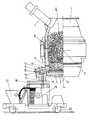
- a pivotable converter 1 is shown, the pivot axis of which is designated by 2.
- Radially directed natural gas burners 4 are connected to the converter near the converter base 3 via a ring line, the flames 5 of which are directed essentially radially into the interior of the converter.
- the converter 1 can be continuously loaded with scrap 6, for which a feed chute 7 is provided.
- Another ring line 8 for the supply of secondary air is located above the burner level formed by the burners 4. Since the burners 4 are operated sub-stoichiometrically with a ⁇ of 0.8 to 0.9, the fuels introduced are completely combusted in the secondary air level.
- An oriel-shaped tapping device 9 which has an essentially radial channel 10, is connected to the converter base 3.
- This radial channel 10 of the bay-shaped tapping device 9 is aligned with a radial tap opening 11 of the converter 1 and merges into a channel 13 which is essentially vertical to the axis 12 of the converter 1.
- the essentially radial channel 10 has a larger clear cross section than the tapping channel 13 parallel to the axis 12, so that the radial channel 10 does not have to be completely filled for the melt pool to drain off.
- the burner 15 serves for heating the radial channel 10, whereas the burner 16 prevents the vertical channel 13 from becoming blocked by solidification of metal.
- a sampling opening 17 is also connected to the radial channel 10, via which the melting process can be controlled.
- a lid 18 is connected to the bay-shaped tapping device 9, which together with the converter 1 and the bay-shaped tapping opening 9 can be pivoted up about the pivot axis 2 if the pan 19 underneath it is to be replaced.
- the pan 19 itself can be moved on rollers 20 and a separate slag collecting vessel 21 is fixed to the undercarriage of the pan 19 for slag separation.
Landscapes
- Engineering & Computer Science (AREA)
- Chemical & Material Sciences (AREA)
- Manufacturing & Machinery (AREA)
- Materials Engineering (AREA)
- Metallurgy (AREA)
- Organic Chemistry (AREA)
- Carbon Steel Or Casting Steel Manufacturing (AREA)
- Vertical, Hearth, Or Arc Furnaces (AREA)
- Waste-Gas Treatment And Other Accessory Devices For Furnaces (AREA)
- Furnace Details (AREA)
Abstract
Bei einem Verfahren zum kontinuierlichen Schmelzen von Schrott (6) und/oder Roheisen in einem Konverter (1) wird der Konverter (1) nahe dem Boden (3) mit unterstöchiometrischen Brennern (4), deren Flammen (5) im wesentlichen radial in das Innere des Konverters (1) gerichtet sind, beheizt. Hiebei wird in Abstand oberhalb der Brennerebene Sekundärluft oder O₂ zur vollständigen Verbrennung zugeführt. Die Schmelzel (14) wird über eine seitlich an den Konverter (1) angeschlossene Absticheinrichtung (9) gegebenenfalls gemeinsam mit Schlacke in eine fahrbare Pfanne (19) ausgetragen. Zum Pfannenwechsel (19) wird der Konverter (1) in eine Lage verschwenkt wird, in welcher der Schmelzespiegel unterhalb der Abstichöffnung (11) liegt. 
Description
Die Erfindung bezieht sich auf ein Verfahren zum kontinuierlichen Schmelzen von Schrott und/oder Roheisen in einem Konverter sowie auf eine Vorrichtung zur Durchführung dieses Verfahrens.The invention relates to a method for the continuous melting of scrap and / or pig iron in a converter and to an apparatus for carrying out this method.
Es sind bereits allotherme Konverterverfahren bekannt, mit welchen Schrott vorgewärmt und/oder geschmolzen wird, wobei derartige Verfahren gegebenenfalls mit Roheisenzugabe durchgeführt werden. Für die Durchführung derartiger Verfahren sind aufwendige kippbare Öfen vorgeschlagen worden, wobei ein wesentlicher Nachteil der bekannten Verfahren darin zu erblicken ist, daß sie chargenweise arbeiten, da der Tiegel keinerlei Vorrichtungen zum kontinuierlichen Ablauf geschmolzenen Gutes aufweist.Allothermic converter processes are already known with which scrap is preheated and / or melted, such processes being carried out with the addition of pig iron, if necessary. For the implementation of such processes, complex tiltable furnaces have been proposed, a major disadvantage of the known processes being that they work in batches since the crucible has no devices for the continuous flow of molten material.
Die Beheizung der bekannten allothermen Öfen für die Vorwärmung von Schrott und/oder der Schmelzen erfolgt üblicherweise durch Bodendüsen, die Kohlenstoff-Sauerstoff-Gemische in den Bodensumpf einblasen oder durch Einblasen von Brennstoffen mit Sauerstoff über eine von oben eingeführte Lanze.The known allothermic furnaces for preheating scrap and / or melts are usually heated by floor nozzles which blow carbon-oxygen mixtures into the floor sump or by blowing fuels with oxygen through a lance introduced from above.
Das sogenannte KVA-Verfahren wird mit metallischem Einsatz sowie Kohle und Zuschlägen betrieben, wobei es bei diesem KVA-Verfahren bekannt ist, die erforderliche Schmelzwärme durch Erdgas-Sauerstoff-Brenner aufzubringen. Die bisher im Rahmen des KVA-Verfahrens vorgeschlagenen Schmelztiegel weisen einen Bodenabstich auf, mit welchem ein kontinuierliches Arbeiten nicht ohne weiteres möglich ist. Es war auch bei diesen bekannten Verfahren bereits möglich, fahrbare Pfannen unter die Abstichöffnung zu bewegen, wobei gemeinsam mit dem geschmolzenen Bad auch die Schlacke ausgebracht wurde und das Abschlacken aus der nachfolgenden Pfanne vorgenommen wurde. Auf Grund des Bodenablasses konnte selbst bei einer kippbaren Ausführung des Schmelztiegels nur eine geringe Menge einer Schlacke im Schmelzgefäß bzw. Schmelztiegel zurückgehalten werden, so daß bei der kontinuierlichen Weiterführung des Schmelzprozesses zunächst erst wieder eine entsprechende Schlackenmenge zur Erzielung einer gleichbleibenden Qualität aufgebaut werden mußte.The so-called KVA process is operated with metallic insert as well as coal and aggregates, whereby it is known with this KVA process to apply the necessary heat of fusion by natural gas-oxygen burners. The melting crucibles previously proposed as part of the KVA process have a bottom tapping with which continuous work is not readily possible. With these known methods it was already possible to move mobile pans under the tap opening, the slag being discharged together with the molten bath and the slag being removed from the subsequent pan. Because of the floor drain, even one tiltable design of the crucible, only a small amount of slag is retained in the melting vessel or crucible, so that in the continuous continuation of the melting process, first a corresponding amount of slag had to be built up again in order to achieve a constant quality.
Die Erfindung zielt nun darauf ab, ein Verfahren der eingangs genannten Art zu schaffen, mit welchem es möglich ist, den Schmelzprozeß kontinuierlich und mit konstanter Qualität des Bades zu führen. Zur Lösung dieser Aufgabe besteht das erfindungsgemäße Verfahren im wesentlichen darin, daß der Konverter nahe dem Boden mit unterstöchiometrischen Brennern, deren Flammen im wesentlichen radial in das Innere des Konverters gerichtet sind, beheizt wird, daß in Abstand oberhalb der Brennerebene Sekundärluft oder O₂ zur vollständigen Verbrennung zugeführt wird, daß die Schmelze über eine seitlich an den Konverter angeschlossene Absticheinrichtung gegebenenfalls gemeinsam mit Schlacke in eine fahrbare Pfanne ausgetragen wird und daß der Konverter zum Pfannenwechsel in eine Lage verschwenkt wird, in welcher der Schmelzespiegel unterhalb der Abstichöffnung liegt. Dadurch, daß der Konverter nahe dem Boden mit unterstöchiometrischen Brennern deren Flammen im wesentlichen radial in das Innere des Konverters gerichtet sind, beheizt wird, läßt sich insbesondere bei Verwendung von Erdgas-Sauerstoff-Brennern das Erdgas-Sauerstoff-Verhältnis in einer Weise regeln, daß die gewünschten Flammtemperaturen und der gewünschte Oxidationsgrad erzielt wird. Die Verwendung unterstöchiometrischer Brenner führt hiebei zu einer Verbesserung des Eisenausbringens und zu einer Verringerung des Oxidationsverlustes. Dadurch, daß nun in Abstand oberhalb der Brennerebene Sekundärluft oder Sauerstoff zur vollständigen Verbrennung zugeführt wird, wird die chemisch gebundene Wärme weitgehend vollständig ausgenützt und die kontinuierlich zugesetzte Charge in hohem Maße vorgewärmt, so daß das Verfahren beschleunigt wird. In diesen Nachverbrennungsdüsen wird der unverbrannte Brennstoffanteil mit Hilfe von regelbaren Luftmengen möglichst vollständig nachverbrannt und auf diese Weise die Schrottsäule vorgeheizt. Dadurch, daß nun die Schmelze über eine seitlich an den Konverter angeschlossene Absticheinrichtung gegebenenfalls gemeinsam mit Schlacke in eine fahrbare Pfanne ausgetragen wird, wird die Möglichkeit geschaffen, bei einem Verschwenken des Konverters eine hinreichende Menge einer Schlacke im Konverter zurückzuhalten, so daß der kontinuierliche Schmelzprozeß nach dem Rückschwenken des Konverters nach dem Austausch der darunter bewegten Pfanne in keiner Weise beeinträchtigt wird. Eine gegebenenfalls mit dem Schmelzbad ausgetragene Schlacke kann durch Separation derselben bei der darunter stehenden Auffangpfanne abgetrennt werden, wobei die seitlich vorragende Absticheinrichtung bereits bei geringen Schwenkwinkeln ein hinreichendes Volumen der Schlacke im Konverter zurückzuhalten gestattet. Auch während des Pfannenwechsels kann das weiter aufschmelzende metallische Gut im Konverter zurückgehalten werden, so daß die Kontinuität des Verfahrens aufrechterhalten wird, wozu es lediglich genügt, den Konverter zum Pfannenwechsel in eine Lage zu verschwenken, in welcher der Schmelzespiegel unterhalb der Abstichöffnung liegt.The invention now aims to provide a method of the type mentioned at the outset with which it is possible to conduct the melting process continuously and with a constant bath quality. To achieve this object, the method according to the invention consists essentially in that the converter is heated near the bottom with substoichiometric burners, the flames of which are directed essentially radially into the interior of the converter, that secondary air or O₂ for complete combustion is at a distance above the burner level is supplied that the melt is discharged into a mobile pan, possibly together with slag, via a tapping device connected to the side of the converter, and that the converter is pivoted into a position for changing the pan, in which the melt level lies below the tap opening. Because the converter is heated near the bottom with substoichiometric burners whose flames are directed essentially radially into the interior of the converter, the natural gas-oxygen ratio can be regulated in such a way that, in particular when using natural gas-oxygen burners the desired flame temperatures and the desired degree of oxidation is achieved. The use of substoichiometric burners leads to an improvement in iron output and a reduction in oxidation loss. Because secondary air or oxygen is now supplied for complete combustion at a distance above the burner level, the chemically bound heat is largely fully utilized and the continuously added batch is preheated to a high degree, so that the Procedure is accelerated. In these post-combustion nozzles, the unburned fuel portion is post-burned as completely as possible with the help of controllable air quantities and in this way the scrap column is preheated. The fact that the melt is now discharged into a mobile pan together with slag via a tapping device connected to the side of the converter, the possibility is created of retaining a sufficient amount of slag in the converter when the converter is pivoted, so that the continuous melting process continues the pivoting back of the converter after the exchange of the pan moved underneath is in no way impaired. Any slag that may be discharged with the molten bath can be separated off by separating it in the collecting pan underneath, the tapping device projecting from the side allowing a sufficient volume of the slag to be retained in the converter even at small pivoting angles. Even during the change of the ladle, the metallic material that continues to melt can be retained in the converter, so that the continuity of the process is maintained, for which it is only sufficient to pivot the converter for a ladle change into a position in which the melt level lies below the tap opening.
Die erfindungsgemäße Vorrichtung zur Durchführung dieses Verfahrens weist einen Konverter auf und ist im wesentlichen dadurch gekennzeichnet, daß an den Konverter in einer Ebene nahe dem Konverterboden eine Mehrzahl von im wesentlichen radial gerichteten Brennerdüsen angeordnet ist, daß in einer weiteren, darüber liegenden Ebene Luftdüsen angeordnet sind und daß an den Konverter über eine radiale Abstichöffnung eine erkerförmige Absticheinrichtung angeschlossen ist. Von wesentlicher Bedeutung für die erfindungsgemäße Einrichtung ist hiebei die an den Konverter über eine radiale Abstichöffnung angeschlossene erkerförmige Absticheinrichtung, welche die Kinematik des Schwenkvorganges dahingehend ver bessert, daß auch bei geringen Schwenkwinkeln des Konverters ein Pfannenwechsel ohne Nachtropfen möglich wird. Mit Vorteil ist diese Ausbildung so weitergebildet, daß die erkerförmige Absticheinrichtung einen im wesentlichen radialen Kanal aufweist, welcher mit der radialen Abstichöffnung des Konverters fluchtet und daß an den im wesentlichen radialen Kanal ein zur Achse des Konverters im wesentlichen paralleler Abstichkanal angeschlossen ist, wobei eine derartige abgewinkelte Ausführung der Kanäle in der Absticheinrichtung die Möglichkeit bietet, mit geringen Schwenkwinkeln für den Pfannenwechsel das Auslangen zu finden und die Möglichkeit schafft, Zusatzeinrichtungen anzuordnen, welche die Kontinuität des Verfahrens gewährleisten. Hiezu zählt in erster Linie die bevorzugte Weiterbildung gemäß welcher die erkerförmige Absticheinrichtung wenigstens einen Brenner aufweist, dessen Flamme in jeweils einen der beiden Kanäle der Absticheinrichtung mündet. Derartige Brenner, welche an die erkerförmige Absticheinrichtung angeschlossen sind, verhindern, daß in der Phase des Pfannenwechsels eine Erstarrung des Schmelzbades in den Kanälen der erkerförmigen Absticheinrichtung auftritt, welche zu einer Unterbrechung des kontinuierlichen Verfahrens führen könnte. Mit Vorteil sind hiebei in jeden der beiden Kanäle, nämlich sowohl in den mit der radialen Abstichöffnung des Konverters fluchtenden im wesentlichen radialen Kanal als auch in den gegenüber diesen ersten Kanal abgewinkelten weiteren Kanal Brenner gerichtet, wodurch eine homogene Temperaturverteilung sichergestellt ist.The device according to the invention for carrying out this method has a converter and is essentially characterized in that a plurality of essentially radially directed burner nozzles is arranged on the converter in a plane near the converter base, and air nozzles are arranged in a further plane above and that an oriel-shaped tapping device is connected to the converter via a radial tap opening. Of essential importance for the device according to the invention is the bay-shaped tapping device which is connected to the converter via a radial tap opening and which verifies the kinematics of the pivoting process improves that a pan change without dripping is possible even with small pivoting angles of the converter. This embodiment is advantageously further developed such that the bay-shaped tapping device has an essentially radial channel which is aligned with the radial tap opening of the converter and that a tapping channel which is essentially parallel to the axis of the converter is connected to the essentially radial channel, such a channel angled design of the channels in the tapping device offers the possibility of finding sufficiency with small pivoting angles for changing the ladle and creates the possibility of arranging additional devices which ensure the continuity of the process. This includes primarily the preferred development according to which the bay-shaped tapping device has at least one burner, the flame of which opens into one of the two channels of the tapping device. Such burners, which are connected to the bay-shaped tapping device, prevent the melting bath from solidifying in the channels of the bay-shaped tapping device in the phase of the ladle change, which could lead to an interruption of the continuous process. Burners are advantageously directed into each of the two channels, namely both into the essentially radial channel aligned with the radial tap opening of the converter and also into the further channel angled with respect to this first channel, thereby ensuring a homogeneous temperature distribution.
Mit Vorteil ist die erfindungsgemäße Ausbildung hiebei so getroffen, daß der an die radiale Abstichöffnung angeschlossene Kanal der Absticheinrichtung einen größeren lichten Querschnitt aufweist als der zur Achse des Konverters parallele Kanal der Absticheinrichtung, wodurch die Möglichkeit geschaffen wird, die Brenner an einen von Schmelze freien Raum des im wesentlichen radialen ersten Kanales anzuschließen. Die Brennerdüsen können hiebei von einer unmittelbaren Beaufschlagung mit dem Schmelzbad freigehalten werden und die Ausbildung ist hiebei in besonders einfacher Weise so getroffen, daß an den an die radiale Abstichöffnung angeschlossenen Kanal der Absticheinrichtung zwei Brenner mit einander kreuzenden oder schneidenden Flammachsen und eine verschließbare Probenahmeöffnung angeschlossen sind. Der zusätzlich in diesen Kanal mündende Anschluß für die Probenahme ermöglicht die kontinuierliche Überwachung des Verfahrens und erlaubt es, die Brenner des Konverters in entsprechend gewünschter Weise zu regeln.The design according to the invention is advantageously made such that the channel of the tapping device connected to the radial tap opening has a larger clear cross-section than the channel of the tapping device parallel to the axis of the converter, which creates the possibility of connecting the burners to a space free of melt to connect the essentially radial first channel. The burner nozzles can be of one immediate exposure to the molten pool are kept free and the training is in a particularly simple manner such that two burners with crossing or intersecting flame axes and a closable sampling opening are connected to the channel of the tapping device connected to the radial tap opening. The connection for sampling, which also opens into this channel, enables the process to be continuously monitored and allows the burner of the converter to be regulated in the desired manner.
Ein besonders rascher Wechsel der verfahrbaren Pfannen gelingt dann, wenn die Ausbildung so getroffen ist, daß das Austrittsende des Abstichkanals der erkerförmigen Absticheinrichtung einen Deckel für die unter den Abstichkanal verfahrbare Pfanne trägt, welcher Deckel gemeinsam mit dem Konverter schwenkbar und von der Pfanne abhebbar ist. Dadurch, daß der Deckel der nachfolgenden Pfanne mit dem Konverter bzw. der erkerförmigen Absticheinrichtung verbunden ist, kann der Wechsel der Pfanne besonders rasch vorgenommen werden, wodurch das Verfahren nur sehr kurz unterbrochen wird.A particularly rapid change of the movable pans succeeds when the design is made such that the outlet end of the tapping channel of the bay-shaped tapping device carries a lid for the pan that can be moved under the tapping channel, which lid can be pivoted together with the converter and lifted off the pan. The fact that the lid of the subsequent pan is connected to the converter or the bay-shaped tapping device means that the pan can be changed particularly quickly, as a result of which the process is interrupted only very briefly.
Die Brenner des Konverters werden mit Vorteil mit einem Sauerstoffmangel betrieben, welcher ein λ von 0,8 bis 0,9 ergibt. Die unverbrannten Teile des Erdgases, insbesondere CO und CH₄ steigen mit den Abgasen hoch und werden im Bereich der Sekundärluftzuführungsebene vollständig verbrannt. Gegenüber einem Schachtofen erlaubt die Verwendung eines Konverters die einfache Verschwenkung zum Wechsel der Pfanne und es läßt sich die erfindungsgemäße Einrichtung durch Umbau bestehender Konverter, beispielsweise durch Umbau von LD-Konvertern unmittelbar in die Praxis umsetzen. Gegenüber bekannten kippbaren Ofenkonstruktionen erlaubt die schwenkbare Aufhängung des Konverters eine wesentlich verbesserte Zugänglichkeit unterhalb des Konverters, wobei die umständlichen Manipulationen, wie sie im Zusammenhang mit am Boden von Konvertern angeordneten Abstichöffnungen erforderlich sind, bei der erkerförmigen Absticheinrichtung mit integrierten Brennern, vermieden werden.The burners of the converter are advantageously operated with a lack of oxygen, which gives a λ of 0.8 to 0.9. The unburned parts of the natural gas, especially CO and CH₄ rise with the exhaust gases and are completely burned in the area of the secondary air supply level. Compared to a shaft furnace, the use of a converter allows simple pivoting to change the pan and the device according to the invention can be put into practice directly by converting existing converters, for example by converting LD converters. Compared to known tiltable furnace designs, the pivotable suspension of the converter allows a significantly improved accessibility below the converter, with the cumbersome manipulations as they occur in connection with on the ground tapping openings arranged by converters are required in the case of the bay-shaped tapping device with integrated burners.
Die Erfindung wird nachfolgend an Hand eines in der Zeichnung schematisch dargestellten Ausführungsbeispieles näher erläutert.The invention is explained in more detail below on the basis of an exemplary embodiment schematically illustrated in the drawing.
In der Zeichnung ist ein schwenkbarer Konverter 1 dargestellt, dessen Schwenkachse mit 2 bezeichnet ist. An den Konverter sind nahe dem Konverterboden 3 über eine Ringleitung radial gerichtete Erdgasbrenner 4 angeschlossen, deren Flammen 5 im wesentlichen radial in das Innere des Konverters gerichtet sind. Der Konverter 1 kann kontinuierlich mit Schrott 6 beschickt werden, wofür eine Aufgabeschurre 7 vorgesehen ist.In the drawing, a
Oberhalb der von den Brennern 4 gebildeten Brennerebene befindet sich eine weitere Ringleitung 8 für die Zufuhr von Sekundärluft. Da die Brenner 4 mit einem λ von 0,8 bis 0,9 unterstöchiometrisch betrieben werden, erfolgt in der Sekundärluftebene eine vollständige Verbrennung der eingeführten Brennstoffe.Another
An den Konverterboden 3 ist eine erkerförmige Absticheinrichtung 9 angeschlossen, welche einen im wesentlichen radialen Kanal 10 aufweist. Dieser radiale Kanal 10 der erkerförmigen Absticheinrichtung 9 fluchtet mit einer radialen Abstichöffnung 11 des Konverters 1 und geht in einem im wesentlichen vertikalen zur Achse 12 des Konverters 1 parallelen Kanal 13 über. Der im wesentlichen radiale Kanal 10 weist einen größeren lichten Querschnitt auf als der zur Achse 12 parallele Abstichkanal 13, so daß für einen Abfluß des Schmelzbades der radiale Kanal 10 nicht vollständig gefüllt sein muß. Mit Vorteil befindet sich oberhalb der abfließenden Schmelze 14 ein freier Raum, in welchen Brenner 15 und 16 münden, deren Brennerachsen einander schneiden. Der Brenner 15 dient hiebei der Aufheizung des radialen Kanales 10, wohingegen der Brenner 16 eine Verstopfung des vertikalen Kanales 13 durch Erstarren von Metall verhindert.An oriel-
An den radialen Kanal 10 ist noch eine Probenahmeöffnung 17 angeschlossen, über welche das Schmelzverfahren kontrolliert werden kann.A
Mit der erkerförmigen Absticheinrichtung 9 ist ein Deckel 18 verbunden, welcher gemeinsam mit dem Konverter 1 und der erkerförmigen Abstichöffnung 9 um die Schwenkachse 2 hochgeschwenkt werden kann, wenn die darunter gefahrene Pfanne 19 ausgetauscht werden soll. Die Pfanne 19 selbst ist auf Rollen 20 verfahrbar und für eine Schlackenseparation ist ein gesondertes Schlackenauffanggefäß 21 am Fahrwerk der Pfanne 19 festgelegt.A
Claims (7)
Applications Claiming Priority (3)
| Application Number | Priority Date | Filing Date | Title |
|---|---|---|---|
| AT0334187A AT389896B (en) | 1987-12-17 | 1987-12-17 | METHOD FOR CONTINUOUS MELTING OF SCRAP AND DEVICE FOR CARRYING OUT THIS METHOD |
| AT3341/87 | 1987-12-17 | ||
| IN995CA1988 IN172351B (en) | 1987-12-17 | 1988-12-01 |
Publications (3)
| Publication Number | Publication Date |
|---|---|
| EP0321443A2 true EP0321443A2 (en) | 1989-06-21 |
| EP0321443A3 EP0321443A3 (en) | 1990-01-17 |
| EP0321443B1 EP0321443B1 (en) | 1992-05-06 |
Family
ID=25599893
Family Applications (1)
| Application Number | Title | Priority Date | Filing Date |
|---|---|---|---|
| EP19880890316 Expired - Lifetime EP0321443B1 (en) | 1987-12-17 | 1988-12-14 | Process and installation for continuously melting scrap |
Country Status (14)
| Country | Link |
|---|---|
| US (2) | US4895594A (en) |
| EP (1) | EP0321443B1 (en) |
| JP (1) | JPH01198415A (en) |
| CN (1) | CN1017629B (en) |
| AR (1) | AR240338A1 (en) |
| AT (2) | AT389896B (en) |
| BR (1) | BR8806682A (en) |
| DD (1) | DD283420A5 (en) |
| DE (1) | DE3870835D1 (en) |
| ES (1) | ES2031283T3 (en) |
| GR (1) | GR3004717T3 (en) |
| IN (1) | IN172351B (en) |
| RU (1) | RU2015170C1 (en) |
| ZA (1) | ZA889001B (en) |
Cited By (3)
| Publication number | Priority date | Publication date | Assignee | Title |
|---|---|---|---|---|
| EP0468950A3 (en) * | 1990-07-16 | 1992-02-26 | Voest-Alpine Stahl Aktiengesellschaft | Plant for producing molten metals |
| EP0487494A1 (en) * | 1990-11-19 | 1992-05-27 | VOEST-ALPINE Industrieanlagenbau GmbH | Plant for the production of molten metals |
| EP0487495A1 (en) * | 1990-11-19 | 1992-05-27 | VOEST-ALPINE Industrieanlagenbau GmbH | Plant for the production of molten metals |
Families Citing this family (10)
| Publication number | Priority date | Publication date | Assignee | Title |
|---|---|---|---|---|
| US7704444B2 (en) * | 2005-06-29 | 2010-04-27 | Process Technology International, Inc. | Method and apparatus for testing characteristics of a furnace melt |
| US8277721B2 (en) * | 2005-06-29 | 2012-10-02 | Process Technology International, Inc. | Systems and methods for accessing a furnace melt |
| CN103060510A (en) * | 2013-01-01 | 2013-04-24 | 北京科技大学 | High scrap ratio smelting method by adopting gas to heat |
| CN106123574A (en) * | 2016-06-28 | 2016-11-16 | 阳谷祥光铜业有限公司 | A kind of oxygen blow converter and a kind of smelting process |
| RU2642446C1 (en) * | 2017-03-17 | 2018-01-25 | Открытое акционерное общество "НОВОШАХТИНСКИЙ ЗАВОД НЕФТЕПРОДУКТОВ"(ОАО "НЗНП") | Method for production of lubricant material |
| CN107557529B (en) * | 2017-09-21 | 2019-03-29 | 洛阳沃达节能科技有限公司 | A kind of U-shaped scrap heating system |
| CN109468429B (en) * | 2018-09-30 | 2023-12-12 | 河南太行全利重工股份有限公司 | Converter scrap steel preheating and conveying system |
| CN110186280B (en) * | 2019-05-17 | 2024-04-12 | 山东电亮亮信息科技有限公司 | Medium frequency induction furnace for controlling pouring of steel by side bottom pouring |
| CN111560491B (en) * | 2020-06-15 | 2024-09-24 | 沈阳科维润工程技术有限公司 | Integrated tilting scrap steel preheating device |
| CN112899434B (en) * | 2021-01-21 | 2021-11-19 | 东北大学 | Scrap steel distributing device and method for horizontal continuous charging electric arc furnace |
Family Cites Families (8)
| Publication number | Priority date | Publication date | Assignee | Title |
|---|---|---|---|---|
| LU54470A1 (en) * | 1967-09-13 | 1969-06-24 | ||
| GB1360793A (en) * | 1971-10-01 | 1974-07-24 | British Gas Corp | Metal melting furnace |
| JPS5594430A (en) * | 1979-01-11 | 1980-07-17 | Kawasaki Steel Corp | Separating and tapping device of molten metal and molten slag |
| GB2095701A (en) * | 1981-03-27 | 1982-10-06 | British Steel Corp | Preheating of steel scrap |
| JPS624810A (en) * | 1985-06-28 | 1987-01-10 | Nippon Kokan Kk <Nkk> | Refining furnace for iron making by melt reduction |
| DE3531261A1 (en) * | 1985-08-31 | 1987-03-12 | Kloeckner Cra Tech | Process and converter for the production of steel |
| AT384669B (en) * | 1986-03-17 | 1987-12-28 | Voest Alpine Ag | PLANT FOR PRODUCING STEEL FROM SCRAP |
| US4795139A (en) * | 1987-07-13 | 1989-01-03 | Intersteel Technology, Inc. | Apparatus for tapping slag-free steel from a continuous melting furnace |
-
1987
- 1987-12-17 AT AT0334187A patent/AT389896B/en not_active IP Right Cessation
-
1988
- 1988-11-30 ZA ZA889001A patent/ZA889001B/en unknown
- 1988-12-01 IN IN995CA1988 patent/IN172351B/en unknown
- 1988-12-01 US US07/278,543 patent/US4895594A/en not_active Expired - Fee Related
- 1988-12-06 AR AR31264088A patent/AR240338A1/en active
- 1988-12-14 AT AT88890316T patent/ATE75781T1/en active
- 1988-12-14 EP EP19880890316 patent/EP0321443B1/en not_active Expired - Lifetime
- 1988-12-14 DE DE8888890316T patent/DE3870835D1/en not_active Expired - Fee Related
- 1988-12-14 ES ES88890316T patent/ES2031283T3/en not_active Expired - Lifetime
- 1988-12-15 DD DD88323222A patent/DD283420A5/en not_active IP Right Cessation
- 1988-12-16 CN CN88108664A patent/CN1017629B/en not_active Expired
- 1988-12-16 BR BR8806682A patent/BR8806682A/en not_active Application Discontinuation
- 1988-12-16 JP JP63318329A patent/JPH01198415A/en active Granted
- 1988-12-16 RU SU4613091 patent/RU2015170C1/en active
-
1989
- 1989-10-30 US US07/428,774 patent/US4993689A/en not_active Expired - Fee Related
-
1992
- 1992-05-26 GR GR920401060T patent/GR3004717T3/el unknown
Cited By (5)
| Publication number | Priority date | Publication date | Assignee | Title |
|---|---|---|---|---|
| EP0468950A3 (en) * | 1990-07-16 | 1992-02-26 | Voest-Alpine Stahl Aktiengesellschaft | Plant for producing molten metals |
| EP0487494A1 (en) * | 1990-11-19 | 1992-05-27 | VOEST-ALPINE Industrieanlagenbau GmbH | Plant for the production of molten metals |
| EP0487495A1 (en) * | 1990-11-19 | 1992-05-27 | VOEST-ALPINE Industrieanlagenbau GmbH | Plant for the production of molten metals |
| US5190719A (en) * | 1990-11-19 | 1993-03-02 | Voest-Alpine Industrianlagenbau Gmbh | Plant for the production of molten metals |
| US5238484A (en) * | 1990-11-19 | 1993-08-24 | Voest-Alpine Industrianlagenbau Gmbh | Plant for the production of molten metals and method |
Also Published As
| Publication number | Publication date |
|---|---|
| US4895594A (en) | 1990-01-23 |
| IN172351B (en) | 1993-06-26 |
| ES2031283T3 (en) | 1992-12-01 |
| CN1033529A (en) | 1989-06-28 |
| ZA889001B (en) | 1989-08-30 |
| ATA334187A (en) | 1989-07-15 |
| ATE75781T1 (en) | 1992-05-15 |
| AR240338A1 (en) | 1990-03-30 |
| US4993689A (en) | 1991-02-19 |
| BR8806682A (en) | 1989-08-29 |
| GR3004717T3 (en) | 1993-04-28 |
| JPH01198415A (en) | 1989-08-10 |
| DD283420A5 (en) | 1990-10-10 |
| JPH0480086B2 (en) | 1992-12-17 |
| RU2015170C1 (en) | 1994-06-30 |
| EP0321443B1 (en) | 1992-05-06 |
| CN1017629B (en) | 1992-07-29 |
| EP0321443A3 (en) | 1990-01-17 |
| DE3870835D1 (en) | 1992-06-11 |
| AT389896B (en) | 1990-02-12 |
Similar Documents
| Publication | Publication Date | Title |
|---|---|---|
| EP0483322B1 (en) | Smelting plant with two adjacent smelting furnaces | |
| AT389896B (en) | METHOD FOR CONTINUOUS MELTING OF SCRAP AND DEVICE FOR CARRYING OUT THIS METHOD | |
| DE69132590T2 (en) | Refining furnace for copper | |
| DE2504946C2 (en) | Method and device for melting down scrap, sponge iron, pellets or the like | |
| EP0487494B1 (en) | Plant for the production of molten metals | |
| DE1433431A1 (en) | Melting furnace for making steel and method of operating the furnace | |
| DE69109061T2 (en) | Plant for the continuous melting of copper. | |
| DE10205660B4 (en) | Process and apparatus for continuous steelmaking using metallic feedstock | |
| DE2735808C2 (en) | Apparatus for smelting and refining contaminated copper | |
| DE1800610B1 (en) | Method and device for melting down scrap | |
| EP0373378B1 (en) | Process for the operation of a melting unit, and melting unit for performing this process | |
| EP0799323B1 (en) | Tilting metallurgical unit comprising several vessels | |
| DE2450495C2 (en) | Steel making facility | |
| EP0468950A2 (en) | Plant for producing molten metals | |
| DE2706096C2 (en) | Device for adding additives to a metal pouring stream | |
| DE4138118A1 (en) | Melting-down and refining unit for steel - consists of two adjacent furnaces with lid mechanisms operated simultaneously, for melting down and refining-overheating the melt | |
| DE2951826C2 (en) | Metallurgical melting and refining unit | |
| AT390804B (en) | METHOD FOR THE CONTINUOUS MELTING OF SCRAP AND / OR PIG IRON, AND DEVICE FOR CARRYING OUT THIS METHOD | |
| DE102005007655A1 (en) | Furnace plant and process for melting metallic or metal-containing starting materials | |
| DE2327072C2 (en) | Method and device for melting down scrap | |
| DE4424324A1 (en) | Method for melting down scrap containing plastics | |
| DE1408782C (en) | Process for operating a furnace for refining metals and furnace for carrying out this process | |
| EP0140001A1 (en) | Process and device for the production of steel having an elevated degree of purity and a reduced gas content | |
| DE1583288C (en) | Process and system for the reducing melting of scrap, scrap iron, iron powder or iron sponge | |
| DE1583867C (en) | Process for melting non-ferrous metals and burners for carrying out the process |
Legal Events
| Date | Code | Title | Description |
|---|---|---|---|
| PUAI | Public reference made under article 153(3) epc to a published international application that has entered the european phase |
Free format text: ORIGINAL CODE: 0009012 |
|
| AK | Designated contracting states |
Kind code of ref document: A2 Designated state(s): AT BE CH DE ES FR GB GR IT LI LU NL SE |
|
| PUAL | Search report despatched |
Free format text: ORIGINAL CODE: 0009013 |
|
| AK | Designated contracting states |
Kind code of ref document: A3 Designated state(s): AT BE CH DE ES FR GB GR IT LI LU NL SE |
|
| 17P | Request for examination filed |
Effective date: 19900301 |
|
| 17Q | First examination report despatched |
Effective date: 19901207 |
|
| RAP1 | Party data changed (applicant data changed or rights of an application transferred) |
Owner name: VOEST-ALPINE STAHL DONAWITZ GMBH |
|
| GRAA | (expected) grant |
Free format text: ORIGINAL CODE: 0009210 |
|
| ITF | It: translation for a ep patent filed | ||
| AK | Designated contracting states |
Kind code of ref document: B1 Designated state(s): AT BE CH DE ES FR GB GR IT LI LU NL SE |
|
| REF | Corresponds to: |
Ref document number: 75781 Country of ref document: AT Date of ref document: 19920515 Kind code of ref document: T |
|
| REF | Corresponds to: |
Ref document number: 3870835 Country of ref document: DE Date of ref document: 19920611 |
|
| ET | Fr: translation filed | ||
| GBT | Gb: translation of ep patent filed (gb section 77(6)(a)/1977) | ||
| REG | Reference to a national code |
Ref country code: ES Ref legal event code: FG2A Ref document number: 2031283 Country of ref document: ES Kind code of ref document: T3 |
|
| REG | Reference to a national code |
Ref country code: GR Ref legal event code: FG4A Free format text: 3004717 |
|
| PLBE | No opposition filed within time limit |
Free format text: ORIGINAL CODE: 0009261 |
|
| STAA | Information on the status of an ep patent application or granted ep patent |
Free format text: STATUS: NO OPPOSITION FILED WITHIN TIME LIMIT |
|
| 26N | No opposition filed | ||
| PGFP | Annual fee paid to national office [announced via postgrant information from national office to epo] |
Ref country code: GB Payment date: 19931115 Year of fee payment: 6 Ref country code: DE Payment date: 19931115 Year of fee payment: 6 Ref country code: CH Payment date: 19931115 Year of fee payment: 6 |
|
| PGFP | Annual fee paid to national office [announced via postgrant information from national office to epo] |
Ref country code: SE Payment date: 19931116 Year of fee payment: 6 Ref country code: LU Payment date: 19931116 Year of fee payment: 6 |
|
| PGFP | Annual fee paid to national office [announced via postgrant information from national office to epo] |
Ref country code: FR Payment date: 19931119 Year of fee payment: 6 Ref country code: AT Payment date: 19931119 Year of fee payment: 6 |
|
| PGFP | Annual fee paid to national office [announced via postgrant information from national office to epo] |
Ref country code: BE Payment date: 19931122 Year of fee payment: 6 |
|
| PGFP | Annual fee paid to national office [announced via postgrant information from national office to epo] |
Ref country code: GR Payment date: 19931129 Year of fee payment: 6 |
|
| PGFP | Annual fee paid to national office [announced via postgrant information from national office to epo] |
Ref country code: ES Payment date: 19931217 Year of fee payment: 6 |
|
| EPTA | Lu: last paid annual fee | ||
| PGFP | Annual fee paid to national office [announced via postgrant information from national office to epo] |
Ref country code: NL Payment date: 19931231 Year of fee payment: 6 |
|
| PG25 | Lapsed in a contracting state [announced via postgrant information from national office to epo] |
Ref country code: LU Free format text: LAPSE BECAUSE OF NON-PAYMENT OF DUE FEES Effective date: 19941214 Ref country code: GB Effective date: 19941214 Ref country code: AT Effective date: 19941214 |
|
| PG25 | Lapsed in a contracting state [announced via postgrant information from national office to epo] |
Ref country code: SE Effective date: 19941215 |
|
| PG25 | Lapsed in a contracting state [announced via postgrant information from national office to epo] |
Ref country code: LI Effective date: 19941231 Ref country code: CH Effective date: 19941231 Ref country code: BE Effective date: 19941231 |
|
| EAL | Se: european patent in force in sweden |
Ref document number: 88890316.8 |
|
| BERE | Be: lapsed |
Owner name: VOEST-ALPINE STAHL DONAWITZ G.M.B.H. Effective date: 19941231 |
|
| PG25 | Lapsed in a contracting state [announced via postgrant information from national office to epo] |
Ref country code: GR Free format text: THE PATENT HAS BEEN ANNULLED BY A DECISION OF A NATIONAL AUTHORITY Effective date: 19950630 |
|
| PG25 | Lapsed in a contracting state [announced via postgrant information from national office to epo] |
Ref country code: NL Effective date: 19950701 |
|
| GBPC | Gb: european patent ceased through non-payment of renewal fee |
Effective date: 19941214 |
|
| PG25 | Lapsed in a contracting state [announced via postgrant information from national office to epo] |
Ref country code: FR Effective date: 19950831 |
|
| REG | Reference to a national code |
Ref country code: CH Ref legal event code: PL Ref country code: GR Ref legal event code: MM2A Free format text: 3004717 |
|
| NLV4 | Nl: lapsed or anulled due to non-payment of the annual fee |
Effective date: 19950701 |
|
| PG25 | Lapsed in a contracting state [announced via postgrant information from national office to epo] |
Ref country code: DE Effective date: 19950901 |
|
| EUG | Se: european patent has lapsed |
Ref document number: 88890316.8 |
|
| REG | Reference to a national code |
Ref country code: FR Ref legal event code: ST |
|
| PG25 | Lapsed in a contracting state [announced via postgrant information from national office to epo] |
Ref country code: ES Free format text: LAPSE BECAUSE OF NON-PAYMENT OF DUE FEES Effective date: 19951215 |
|
| REG | Reference to a national code |
Ref country code: ES Ref legal event code: FD2A Effective date: 19960113 |
|
| PG25 | Lapsed in a contracting state [announced via postgrant information from national office to epo] |
Ref country code: IT Free format text: LAPSE BECAUSE OF NON-PAYMENT OF DUE FEES;WARNING: LAPSES OF ITALIAN PATENTS WITH EFFECTIVE DATE BEFORE 2007 MAY HAVE OCCURRED AT ANY TIME BEFORE 2007. THE CORRECT EFFECTIVE DATE MAY BE DIFFERENT FROM THE ONE RECORDED. Effective date: 20051214 |