EP0321433A2 - Frame crossbeam assembly for all-wheel drive vehicle - Google Patents
Frame crossbeam assembly for all-wheel drive vehicle Download PDFInfo
- Publication number
- EP0321433A2 EP0321433A2 EP88890279A EP88890279A EP0321433A2 EP 0321433 A2 EP0321433 A2 EP 0321433A2 EP 88890279 A EP88890279 A EP 88890279A EP 88890279 A EP88890279 A EP 88890279A EP 0321433 A2 EP0321433 A2 EP 0321433A2
- Authority
- EP
- European Patent Office
- Prior art keywords
- bridge member
- crossmember
- assembly
- drive shaft
- branch sections
- Prior art date
- Legal status (The legal status is an assumption and is not a legal conclusion. Google has not performed a legal analysis and makes no representation as to the accuracy of the status listed.)
- Granted
Links
Images


Classifications
-
- B—PERFORMING OPERATIONS; TRANSPORTING
- B62—LAND VEHICLES FOR TRAVELLING OTHERWISE THAN ON RAILS
- B62D—MOTOR VEHICLES; TRAILERS
- B62D21/00—Understructures, i.e. chassis frame on which a vehicle body may be mounted
- B62D21/11—Understructures, i.e. chassis frame on which a vehicle body may be mounted with resilient means for suspension, e.g. of wheels or engine; sub-frames for mounting engine or suspensions
-
- B—PERFORMING OPERATIONS; TRANSPORTING
- B60—VEHICLES IN GENERAL
- B60K—ARRANGEMENT OR MOUNTING OF PROPULSION UNITS OR OF TRANSMISSIONS IN VEHICLES; ARRANGEMENT OR MOUNTING OF PLURAL DIVERSE PRIME-MOVERS IN VEHICLES; AUXILIARY DRIVES FOR VEHICLES; INSTRUMENTATION OR DASHBOARDS FOR VEHICLES; ARRANGEMENTS IN CONNECTION WITH COOLING, AIR INTAKE, GAS EXHAUST OR FUEL SUPPLY OF PROPULSION UNITS IN VEHICLES
- B60K17/00—Arrangement or mounting of transmissions in vehicles
- B60K17/34—Arrangement or mounting of transmissions in vehicles for driving both front and rear wheels, e.g. four wheel drive vehicles
-
- Y—GENERAL TAGGING OF NEW TECHNOLOGICAL DEVELOPMENTS; GENERAL TAGGING OF CROSS-SECTIONAL TECHNOLOGIES SPANNING OVER SEVERAL SECTIONS OF THE IPC; TECHNICAL SUBJECTS COVERED BY FORMER USPC CROSS-REFERENCE ART COLLECTIONS [XRACs] AND DIGESTS
- Y10—TECHNICAL SUBJECTS COVERED BY FORMER USPC
- Y10S—TECHNICAL SUBJECTS COVERED BY FORMER USPC CROSS-REFERENCE ART COLLECTIONS [XRACs] AND DIGESTS
- Y10S180/00—Motor vehicles
- Y10S180/905—Axles
Definitions
- This invention relates to all-wheel drive vehicles and, more particularly, to an arrangement for modifying a chassis frame crossmember of a front transaxle vehicle allowing the vehicle rear axle to be driven by the addition of a power takeoff longitudinal propeller shaft extending rearwardly from the front transaxle.
- the U. S. Patent 4,700,796 to Morlok et al. is an example of one type of motor vehicle rear axle structure that is especially designed for an all-wheel drive vehicle power train.
- the U. S. Patent 4,708,391 to Nakano discloses a vehicle body structure in which the rigidity of the frame is increased by reinforcing a thin portion formed thereon.
- an intermediate portion of an existing crossmember is formed with a downwardly bowed thinned valley section in longitudinal profile as compared to its remaining crossmember full-thickness end sections on either side of the thinned valley section.
- a generally sinusoidally shaped upwardly arched hollow-section bridge member reinforces the crossmember valley section with the bridge member having oppositely extending free ends secured to the upper surface of the respective crossmember end sections.
- the hollow-section bridge member is constructed in the form of upper and lower downwardly and upwardly opening, respective half shells secured together by bonding their peripheral edges into a seam or weld line.
- the opposed upwardly arched bridge member bifurcated portion and lower downwardly bowed crossmember thinned valley section combine to define a through passage accommodating the power train longitudinal rear wheel drive shaft.
- the bridge member arched bifurcated portion in the form of fore and aft branches define a transverse channel therebetween which provides a free space for receiving a transverse intermediate tube portion of the steering assembly.
- the steering tube transverse portion is removably supported on the bridge member end extensions and is positioned adjacent to and vertically above the longitudinal rear wheel drive shaft. In this way the existing steering and power train rear wheel drive shaft assemblies are accommodated by the composite crossbeam assembly enabling the ready modification of a front wheel drive vehicle into a full-time four-wheel drive vehicle.
- a vehicle with which the structure of the present invention can be used includes front and rear sets of wheels 10 and 12, respectively, an engine and automatic or manual transmission (not shown), and a power take-off case 14.
- the power take-off case 14 drivably connects the transmission output (not shown) to a longitudinally extending rear axle power take-off shaft 16 universally connected by carden joint 17 to a forward angled propeller shaft assembly 18 and thence to rear longitudinal propeller shaft assembly 20.
- the rear propeller shaft assembly 20 is connected to a rear axle drive gear unit enclosed in housing 22 rotating half shafts 24 driving the rear set of wheels 12.
- the power take-off case 14 includes a front interwheel gear unit (not shown) rotating front half shafts 26 and 28 driving the front set of wheels 10.
- vehicle frame 30 includes left 32 and right 34 side frame members, in the form of longitudinal box-section rails, interconnected by a series of transverse crossmembers numbered consecutively 35, 36, 37,38 and 39 from front to rear.
- a forward crossbeam assembly, generally indicated at 40 includes arcuate U-shaped left and right transition members 41 and 42 respectively, interconnected by a central platform-like crossmember 44.
- Fig. 4 shows the crossmember 44 having an inverted channel-shaped longitudinal section with its leading edge reverse bent to form with a hollow transversely extending box-section 46.
- the crossbeam assembly crossmember 44 upper surface is preformed with an upwardly concave arcuate depression 48 as viewed in transverse profile.
- the depression 48 defines a thinned valley portion 49 (Fig. 3) substantially aligned on the vehicle longitudinally extending vertical plane of symmetry which includes the dimension line "H1".
- the valley portion 49 has a reduced minimum cross-sectional height "H1” in comparison to the height "H2" of the adjacent outboard portions of the crossmember 44.
- the dimension "H1" is about one-half the dimension "H2".
- the crossbeam assembly 40 also comprises a support bridge member, generally indicated at 50, adapted to both reinforce the crossmember thinned valley portion 49 and support a transverse tube portion of front wheel steering assembly 52.
- the bridge member 50 is in the form of a hollow, sinusoidal-shaped, elongated structural member fabricated of upper 54 and lower 56 half-shells.
- the upper downwardly opening half-shell 54 and the lower upwardly opening half-shell 56 are secured together by bonding or welding their peripheral flanges 58 and 60, respectively, into a seam or weld line 62 shown in Fig. 5.
- the bridge member half-shells 54 and 56 are stamped or otherwise formed from sheet material such as sheet steel.
- the bridge member 50 comprises outwardly extending co-planer end portions 64 and 66 having their lower half-shell affixed, as by bolt fasteners or welding, to the crossmember 44 at abutting flush surface areas 68 and 70.
- the bridge member 50 further comprises an intermediate or central arched bifurcated portion defined by a pair of upwardly bowed fore 72 and aft 74 parallel arched branch sections.
- the branch sections 72 and 74 define therebetween a transversely oriented free open channel 76 extending between a pair of spaced upwardly concave or U-shaped contoured saddle-shaped portions 78 and 80.
- the crossmember upwardly concave depression 48, together with the sinusoidal shaped pair of bridge arched branch sections 72 and 74 define a passageway 82 through which the longitudinal drive shaft portion 16 extends.
- the steering assembly 52 for the vehicle front wheels 10 includes transversely extending intermediate tubular portion 84 enclosing an inner steering rod 85 (Fig. 5).
- the steering assembly outer tubular portion 84 is adapted for positioning in the transverse open channel 76.
- Figs. 3 and 4 show the steering assembly tubular portion 84 located vertically below peaks 86 and 88 of the arched branch sections 72 and 74, respectively. In this way the bridge member 50 supports the steering assembly transverse tubular portion 84 within the confines of the open channel 76 while allowing is passage therethrough.
- the steering tubular portion 84 has its one end secured to the crossbeam assembly bridge member 50 by a pair of integral attachment legs 90, each formed with a right-angled foot 92, adjacent steering column 93 (Figs. 2 and 3).
- Each foot 92 has an attachment hole 94 adapted to receive a machine bolt 96 therein for threaded reception in an aligned bore 97 of sockets 98 formed integral with an interior doubler plate 100.
- a U-shaped bracket 102 is shown positioned over the outer end of the steering tube portion 84 and formed with foot portions 104, 105.
- the foot portions each include an attachment hole 106 receiving a machine bolt 108 for threaded reception in aligned bore 107 of a socket 110 fixed on the underside of an interior doubler plate 112.
- a hat-shaped clip 114 is sized for reception within the bracket 102 with clip flanges 116 and 117 sandwiched between the bracket foot portions 104 and 105, respectively, and the horizontal upper wall 118 of the bridge member 50.
- the clip flanges 116 and 117 have aligned installation holes for reception of an associated bolt 108.
- a molded elastomeric rubber-like bushing 120 surrounds the steering tube portion 84 and is sized for resiliently holding it within the bracket 102. Elastomeric spacer blocks 122 are retained in a compressed manner between the bridge member wall 118 and the clip 114 to support the brushing 120.
- a feature of the invention is that the crossbeam assembly bridge member 50 accommodates the steering assembly transverse tube portion 84 in a nested manner within its open channel 76.
- the subjacent longitudinal drive shaft 16 and the upper transversely extending steering tube portion 84 are arranged in association with the bridge member 50 with their principal axes in orthogonal relation.
- principal axis 122 of the longitudinal drive shaft portion 16 is oriented at right angles to and below principal axis 124 (Fig. 5) of the steering assembly intermediate tubular portion 84.
Landscapes
- Engineering & Computer Science (AREA)
- Chemical & Material Sciences (AREA)
- Combustion & Propulsion (AREA)
- Transportation (AREA)
- Mechanical Engineering (AREA)
- Steering-Linkage Mechanisms And Four-Wheel Steering (AREA)
- Arrangement And Driving Of Transmission Devices (AREA)
- Body Structure For Vehicles (AREA)
- Automatic Cycles, And Cycles In General (AREA)
Abstract
Description
- This invention relates to all-wheel drive vehicles and, more particularly, to an arrangement for modifying a chassis frame crossmember of a front transaxle vehicle allowing the vehicle rear axle to be driven by the addition of a power takeoff longitudinal propeller shaft extending rearwardly from the front transaxle.
- The U. S. patents 4,582,160 to Weismann et al. and 4,650,028 to Eastman et al. disclose and describe all-wheel drive vehicle power trains having front wheel transaxles. Examples of vehicle powertrains incorporating transverse engine and transaxle arrangements are found in front wheel drive motor vehicles manufactured by Chrysler Motors Corporation starting in 1980. The existing chassis frames for such motor vehicles are designed for a front wheel drive power train. To readily and economically convert such front wheel drive vehicles into all-wheel drive vehicles it was determined that the chassis frame front crossbeam disposed adjacent to the front wheels required modification. Specifically, the modified crossbeam required an opening for the passage therethrough of a longitudinal take-off drive shaft adapted to be connected to a rear wheel driving axle for use in an all-wheel drive vehicle. Additionally the modified front crossbeam must accommodate a transverse portion of the existing front steering assembly.
- The U. S. Patent 4,700,796 to Morlok et al. is an example of one type of motor vehicle rear axle structure that is especially designed for an all-wheel drive vehicle power train. The U. S. Patent 4,708,391 to Nakano discloses a vehicle body structure in which the rigidity of the frame is increased by reinforcing a thin portion formed thereon.
- It is an object of the present invention to provide a compact and economical arrangement for modifying an existing front wheel drive motor vehicle frame crossmember so that it accommodates a longitudinal power take-off drive shaft of an all-wheel drive power train with a minimum of redesign and fabrication of additional structural components.
- It is another object of the present invention to modify the structure of an existing motor vehicle frame crossmember to provide a crossbeam assembly by forming a downwardly bowed thinned valley section in an intermediate portion of the crossmember which, together with the addition of an overlying hollow-section arched bridge member reinforces the thinned valley section while providing a passageway for a power take-off longitudinal propeller drive shaft therethrough for connection to a rear wheel driving axle.
- It is still another object of the present invention to provide a crossbeam assembly for a vehicle chassis frame as set forth above wherein the bridge member comprises an integral bifurcated arched portion defining a free transverse channel therebetween adapted to receive a transverse portion of the vehicle steering assembly such that is supported in an orthogonal overlying manner relative to the longitudinal power take-off drive shaft.
- The above objects are accomplished in accordance with the invention wherein an intermediate portion of an existing crossmember is formed with a downwardly bowed thinned valley section in longitudinal profile as compared to its remaining crossmember full-thickness end sections on either side of the thinned valley section. A generally sinusoidally shaped upwardly arched hollow-section bridge member reinforces the crossmember valley section with the bridge member having oppositely extending free ends secured to the upper surface of the respective crossmember end sections. The reduction in the vertical dimension at the crossmember at its valley section together with the necessity of supporting the transverse intermediate portion of the steering assembly in an orthogonal manner above the longitudinal drive shaft resulted in the incorporation of the arched reinforcing bridge support member therewith providing the unique composite crossbeam assembly.
- The hollow-section bridge member is constructed in the form of upper and lower downwardly and upwardly opening, respective half shells secured together by bonding their peripheral edges into a seam or weld line. The opposed upwardly arched bridge member bifurcated portion and lower downwardly bowed crossmember thinned valley section combine to define a through passage accommodating the power train longitudinal rear wheel drive shaft.
- The bridge member arched bifurcated portion in the form of fore and aft branches define a transverse channel therebetween which provides a free space for receiving a transverse intermediate tube portion of the steering assembly. The steering tube transverse portion is removably supported on the bridge member end extensions and is positioned adjacent to and vertically above the longitudinal rear wheel drive shaft. In this way the existing steering and power train rear wheel drive shaft assemblies are accommodated by the composite crossbeam assembly enabling the ready modification of a front wheel drive vehicle into a full-time four-wheel drive vehicle.
-
- These and other objects and advantages of the instant invention will be more apparent from the following description and the accompanying drawings in which:
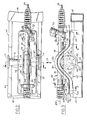
- Fig.1 is a top plan view of a vehicle four-wheel drive chassis frame and power train installation, with parts broken away, according to the invention;
- Fig. 2 is an enlarged fragmentary top plan view of the front crossbeam reinforcement bridge shown in Fig. 1;
- Fig. 3 is a fragmentary side elevational view, partly in section, taken in the direction of arrow ¨3¨ in Fig. 2;
- Fig. 4 is a fragmentary cross-sectional view taken substantially on the line 4-4 of Fig. 2, with portions shown in elevation;
- Fig. 5 is an enlarged cross-sectional view of the structural bridge member taken on line 5-5 of Fig. 3;
- Fig. 6 is an enlarged cross-sectional view of the structural bridge member taken on line 6-6 of Fig. 3; and
- Fig. 7 is an enlarged cross-sectional view taken on the line 7-7 of Fig. 3.
- Turning now to the drawings and more particularly to Fig. 1, a vehicle with which the structure of the present invention can be used, includes front and rear sets of
wheels off case 14. - The power take-
off case 14 drivably connects the transmission output (not shown) to a longitudinally extending rear axle power take-off shaft 16 universally connected bycarden joint 17 to a forward angledpropeller shaft assembly 18 and thence to rear longitudinal propeller shaft assembly 20. The rear propeller shaft assembly 20 is connected to a rear axle drive gear unit enclosed inhousing 22 rotatinghalf shafts 24 driving the rear set ofwheels 12. - A
rear axle assembly 25, disclosed in U. S. Pat. 4,533,157 issued Aug. 6, 1985, to Hornle et al., is shown supporting therear wheels 12 provided aft of thegear unit housing 22. The power take-off case 14 includes a front interwheel gear unit (not shown) rotatingfront half shafts wheels 10. - As seen in Fig. 1
vehicle frame 30 includes left 32 and right 34 side frame members, in the form of longitudinal box-section rails, interconnected by a series of transverse crossmembers numbered consecutively 35, 36, 37,38 and 39 from front to rear. A forward crossbeam assembly, generally indicated at 40, includes arcuate U-shaped left andright transition members like crossmember 44. Fig. 4 shows thecrossmember 44 having an inverted channel-shaped longitudinal section with its leading edge reverse bent to form with a hollow transversely extending box-section 46. - With reference to Fig. 2 and 3, to accommodate the power take-off longitudinal
drive shaft portion 16 together withforward connector housing 47 thecrossbeam assembly crossmember 44 upper surface is preformed with an upwardly concavearcuate depression 48 as viewed in transverse profile. Thedepression 48 defines a thinned valley portion 49 (Fig. 3) substantially aligned on the vehicle longitudinally extending vertical plane of symmetry which includes the dimension line "H1". It will be noted that thevalley portion 49 has a reduced minimum cross-sectional height "H1" in comparison to the height "H2" of the adjacent outboard portions of thecrossmember 44. In the disclosed embodiment the dimension "H1" is about one-half the dimension "H2". - In Figs 2 and 3 it will be seen that the
crossbeam assembly 40 also comprises a support bridge member, generally indicated at 50, adapted to both reinforce the crossmember thinnedvalley portion 49 and support a transverse tube portion of frontwheel steering assembly 52. Thebridge member 50 is in the form of a hollow, sinusoidal-shaped, elongated structural member fabricated of upper 54 and lower 56 half-shells. The upper downwardly opening half-shell 54 and the lower upwardly opening half-shell 56 are secured together by bonding or welding theirperipheral flanges weld line 62 shown in Fig. 5. In the disclosed form the bridge member half-shells - As seen in Fig. 3 the
bridge member 50 comprises outwardly extendingco-planer end portions crossmember 44 at abuttingflush surface areas 68 and 70. With reference to Figs. 2 and 4 it will be seen that thebridge member 50 further comprises an intermediate or central arched bifurcated portion defined by a pair of upwardly bowed fore 72 andaft 74 parallel arched branch sections. Thebranch sections open channel 76 extending between a pair of spaced upwardly concave or U-shaped contoured saddle-shaped portions concave depression 48, together with the sinusoidal shaped pair of bridgearched branch sections passageway 82 through which the longitudinaldrive shaft portion 16 extends. - As best seen in Figs. 2 and 3 the
steering assembly 52 for the vehiclefront wheels 10 includes transversely extending intermediatetubular portion 84 enclosing an inner steering rod 85 (Fig. 5). The steering assembly outertubular portion 84 is adapted for positioning in the transverseopen channel 76. Figs. 3 and 4 show the steering assemblytubular portion 84 located vertically belowpeaks arched branch sections bridge member 50 supports the steering assembly transversetubular portion 84 within the confines of theopen channel 76 while allowing is passage therethrough. - With reference to Fig. 7 the steering
tubular portion 84 has its one end secured to the crossbeamassembly bridge member 50 by a pair of integral attachment legs 90, each formed with a right-angled foot 92, adjacent steering column 93 (Figs. 2 and 3). Eachfoot 92 has anattachment hole 94 adapted to receive amachine bolt 96 therein for threaded reception in an alignedbore 97 ofsockets 98 formed integral with an interior doubler plate 100. - With reference to Fig. 5 a
U-shaped bracket 102 is shown positioned over the outer end of thesteering tube portion 84 and formed withfoot portions attachment hole 106 receiving amachine bolt 108 for threaded reception in alignedbore 107 of asocket 110 fixed on the underside of aninterior doubler plate 112. A hat-shaped clip 114 is sized for reception within thebracket 102 withclip flanges bracket foot portions upper wall 118 of thebridge member 50. Theclip flanges bolt 108. A molded elastomeric rubber-like bushing 120 surrounds thesteering tube portion 84 and is sized for resiliently holding it within thebracket 102.Elastomeric spacer blocks 122 are retained in a compressed manner between thebridge member wall 118 and theclip 114 to support the brushing 120. - A feature of the invention is that the crossbeam
assembly bridge member 50 accommodates the steering assemblytransverse tube portion 84 in a nested manner within itsopen channel 76. In this way the subjacentlongitudinal drive shaft 16 and the upper transversely extendingsteering tube portion 84 are arranged in association with thebridge member 50 with their principal axes in orthogonal relation. Thus, as seen in Figs. 3, 4, and 5principal axis 122 of the longitudinaldrive shaft portion 16 is oriented at right angles to and below principal axis 124 (Fig. 5) of the steering assembly intermediatetubular portion 84. - Although only one embodiment of the invention has been shown and described, it is apparent that other modifications and embodiments may be made without departing from the spirit and scope of the invention as defined in the appended claims.
Claims (4)
a lower crossmember adapted to be supported between said frame side members formed with an upwardly concave arcuate shaped depression including a thinned valley portion substantially aligned on the longitudinal centerline of said chassis frame;
a transversely positioned upper bridge member formed with a bifurcated portion intermediate its outboard end extensions with each said end extension affixed to an associated underlying end portion of said crossmember, said bifurcated portion in the form of fore α aft longitudinally spaced upwardly arched branch sections, whereby said bifurcated portion overlies said crossmember thinned valley section defining a passage therebetween adapted for reception therethrough of a longitudinal portion of said drive shaft assembly; and
a transverse tube portion of said vehicle steering assembly adapted for reception in an open channel defined between said bridge member fore and aft branch sections with said tube portion adapted for attachement on said bridge member end extensions, whereby said steering assembly transverse portion is arranged in an orthogonal manner with said subjacent longitudinal drive shaft.
Applications Claiming Priority (2)
| Application Number | Priority Date | Filing Date | Title |
|---|---|---|---|
| AT3299/87 | 1987-12-15 | ||
| AT0329987A AT389090B (en) | 1987-12-15 | 1987-12-15 | CHASSIS FOR MOTOR VEHICLES WITH DRIVED FRONT AXLE |
Publications (3)
| Publication Number | Publication Date |
|---|---|
| EP0321433A2 true EP0321433A2 (en) | 1989-06-21 |
| EP0321433A3 EP0321433A3 (en) | 1990-06-13 |
| EP0321433B1 EP0321433B1 (en) | 1992-06-10 |
Family
ID=3548406
Family Applications (1)
| Application Number | Title | Priority Date | Filing Date |
|---|---|---|---|
| EP88890279A Expired EP0321433B1 (en) | 1987-12-15 | 1988-11-11 | Frame crossbeam assembly for all-wheel drive vehicle |
Country Status (5)
| Country | Link |
|---|---|
| US (1) | US4903791A (en) |
| EP (1) | EP0321433B1 (en) |
| JP (1) | JPH0771896B2 (en) |
| AT (1) | AT389090B (en) |
| DE (1) | DE3871923T2 (en) |
Cited By (2)
| Publication number | Priority date | Publication date | Assignee | Title |
|---|---|---|---|---|
| US6237304B1 (en) | 1997-07-18 | 2001-05-29 | Henkel Corporation | Laminate structural bulkhead |
| EP1630073A2 (en) * | 2004-08-27 | 2006-03-01 | Audi Ag | Apparatus for fixing a carried component to a carrying component in a vehicle bodywork |
Families Citing this family (13)
| Publication number | Priority date | Publication date | Assignee | Title |
|---|---|---|---|---|
| JP3014588B2 (en) * | 1994-06-20 | 2000-02-28 | 本田技研工業株式会社 | Variable steering angle ratio steering device for vehicles |
| US5954390A (en) * | 1997-12-18 | 1999-09-21 | Chrysler Corporation | Vehicle dynamic side impact system |
| US6065559A (en) * | 1998-09-22 | 2000-05-23 | Chrysler Corporation | Support structure for a vehicle powertrain |
| US6227321B1 (en) | 1999-03-31 | 2001-05-08 | Daimlerchrysler Corporation | Structural tube for a motor vehicle unibody |
| US6712393B2 (en) | 2002-02-08 | 2004-03-30 | Volvo Trucks North America, Inc. | Tubular crossmember |
| US6905137B2 (en) | 2002-11-21 | 2005-06-14 | Volvo Trucks North America, Inc. | Composite cross member system |
| DE10315884B4 (en) * | 2003-04-08 | 2014-03-20 | Daimler Ag | Longitudinally installed four-wheel drive train |
| US7357210B2 (en) * | 2004-04-08 | 2008-04-15 | Kanzaki Kokyukoki Mfg. Co., Ltd. | Vehicle power transmission system |
| CA2528928C (en) * | 2004-12-06 | 2014-08-05 | Magna International Inc. | Integral cross member with steering gear joint |
| CN105501298B (en) * | 2015-12-28 | 2018-09-18 | 湖北航天技术研究院特种车辆技术中心 | A kind of vehicle frame |
| KR101866192B1 (en) * | 2016-12-05 | 2018-06-12 | 류형욱 | Vehicle frame assembly having a front axle being displaceable in the transverse direction |
| DE102017201811B4 (en) * | 2017-02-06 | 2022-04-28 | Ford Global Technologies, Llc | Rear axle suspension for a vehicle |
| DE102019203104A1 (en) * | 2019-03-07 | 2020-09-10 | Audi Ag | Frame device for a vehicle, in particular for a motor vehicle, and vehicle with at least one such frame device |
Citations (5)
| Publication number | Priority date | Publication date | Assignee | Title |
|---|---|---|---|---|
| US3176786A (en) * | 1962-11-13 | 1965-04-06 | Smith Corp A O | Reinforced vehicle frame for low ground clearance vehicle |
| EP0157164A1 (en) * | 1984-02-29 | 1985-10-09 | Isuzu Motors Limited | Vehicle frame |
| US4605084A (en) * | 1983-10-20 | 1986-08-12 | Harry W. Mayer | Constant mesh gear transmission |
| US4700796A (en) * | 1985-05-29 | 1987-10-20 | Dr. Ing. H.C.F. Porsche Ag | Rear axle for a motor vehicle, especially for a four-wheel drive motor vehicle |
| US4708391A (en) * | 1986-07-03 | 1987-11-24 | Mazda Motor Corporation | Rear body structure for motor vehicle |
Family Cites Families (4)
| Publication number | Priority date | Publication date | Assignee | Title |
|---|---|---|---|---|
| GB891277A (en) * | 1959-11-10 | 1962-03-14 | Daimler Benz Ag | Improvements relating to transverse frame members for motor vehicles |
| US3135347A (en) * | 1962-02-07 | 1964-06-02 | Louis M Vranyosovics | Exhaust system |
| US3534977A (en) * | 1968-08-08 | 1970-10-20 | Smith Corp A O | Universal crossmember for laddertype vehicle frame |
| US4768808A (en) * | 1987-06-22 | 1988-09-06 | American Motors Corporation | Axle beam and steering assembly mount |
-
1987
- 1987-12-15 AT AT0329987A patent/AT389090B/en not_active IP Right Cessation
-
1988
- 1988-11-02 US US07/266,181 patent/US4903791A/en not_active Expired - Fee Related
- 1988-11-11 EP EP88890279A patent/EP0321433B1/en not_active Expired
- 1988-11-11 DE DE8888890279T patent/DE3871923T2/en not_active Expired - Fee Related
- 1988-12-14 JP JP63314003A patent/JPH0771896B2/en not_active Expired - Fee Related
Patent Citations (5)
| Publication number | Priority date | Publication date | Assignee | Title |
|---|---|---|---|---|
| US3176786A (en) * | 1962-11-13 | 1965-04-06 | Smith Corp A O | Reinforced vehicle frame for low ground clearance vehicle |
| US4605084A (en) * | 1983-10-20 | 1986-08-12 | Harry W. Mayer | Constant mesh gear transmission |
| EP0157164A1 (en) * | 1984-02-29 | 1985-10-09 | Isuzu Motors Limited | Vehicle frame |
| US4700796A (en) * | 1985-05-29 | 1987-10-20 | Dr. Ing. H.C.F. Porsche Ag | Rear axle for a motor vehicle, especially for a four-wheel drive motor vehicle |
| US4708391A (en) * | 1986-07-03 | 1987-11-24 | Mazda Motor Corporation | Rear body structure for motor vehicle |
Cited By (3)
| Publication number | Priority date | Publication date | Assignee | Title |
|---|---|---|---|---|
| US6237304B1 (en) | 1997-07-18 | 2001-05-29 | Henkel Corporation | Laminate structural bulkhead |
| EP1630073A2 (en) * | 2004-08-27 | 2006-03-01 | Audi Ag | Apparatus for fixing a carried component to a carrying component in a vehicle bodywork |
| EP1630073A3 (en) * | 2004-08-27 | 2006-06-14 | Audi Ag | Apparatus for fixing a carried component to a carrying component in a vehicle bodywork |
Also Published As
| Publication number | Publication date |
|---|---|
| AT389090B (en) | 1989-10-10 |
| DE3871923T2 (en) | 1992-12-03 |
| JPH0771896B2 (en) | 1995-08-02 |
| EP0321433A3 (en) | 1990-06-13 |
| EP0321433B1 (en) | 1992-06-10 |
| JPH01197123A (en) | 1989-08-08 |
| US4903791A (en) | 1990-02-27 |
| DE3871923D1 (en) | 1992-07-16 |
| ATA329987A (en) | 1989-03-15 |
Similar Documents
| Publication | Publication Date | Title |
|---|---|---|
| US4903791A (en) | Frame crossbeam assembly for all-wheel drive vehicle | |
| US4506756A (en) | Tractor with improved frame construction | |
| EP0255749B1 (en) | Bodywork for a vehicle, in particular for an automobile, and process for manufacturing it | |
| US5364128A (en) | Rear portion structure of vehicle | |
| EP0285131B1 (en) | Automotive rear underbody structure | |
| EP1183177B1 (en) | Symmetrical dash reinforcement | |
| US5497924A (en) | Roof rack rail support foot for automotive vehicles | |
| KR20040072628A (en) | Impact force relieving structure in steering device of car | |
| CN101730641A (en) | A vehicle frame | |
| CN111891219B (en) | Outer connected system of many suspensions on electric automobile | |
| JPS62125956A (en) | Underbody of automobile | |
| JPS6329606Y2 (en) | ||
| US20110198890A1 (en) | Closed-section structural member for a vehicle | |
| EP0426635B1 (en) | A bearing arrangement for a propeller shaft of a commercial vehicle | |
| CA2528928C (en) | Integral cross member with steering gear joint | |
| JPH0189275U (en) | ||
| JPS6349420Y2 (en) | ||
| RU17507U1 (en) | CHASSIS BUS (OPTIONS) | |
| JPH0514894Y2 (en) | ||
| KR970002612Y1 (en) | Connecting structure of front panel for a car | |
| JPH075081B2 (en) | Steering device for four-wheel drive vehicle | |
| JPH0351272Y2 (en) | ||
| JPS6418920U (en) | ||
| KR200193850Y1 (en) | Front Side Members for Four Wheel Drive Vehicles | |
| JPS6114937Y2 (en) |
Legal Events
| Date | Code | Title | Description |
|---|---|---|---|
| PUAI | Public reference made under article 153(3) epc to a published international application that has entered the european phase |
Free format text: ORIGINAL CODE: 0009012 |
|
| AK | Designated contracting states |
Kind code of ref document: A2 Designated state(s): BE DE FR GB IT NL SE |
|
| PUAL | Search report despatched |
Free format text: ORIGINAL CODE: 0009013 |
|
| AK | Designated contracting states |
Kind code of ref document: A3 Designated state(s): BE DE FR GB IT NL SE |
|
| 17P | Request for examination filed |
Effective date: 19900521 |
|
| 17Q | First examination report despatched |
Effective date: 19910404 |
|
| ITF | It: translation for a ep patent filed |
Owner name: DE DOMINICIS & MAYER S.R.L. |
|
| GRAA | (expected) grant |
Free format text: ORIGINAL CODE: 0009210 |
|
| AK | Designated contracting states |
Kind code of ref document: B1 Designated state(s): BE DE FR GB IT NL SE |
|
| REF | Corresponds to: |
Ref document number: 3871923 Country of ref document: DE Date of ref document: 19920716 |
|
| ET | Fr: translation filed | ||
| PLBE | No opposition filed within time limit |
Free format text: ORIGINAL CODE: 0009261 |
|
| STAA | Information on the status of an ep patent application or granted ep patent |
Free format text: STATUS: NO OPPOSITION FILED WITHIN TIME LIMIT |
|
| 26N | No opposition filed | ||
| EAL | Se: european patent in force in sweden |
Ref document number: 88890279.8 |
|
| PGFP | Annual fee paid to national office [announced via postgrant information from national office to epo] |
Ref country code: GB Payment date: 19951016 Year of fee payment: 8 |
|
| PGFP | Annual fee paid to national office [announced via postgrant information from national office to epo] |
Ref country code: NL Payment date: 19951019 Year of fee payment: 8 Ref country code: FR Payment date: 19951019 Year of fee payment: 8 |
|
| PGFP | Annual fee paid to national office [announced via postgrant information from national office to epo] |
Ref country code: BE Payment date: 19951024 Year of fee payment: 8 |
|
| PGFP | Annual fee paid to national office [announced via postgrant information from national office to epo] |
Ref country code: SE Payment date: 19951026 Year of fee payment: 8 |
|
| PG25 | Lapsed in a contracting state [announced via postgrant information from national office to epo] |
Ref country code: GB Effective date: 19961111 |
|
| PG25 | Lapsed in a contracting state [announced via postgrant information from national office to epo] |
Ref country code: SE Effective date: 19961112 |
|
| PG25 | Lapsed in a contracting state [announced via postgrant information from national office to epo] |
Ref country code: BE Effective date: 19961130 |
|
| BERE | Be: lapsed |
Owner name: STEYR-DAIMLER-PUCH A.G. Effective date: 19961130 |
|
| PG25 | Lapsed in a contracting state [announced via postgrant information from national office to epo] |
Ref country code: NL Effective date: 19970601 |
|
| GBPC | Gb: european patent ceased through non-payment of renewal fee |
Effective date: 19961111 |
|
| PG25 | Lapsed in a contracting state [announced via postgrant information from national office to epo] |
Ref country code: FR Effective date: 19970731 |
|
| NLV4 | Nl: lapsed or anulled due to non-payment of the annual fee |
Effective date: 19970601 |
|
| EUG | Se: european patent has lapsed |
Ref document number: 88890279.8 |
|
| REG | Reference to a national code |
Ref country code: FR Ref legal event code: ST |
|
| PGFP | Annual fee paid to national office [announced via postgrant information from national office to epo] |
Ref country code: DE Payment date: 20031103 Year of fee payment: 16 |
|
| PG25 | Lapsed in a contracting state [announced via postgrant information from national office to epo] |
Ref country code: DE Free format text: LAPSE BECAUSE OF NON-PAYMENT OF DUE FEES Effective date: 20050601 |
|
| PG25 | Lapsed in a contracting state [announced via postgrant information from national office to epo] |
Ref country code: IT Free format text: LAPSE BECAUSE OF NON-PAYMENT OF DUE FEES;WARNING: LAPSES OF ITALIAN PATENTS WITH EFFECTIVE DATE BEFORE 2007 MAY HAVE OCCURRED AT ANY TIME BEFORE 2007. THE CORRECT EFFECTIVE DATE MAY BE DIFFERENT FROM THE ONE RECORDED. Effective date: 20051111 |