EP0321344B1 - Bolt-retaining device for a turbo machine - Google Patents
Bolt-retaining device for a turbo machine Download PDFInfo
- Publication number
- EP0321344B1 EP0321344B1 EP88403191A EP88403191A EP0321344B1 EP 0321344 B1 EP0321344 B1 EP 0321344B1 EP 88403191 A EP88403191 A EP 88403191A EP 88403191 A EP88403191 A EP 88403191A EP 0321344 B1 EP0321344 B1 EP 0321344B1
- Authority
- EP
- European Patent Office
- Prior art keywords
- head cover
- bolt head
- bolt
- bush
- screw
- Prior art date
- Legal status (The legal status is an assumption and is not a legal conclusion. Google has not performed a legal analysis and makes no representation as to the accuracy of the status listed.)
- Expired - Lifetime
Links
- 238000011144 upstream manufacturing Methods 0.000 claims description 4
- 238000009423 ventilation Methods 0.000 claims description 3
- 210000002105 tongue Anatomy 0.000 claims 3
- 239000007789 gas Substances 0.000 description 3
- 230000000712 assembly Effects 0.000 description 1
- 238000000429 assembly Methods 0.000 description 1
- 230000000903 blocking effect Effects 0.000 description 1
- 230000006866 deterioration Effects 0.000 description 1
- 230000005489 elastic deformation Effects 0.000 description 1
- 238000012423 maintenance Methods 0.000 description 1
- 230000014759 maintenance of location Effects 0.000 description 1
- 238000004519 manufacturing process Methods 0.000 description 1
- 239000002184 metal Substances 0.000 description 1
- 238000000034 method Methods 0.000 description 1
- 230000002028 premature Effects 0.000 description 1
Images

Classifications
-
- F—MECHANICAL ENGINEERING; LIGHTING; HEATING; WEAPONS; BLASTING
- F01—MACHINES OR ENGINES IN GENERAL; ENGINE PLANTS IN GENERAL; STEAM ENGINES
- F01D—NON-POSITIVE DISPLACEMENT MACHINES OR ENGINES, e.g. STEAM TURBINES
- F01D25/00—Component parts, details, or accessories, not provided for in, or of interest apart from, other groups
- F01D25/24—Casings; Casing parts, e.g. diaphragms, casing fastenings
- F01D25/243—Flange connections; Bolting arrangements
-
- F—MECHANICAL ENGINEERING; LIGHTING; HEATING; WEAPONS; BLASTING
- F01—MACHINES OR ENGINES IN GENERAL; ENGINE PLANTS IN GENERAL; STEAM ENGINES
- F01D—NON-POSITIVE DISPLACEMENT MACHINES OR ENGINES, e.g. STEAM TURBINES
- F01D5/00—Blades; Blade-carrying members; Heating, heat-insulating, cooling or antivibration means on the blades or the members
- F01D5/02—Blade-carrying members, e.g. rotors
- F01D5/06—Rotors for more than one axial stage, e.g. of drum or multiple disc type; Details thereof, e.g. shafts, shaft connections
- F01D5/066—Connecting means for joining rotor-discs or rotor-elements together, e.g. by a central bolt, by clamps
-
- F—MECHANICAL ENGINEERING; LIGHTING; HEATING; WEAPONS; BLASTING
- F16—ENGINEERING ELEMENTS AND UNITS; GENERAL MEASURES FOR PRODUCING AND MAINTAINING EFFECTIVE FUNCTIONING OF MACHINES OR INSTALLATIONS; THERMAL INSULATION IN GENERAL
- F16B—DEVICES FOR FASTENING OR SECURING CONSTRUCTIONAL ELEMENTS OR MACHINE PARTS TOGETHER, e.g. NAILS, BOLTS, CIRCLIPS, CLAMPS, CLIPS OR WEDGES; JOINTS OR JOINTING
- F16B41/00—Measures against loss of bolts, nuts, or pins; Measures against unauthorised operation of bolts, nuts or pins
- F16B41/002—Measures against loss of bolts, nuts or pins
-
- F—MECHANICAL ENGINEERING; LIGHTING; HEATING; WEAPONS; BLASTING
- F05—INDEXING SCHEMES RELATING TO ENGINES OR PUMPS IN VARIOUS SUBCLASSES OF CLASSES F01-F04
- F05B—INDEXING SCHEME RELATING TO WIND, SPRING, WEIGHT, INERTIA OR LIKE MOTORS, TO MACHINES OR ENGINES FOR LIQUIDS COVERED BY SUBCLASSES F03B, F03D AND F03G
- F05B2260/00—Function
- F05B2260/30—Retaining components in desired mutual position
- F05B2260/301—Retaining bolts or nuts
-
- F—MECHANICAL ENGINEERING; LIGHTING; HEATING; WEAPONS; BLASTING
- F05—INDEXING SCHEMES RELATING TO ENGINES OR PUMPS IN VARIOUS SUBCLASSES OF CLASSES F01-F04
- F05D—INDEXING SCHEME FOR ASPECTS RELATING TO NON-POSITIVE-DISPLACEMENT MACHINES OR ENGINES, GAS-TURBINES OR JET-PROPULSION PLANTS
- F05D2260/00—Function
- F05D2260/97—Reducing windage losses
Definitions
- the present invention relates to a screw fixing device on an annular flange of a turbomachine, the screw heads being covered with an annular fairing or bolt cover.
- US-A 3,727,660 thus describes an example of application to a compressor in which a bolt cover is used, further arranged so as to ensure the retention of the elements in the event of accidental unscrewing or loss of an element for a reason damage and thus avoid such an element entrained in the gas flow stream causing damage which can be significant.
- the proposed solution despite its advantages, however, requires an overall blocking of all the bolts, which in certain applications can present drawbacks for assembly-disassembly operations, particularly during maintenance operations requiring intervention on only one screw. for example.
- a screw fixing device using an annular bolt cover is characterized in that said bolt cover carries, inside and respectively to the right of each screw, a plurality of first cylindrical sockets, of larger diameter to that of the screw heads having one end secured to the respective level of holes for access to said screws, from the face of the bolt cover opposite to said screws and each having at their second end four notches cut out which cooperate with two first tabs formed at the end of a second cylindrical sleeve disposed inside each first sleeve and comprising two second legs curved inwardly and cooperating with the screw head so as to block said screw in rotation.
- each second tabs cut out on the cylindrical flank of a second bushing, folded at a right angle and slightly deformed inwardly with respect to said bushing flank each have on its internal edge a slightly offset semicircular cutout.
- each second cylindrical sleeve has on its outer edge a cover in which an oblong hole is formed so as to allow the withdrawal, by means of a tool, of said second sleeve.
- the turbomachine 1 shown diagrammatically in FIG. 1 comprises at the turbine outlet an exhaust casing 2 on which the downstream side is fixed the ejection channel (not shown in the drawings).
- the exhaust casing 2 comprises a hub 3 carrying on the upstream side an annular flange 4 provided with threaded fixing holes 5, regularly distributed.
- These holes 5 receive screws 6 intended in particular, in the application example shown in the drawings, for fixing on said flange 4 a ventilation cover 7.
- the heads 8 of the screws 6 are covered with an annular fairing, the shape obtained from sheet metal is adapted to ensure a flow of gases in good aerodynamic conditions and which constitutes a bolt cover 9.
- the fixing device 10 consists of the bolt cover 9 and screws 6 is shown in more detail in Figures 3 to 6.
- the bolt cover 9 has on its outer face 11 fairing holes 12 for access.
- first cylindrical sockets 15 having a first end 16 integral with said external face 11, this first end 16 being, for example, in the example shown in Figures 3 to 6, welded to the circular edge 17 of said access holes 12.
- the two parts 11 and 14 of the bolt cover 9 can for example also be welded to one another to facilitate manufacture.
- the second end 18 of said first sockets 15 has four slots 19 in a slot.
- each first socket 15 is placed a second cylindrical socket 20 whose internal end is cut to form, on the one hand, two first legs 21 which, as can be seen in FIGS. 3 and 4, are slightly deformed outwards so as to fit into said cutouts 19 of the first socket 15 and, on the other hand, two second legs 22, one of which 22 a is shown in the lower half-view of FIG. 3, free position, folded at right angles towards the inside of the second socket 20 and slightly deformed inwardly and the other 22 b is shown in the upper half-view of FIG 3, engaged on the end 8a of the head 8 of the screw 6.
- the internal edge of each second tab 22 comprises, as can be seen in FIGS. 5 and 6, a cutout 23 in a semicircle which is slightly offset.
- the external end of the second socket 20 carries a cover 25 in which an oblong hole 26 is formed.
- the assembly method of the assembly which has just been described is as follows.
- the bolt cover 9 with internal sockets 15 being positioned on the parts to be assembled, ventilation cover 7 and annular flange 4 of the exhaust casing 2, the screws 6 are mounted and tightened in the tapped holes 5 of said flange passing through the access holes 12 as well as through fixing holes 27 drilled in the internal part 14 of the bolt cover 9 and the heads 8 of the screws 6 bearing on the edges of these holes 27.
- the second sockets 20 are then introduced towards the inside of the bolt cover 9 through the access holes 12 so as to snap the first legs 21 into the cutouts 19 of the first sockets 15 and to engage the cutouts 23 of the second legs 22 on the teeth 24 of the end 8 a of the head 8 of the screws 6.
- the teeth 24 are 12 in number and the cooperating cutouts 23 are offset by a twenty-fourth turn so to get one in guaranteed engagement of tooth 24 in cutout 23.
- the assembly obtained also retains its dismountability and intervention is made possible individually on the screws 6.
- the risks of premature wear following several assemblies / disassemblies are reduced because only an elastic deformation of the tabs of the second sleeve 20 occurs to ensure the locking of the entire fixing device.
- the bolt cover 9 further comprises on the downstream side an annular groove 28 where the upstream edges 29 of tiles 30 for thermal protection of the hub 3 of the casing are placed. exhaust 2 of the turbomachine.
Landscapes
- Engineering & Computer Science (AREA)
- General Engineering & Computer Science (AREA)
- Mechanical Engineering (AREA)
- Structures Of Non-Positive Displacement Pumps (AREA)
- Supercharger (AREA)
Description
La présente invention concerne un dispositif de fixation à vis sur une bride annulaire de turbomachine, les têtes de vis étant recouvertes d'un carénage annulaire ou cache-boulons.The present invention relates to a screw fixing device on an annular flange of a turbomachine, the screw heads being covered with an annular fairing or bolt cover.
Lorsque des vis sont utilisées pour la fixation d'un élément sur une bride annulaire, notamment dans des applications aux turbomachines, il s'avère nécessaire pour éviter des perturbations néfastes dans les écoulements aérodynamiques d'air ou de gaz, lorsque les têtes de vis sont placées dans l'écoulement, de les recouvrir d'un tel carénage annulaire ou cache-boulons.When screws are used for fixing an element on an annular flange, in particular in applications to turbomachines, it is necessary to avoid harmful disturbances in the aerodynamic flows of air or gas, when the screw heads are placed in the drain, cover them with such an annular fairing or bolt covers.
US-A 3 727 660 décrit ainsi un exemple d'application à un compresseur dans lequel un cache-boulons est utilisé, aménagé en outre de manière à assurer la rétention des éléments en cas de dévissage accidentel ou perte d'un élément pour une raison quelconque et à éviter ainsi qu'un tel élément entraîné dans la veine de circulation des gaz ne cause des dommages qui peuvent être importants. La solution proposée, malgré ses avantages, impose cependant un blocage global de tous les boulons, ce qui dans certaines applications peut présenter des inconvénients pour les opérations de montage-démontage notamment lors des opérations de maintenance ne nécessitant d'intervention que sur une seule vis par exemple.US-A 3,727,660 thus describes an example of application to a compressor in which a bolt cover is used, further arranged so as to ensure the retention of the elements in the event of accidental unscrewing or loss of an element for a reason damage and thus avoid such an element entrained in the gas flow stream causing damage which can be significant. The proposed solution, despite its advantages, however, requires an overall blocking of all the bolts, which in certain applications can present drawbacks for assembly-disassembly operations, particularly during maintenance operations requiring intervention on only one screw. for example.
La solution mise en oeuvre par l'invention résoud de manière plus satisfaisante les différents problèmes posés sans présenter les inconvénients des solutions connues antérieures. Selon l'invention, un dispositif de fixation à vis utilisant un cache-boulons annulaire est caractérisé en ce que ledit cache-boulons porte, à l'intérieur et respectivement au droit de chaque vis, une pluralité de premières douilles cylindriques, de diamètre supérieur à celui des têtes de vis ayant une extrémité solidaire au niveau respectif de trous d'accès auxdites vis, de la face du cache-boulons opposée auxdites vis et comportant chacune à leur deuxième extrémité quatre découpes en créneau qui coopèrent avec deux premières pattes formées à l'extrémité d'une deuxième douille cylindrique disposée à l'intérieur de chaque première douille et comportant deux deuxièmes pattes courbées vers l'intérieur et coopérant avec la tête de vis de manière à bloquer ladite vis en rotation.The solution implemented by the invention more satisfactorily solves the various problems posed without having the drawbacks of prior known solutions. According to the invention, a screw fixing device using an annular bolt cover is characterized in that said bolt cover carries, inside and respectively to the right of each screw, a plurality of first cylindrical sockets, of larger diameter to that of the screw heads having one end secured to the respective level of holes for access to said screws, from the face of the bolt cover opposite to said screws and each having at their second end four notches cut out which cooperate with two first tabs formed at the end of a second cylindrical sleeve disposed inside each first sleeve and comprising two second legs curved inwardly and cooperating with the screw head so as to block said screw in rotation.
Avantageusement, lesdites deuxièmes pattes découpées sur le flanc cylindrique d'une deuxième douille, repliées à angle droit et légèrement déformées vers l'intérieur par rapport audit flanc de douille comportent chacune sur son bord interne une découpe en demi-cercle légèrement désaxée. En outre, chaque deuxième douille cylindrique comporte sur son bord externe un couvercle dans lequel est ménagé un trou oblong de manière à permettre le retrait, au moyen d'un outil, de ladite deuxième douille.Advantageously, said second tabs cut out on the cylindrical flank of a second bushing, folded at a right angle and slightly deformed inwardly with respect to said bushing flank each have on its internal edge a slightly offset semicircular cutout. In addition, each second cylindrical sleeve has on its outer edge a cover in which an oblong hole is formed so as to allow the withdrawal, by means of a tool, of said second sleeve.
D'autres caractéristiques et avantages de l'invention seront mieux compris à la lecture de la description qui va suivre d'un mode de réalisation de l'invention, en référence aux dessins annexés sur lesquels:
- la figure 1 représente une vue schématique générale d'une turbomachine sur laquelle est utilisé le dispositif de fixation à vis associées à un cache-boulons, conforme à l'invention et représenté par un arraché vu en coupe longitudinale par un plan passant par l'axe de rotation de la turbomachine,
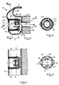
- la figure 2 montre un détail agrandi de la partie arrachée selon I de la figure 1, vue en coupe longitudinale par un plan passant par l'axe de rotation de la turbomachine.
- la figure 3 montre suivant un détail agrandi de la figure 2, le dispositif de fixation représenté aux figures 1 et 2.
- la figure 4 représente une vue, en coupe selon la ligne IV-IV de la figure 3 du dispositif de fixation représenté à la figure 3,
- la figure 5 représente une vue en bout suivant la flèche V du dispositif de fixation représenté à la figure 3 avec des parties enlevées,
- la figure 6 représente une vue, en coupe selon la ligne VI-VI de la figure 3, du dispositif de fixation représenté aux figures 3 à 5.
- FIG. 1 represents a general schematic view of a turbomachine on which the screw fastening device associated with a bolt cover is used, according to the invention and represented by a cutaway seen in longitudinal section through a plane passing through the axis of rotation of the turbomachine,
- Figure 2 shows an enlarged detail of the part cut away along I of Figure 1, seen in longitudinal section by a plane passing through the axis of rotation of the turbomachine.
- FIG. 3 shows, in an enlarged detail in FIG. 2, the fixing device shown in FIGS. 1 and 2.
- FIG. 4 represents a view, in section on line IV-IV of FIG. 3, of the fixing device shown in FIG. 3,
- FIG. 5 represents an end view along arrow V of the fastening device shown in FIG. 3 with parts removed,
- FIG. 6 represents a view, in section along the line VI-VI of FIG. 3, of the fixing device shown in FIGS. 3 to 5.
La turbomachine 1 représentée schématiquement à la figure 1 comporte en sortie de turbine un carter d'échappement 2 sur lequel côté aval est fixé le canal d'éjection (non représenté aux dessins). Comme représenté plus en détail à la figure 2, le carter d'échappement 2 comporte un moyeu 3 portant côté amont une bride annulaire 4 munie de trous taraudés 5 de fixation, régulièrement répartis. Ces trous 5 reçoivent des vis 6 destinées notamment, dans l'exemple d'application représenté aux dessins, à la fixation sur ladite bride 4 d'un couvercle de ventilation 7. Les têtes 8 des vis 6 sont recouvertes d'un carénage annulaire dont la forme obtenue à partir de tôle est adaptée pour assurer un écoulement des gaz dans de bonnes conditions aérodynamiques et qui constitue un cache-boulons 9. Le dispositif de fixation 10 conforme à l'invention et constitué du cache-boulons 9 et des vis 6 est représenté plus en détails aux figures 3 à 6. Au droit de chaque vis 6, le cache-boulons 9 comporte sur sa face externe 11 de carénage des trous 12 d'accès. Dans l'espace annulaire interne 13 du cache-boulons 9 ménagé entre sa face externe 11 et sa face interne 14 et où sont logées lesdites têtes 8 des vis 6, sont disposées des premières douilles cylindriques 15, ayant une première extrémité 16 solidaire de ladite face externe 11, cette première extrémité 16 étant, par exemple, dans l'exemple représenté aux figures 3 à 6, soudée sur le bord circulaire 17 desdits trous 12 d'accès. Les deux parties 11 et 14 du cache-boulons 9 peuvent par exemple être également soudées l'une à l'autre pour en faciliter la fabrication. La deuxième extrémité 18 desdites premières douilles 15 comporte quatre découpes 19 en créneau.The turbomachine 1 shown diagrammatically in FIG. 1 comprises at the turbine outlet an
A l'intérieur de chaque première douille 15 est placée une deuxième douille cylindrique 20 dont l'extrémité interne est découpée pour former, d'une part, deux premières pattes 21 qui, comme cela est visible sur les figures 3 et 4, sont légèrement déformées vers l'extérieur de manière à s'encastrer dans lesdites découpes 19 de première douille 15 et, d'autre part, deux deuxièmes pattes 22 dont l'une 22a est représentée à la demi-vue inférieure de la figure 3, en position libre, repliée à angle droit vers l'intérieur de la deuxième douille 20 et légèrement déformée vers l'intérieur et l'autre 22b est représentée à la demi-vue supérieure de la figure 3, engagée sur l'extrémité 8a de la tête 8 de la vis 6. Le bord interne de chaque deuxième patte 22 comporte, comme visible sur les figures 5 et 6, une découpe 23 en demi-cercle qui est légèrement désaxée. Une des dents 24 de la dentelure externe disposée sur la tête 8 de vis 6 est engagée dans ladite découpe 23 de l'une des deuxièmes pattes 22 de la deuxième douille 20. L'extrémité externe de la deuxième douille 20 porte un couvercle 25 dans lequel est ménagé un trou oblong 26.Inside each
Le mode de montage de l'ensemble qui vient d'être décrit est le suivant. Le cache-boulons 9 à douilles internes 15 étant positionné sur les pièces à assembler, couvercle de ventilation 7 et bride annulaire 4 du carter d'échappement 2, les vis 6 sont montées et serrées dans les trous taraudés 5 de ladite bride passant par les trous d'accès 12 ainsi qu'à travers des trous de fixation 27 percés dans la partie interne 14 du cache-boulons 9 et les têtes 8 des vis 6 venant en appui sur les bords de ces trous 27. Les deuxièmes douilles 20 sont alors introduites vers l'intérieur du cache-boulons 9 par les trous d'accès 12 de manière à encliqueter les premières pattes 21 dans les découpes 19 des premières douilles 15 et à engager les découpes 23 des deuxièmes pattes 22 sur les dents 24 de l'extrémité 8a de la tête 8 des vis 6. Dans le mode de réalisation représenté aux dessins à titre d'exemple, les dents 24 sont au nombre de 12 et les découpes 23 coopérantes sont désaxées d'un vingt-quatrième de tour de manière à obtenir un engagement à coup sûr de la dent 24 dans la découpe 23.The assembly method of the assembly which has just been described is as follows. The
Il résulte des dispositions décrites que la vis 6 est bloquée en rotation par l'immobilisation des dents 24 de la tête 8 de vis par les deuxièmes pattes 22 de la deuxième douille 20, elle-même bloquée par les premières pattes 21 par rapport à la première douille 15 solidaire d'un ensemble fixe. Tout desserrage accidentel est ainsi évité. Dans le cas extrême où une rupture ou détérioration des pattes 21 permettrait le desserrage d'une vis 6, la deuxième douille 20 reste accrochée à la tête de vis 6 par l'intermédiaire des pattes 22.It follows from the arrangements described that the
L'ensemble obtenu conserve également sa démontabilité et une intervention est rendue possible unitairement sur les vis 6. En effet il suffit d'engager un outil quart de tour adapté dans le trou oblong 26 du couvercle 25 de la deuxième douille 20 et de tirer sur ladite douille 20 pour désengager à la fois les premières pattes 21 des découpes 19 de la première douille 15 et les deuxièmes pattes 22 des dents 24 de la tête 8 de vis. Les risques d'usure prématurée à la suite de plusieurs montages/démontages sont réduits du fait que seule une déformation élastique des pattes de la deuxième douille 20 intervient pour assurer le verrouillage de l'ensemble du dispositif de fixation.The assembly obtained also retains its dismountability and intervention is made possible individually on the
Dans le mode de réalisation et l'application décrits et représentés aux dessins, le cache-boulons 9 comporte en outre du côté aval une gorge annulaire 28 où se placent les bords amont 29 de tuiles 30 de protection thermique du moyeu 3 du carter d'échappement 2 de la turbomachine.In the embodiment and application described and shown in the drawings, the
Claims (5)
Applications Claiming Priority (2)
| Application Number | Priority Date | Filing Date | Title |
|---|---|---|---|
| FR8717547 | 1987-12-16 | ||
| FR8717547A FR2624913B1 (en) | 1987-12-16 | 1987-12-16 | DEVICE FOR FIXING WITH A REVOLUTION PART TO AN ANNULAR FLANGE OF A TURBOMACHINE |
Publications (2)
| Publication Number | Publication Date |
|---|---|
| EP0321344A1 EP0321344A1 (en) | 1989-06-21 |
| EP0321344B1 true EP0321344B1 (en) | 1991-05-29 |
Family
ID=9357919
Family Applications (1)
| Application Number | Title | Priority Date | Filing Date |
|---|---|---|---|
| EP88403191A Expired - Lifetime EP0321344B1 (en) | 1987-12-16 | 1988-12-15 | Bolt-retaining device for a turbo machine |
Country Status (4)
| Country | Link |
|---|---|
| US (1) | US4883407A (en) |
| EP (1) | EP0321344B1 (en) |
| DE (1) | DE3863064D1 (en) |
| FR (1) | FR2624913B1 (en) |
Families Citing this family (14)
| Publication number | Priority date | Publication date | Assignee | Title |
|---|---|---|---|---|
| US5090865A (en) * | 1990-10-22 | 1992-02-25 | General Electric Company | Windage shield |
| US5259725A (en) * | 1992-10-19 | 1993-11-09 | General Electric Company | Gas turbine engine and method of assembling same |
| US5316437A (en) * | 1993-02-19 | 1994-05-31 | General Electric Company | Gas turbine engine structural frame assembly having a thermally actuated valve for modulating a flow of hot gases through the frame hub |
| DE19727680B4 (en) * | 1997-06-30 | 2004-05-19 | Zf Sachs Ag | Flywheel device with a captive device |
| US7704038B2 (en) * | 2006-11-28 | 2010-04-27 | General Electric Company | Method and apparatus to facilitate reducing losses in turbine engines |
| FR2925123A1 (en) * | 2007-12-14 | 2009-06-19 | Snecma Sa | SEALING OF BEARING SUPPORT FIXATION IN A TURBOMACHINE |
| US8292592B2 (en) * | 2008-04-02 | 2012-10-23 | United Technologies Corporation | Nosecone bolt access and aerodynamic leakage baffle |
| CH705514A1 (en) * | 2011-09-05 | 2013-03-15 | Alstom Technology Ltd | Gas channel for gas turbine, has supports, outer housing and inner housing that are equipped with refractory linings that are fastened to support structure, such that stress-free thermal expansion of linings is ensured |
| US9790919B2 (en) * | 2014-02-25 | 2017-10-17 | General Electric Company | Joint assembly for rotor blade segments of a wind turbine |
| US11274563B2 (en) * | 2016-01-21 | 2022-03-15 | General Electric Company | Turbine rear frame for a turbine engine |
| US10294808B2 (en) * | 2016-04-21 | 2019-05-21 | United Technologies Corporation | Fastener retention mechanism |
| US10494936B2 (en) * | 2016-05-23 | 2019-12-03 | United Technologies Corporation | Fastener retention mechanism |
| US10563636B2 (en) | 2017-08-07 | 2020-02-18 | General Electric Company | Joint assembly for a wind turbine rotor blade |
| IT202100009716A1 (en) | 2021-04-16 | 2022-10-16 | Ge Avio Srl | COVERING A FIXING DEVICE FOR A FLANGED JOINT |
Family Cites Families (11)
| Publication number | Priority date | Publication date | Assignee | Title |
|---|---|---|---|---|
| FR483555A (en) * | 1914-10-15 | 1917-07-20 | Henri Risser | Snap button |
| US1328488A (en) * | 1919-03-22 | 1920-01-20 | Junius A Bowden | Dust-cap and attaching means therefor |
| US2930662A (en) * | 1956-11-01 | 1960-03-29 | Bristol Aero Engines Ltd | Supporting structure for a gas turbine bearing |
| NL230456A (en) * | 1957-08-22 | |||
| US3135309A (en) * | 1961-03-01 | 1964-06-02 | Illinois Tool Works | Self-retained sheet metal fastener |
| US3737660A (en) * | 1969-10-09 | 1973-06-05 | Hida X Ray | Apparatus for taking tomograms of parabolically curved objects |
| US3727660A (en) * | 1971-02-16 | 1973-04-17 | Gen Electric | Bolt retainer and compressor employing same |
| US4190397A (en) * | 1977-11-23 | 1980-02-26 | General Electric Company | Windage shield |
| GB2057617A (en) * | 1979-09-06 | 1981-04-01 | Rolls Royce | Bolt-retaining device |
| GB2071776A (en) * | 1980-03-19 | 1981-09-23 | Rolls Royce | Stator Vane Assembly |
| US4493597A (en) * | 1982-09-07 | 1985-01-15 | Eaton Corporation | Nut lock assembly |
-
1987
- 1987-12-16 FR FR8717547A patent/FR2624913B1/en not_active Expired - Lifetime
-
1988
- 1988-12-15 EP EP88403191A patent/EP0321344B1/en not_active Expired - Lifetime
- 1988-12-15 DE DE8888403191T patent/DE3863064D1/en not_active Expired - Lifetime
- 1988-12-16 US US07/285,583 patent/US4883407A/en not_active Expired - Fee Related
Also Published As
| Publication number | Publication date |
|---|---|
| FR2624913A1 (en) | 1989-06-23 |
| FR2624913B1 (en) | 1990-04-20 |
| US4883407A (en) | 1989-11-28 |
| DE3863064D1 (en) | 1991-07-04 |
| EP0321344A1 (en) | 1989-06-21 |
Similar Documents
| Publication | Publication Date | Title |
|---|---|---|
| EP0321344B1 (en) | Bolt-retaining device for a turbo machine | |
| EP1584785B1 (en) | Balancing weight for a rotor for a rotor of a jet engine | |
| EP2060750B1 (en) | Stage of a turbine or compressor, in particular of a turbomachine | |
| CA2824379C (en) | Fan rotor and associated turbojet engine | |
| EP1811131A2 (en) | Set of fixed sectorised diffuser inserts for a turbomachine compressor | |
| CA2608402A1 (en) | Device for attaching a turbine distributor, turbine comprising same, and aircraft engine equipped with same | |
| FR2975449A1 (en) | Device for fixing annular unit on shaft of turbomachine e.g. turbojet of airplane, has nut whose one end comprises external or internal cylindrical surface of shaft, where end of nut is opposite to part of radial support annular unit | |
| EP2060751B1 (en) | Turbine or compressor stage of a jet engine | |
| FR3063308A1 (en) | CAP FOR TURBOMACHINE ROTATING INPUT COVER, COMPRISING AERODYNAMIC EXTERNAL WALL AND CONE FASTENER | |
| EP0327771B1 (en) | Bolt-retaining device for a turbomachine | |
| WO2013182797A1 (en) | Turbine engine comprising an upstream attachment means for a deoiling pipe | |
| FR3099801A1 (en) | Set for a turbomachine turbine | |
| EP1956297B1 (en) | Combustion chamber of a turbomachine | |
| EP2060744B1 (en) | Stage of a turbine or turbomachine compressor | |
| CA2364128A1 (en) | Retention system for combined or cascade blades | |
| FR2922588A1 (en) | Rotor disk or drum i.e. booster drum, for e.g. turbojet engine of airplane, has flange including orifice for mounting bolt, where rim of bolt cooperates with edges of reinforcement of flange for immobilizing bolt in orifice | |
| CA2577502C (en) | Turbine engine rotor wheel | |
| FR3063309B1 (en) | TURBOMACHINE ROTATING INLET COVER, COMPRISING AERODYNAMIC EXTERNAL WALL AND CONE CLAMP | |
| FR2654776A1 (en) | DEVICE AND SCREEN FOR REDUCING AERODYNAMIC RUPTURES DUE TO A JOINT, AND ROTATING EXHAUST DRIVING HAVING SUCH SCREEN. | |
| WO2014037653A1 (en) | Fan rotor, in particular for a turbo engine | |
| FR2991387A1 (en) | Turbo shaft engine e.g. turbojet engine, for airplane, has strip extending radially between edges of rings to ensure sealing between combustion chamber and nozzle, where edge of downstream end of rings and/or strip comprises convex surface | |
| WO2021148756A1 (en) | Fluid recovery assembly | |
| FR3102796A1 (en) | Inter-blade platforms | |
| FR2949139A1 (en) | Air-duct seal/pressure seal/gasket for e.g. turbopropeller of plane, has shaft cooperating with immobilization unit to immobilize in rotation and axial translation of ring on shaft | |
| FR3142781A1 (en) | FAN BLADE Clamping SYSTEM PROVIDED WITH A RETENTION WEDGE |
Legal Events
| Date | Code | Title | Description |
|---|---|---|---|
| PUAI | Public reference made under article 153(3) epc to a published international application that has entered the european phase |
Free format text: ORIGINAL CODE: 0009012 |
|
| 17P | Request for examination filed |
Effective date: 19890105 |
|
| AK | Designated contracting states |
Kind code of ref document: A1 Designated state(s): DE FR GB |
|
| 17Q | First examination report despatched |
Effective date: 19901017 |
|
| RAP1 | Party data changed (applicant data changed or rights of an application transferred) |
Owner name: SOCIETE NATIONALE D'ETUDE ET DE CONSTRUCTION DE MO |
|
| GRAA | (expected) grant |
Free format text: ORIGINAL CODE: 0009210 |
|
| AK | Designated contracting states |
Kind code of ref document: B1 Designated state(s): DE FR GB |
|
| REF | Corresponds to: |
Ref document number: 3863064 Country of ref document: DE Date of ref document: 19910704 |
|
| GBT | Gb: translation of ep patent filed (gb section 77(6)(a)/1977) | ||
| PLBE | No opposition filed within time limit |
Free format text: ORIGINAL CODE: 0009261 |
|
| STAA | Information on the status of an ep patent application or granted ep patent |
Free format text: STATUS: NO OPPOSITION FILED WITHIN TIME LIMIT |
|
| 26N | No opposition filed | ||
| PGFP | Annual fee paid to national office [announced via postgrant information from national office to epo] |
Ref country code: FR Payment date: 19951116 Year of fee payment: 8 |
|
| PGFP | Annual fee paid to national office [announced via postgrant information from national office to epo] |
Ref country code: GB Payment date: 19951206 Year of fee payment: 8 |
|
| PGFP | Annual fee paid to national office [announced via postgrant information from national office to epo] |
Ref country code: DE Payment date: 19960228 Year of fee payment: 8 |
|
| PG25 | Lapsed in a contracting state [announced via postgrant information from national office to epo] |
Ref country code: GB Effective date: 19961215 |
|
| GBPC | Gb: european patent ceased through non-payment of renewal fee |
Effective date: 19961215 |
|
| PG25 | Lapsed in a contracting state [announced via postgrant information from national office to epo] |
Ref country code: FR Effective date: 19970829 |
|
| PG25 | Lapsed in a contracting state [announced via postgrant information from national office to epo] |
Ref country code: DE Effective date: 19970902 |
|
| REG | Reference to a national code |
Ref country code: FR Ref legal event code: ST |