EP0321342B1 - Inertial stabilizing device for the inclination of orientable elements and telescope mirror mounted on this device - Google Patents
Inertial stabilizing device for the inclination of orientable elements and telescope mirror mounted on this device Download PDFInfo
- Publication number
- EP0321342B1 EP0321342B1 EP88403186A EP88403186A EP0321342B1 EP 0321342 B1 EP0321342 B1 EP 0321342B1 EP 88403186 A EP88403186 A EP 88403186A EP 88403186 A EP88403186 A EP 88403186A EP 0321342 B1 EP0321342 B1 EP 0321342B1
- Authority
- EP
- European Patent Office
- Prior art keywords
- axis
- inclination
- motor
- input shaft
- cradle
- Prior art date
- Legal status (The legal status is an assumption and is not a legal conclusion. Google has not performed a legal analysis and makes no representation as to the accuracy of the status listed.)
- Expired - Lifetime
Links
Images


Classifications
-
- G—PHYSICS
- G02—OPTICS
- G02B—OPTICAL ELEMENTS, SYSTEMS OR APPARATUS
- G02B27/00—Optical systems or apparatus not provided for by any of the groups G02B1/00 - G02B26/00, G02B30/00
- G02B27/64—Imaging systems using optical elements for stabilisation of the lateral and angular position of the image
- G02B27/644—Imaging systems using optical elements for stabilisation of the lateral and angular position of the image compensating for large deviations, e.g. maintaining a fixed line of sight while a vehicle on which the system is mounted changes course
Definitions
- the invention relates to a device for stabilizing the inclination, with respect to an external coordinate system, of a movable body in rotation about at least one axis of rotation relative to a support subject to inclination fluctuations relative to said coordinate system. outside. It relates more particularly, but not exclusively, to the stabilization of an optical element on board a vehicle, for example an airplane (or even a balloon, a spacecraft ...) with respect to which this optical instrument admits two perpendicular axes of rotation.
- this mirror has the function of reflecting an incident radiation along the axis of entry of the telescope, which axis is fixed relative to the plane (most often the axis of the telescope is parallel to the longitudinal axis, and to the path of the airplane, while the incident radiation is approximately transverse).
- This mirror can be oriented along two orthogonal axes, respectively perpendicular and parallel to the axis of the telescope. It is then a question of slaving with maximum precision in tilting the mirror relative to the airplane so as to maintain the alignment of its reflected radiation with the axis of the telescope, despite the vibrations of the airplane and its spatial orientation variations.
- a particular difficulty is to be solved in such a control on two axes since the variations in inclination of the plane, relative to a transverse axis perpendicular to the axis of entry of the telescope, require a correction of angle of the mirror in a 1/2 ratio while, in case of variation in inclination with respect to the longitudinal axis, the angle correction must be done in a 1/1 ratio.
- the stabilization devices known to date do not allow, by materializing an inertial reference, high-precision stabilization (one minute of angular arc, or even less) while allowing pointing at high speed (for example up to 200 ° / s).
- the stabilized platform devices are not suitable in practice for angle correction according to the aforementioned 1/2 ratio.
- the devices comprising gyroscopes linked to the instrument to be stabilized, they do not allow high aiming speeds because for this it is necessary to cause a significant precession of their gyroscopes, which harms the precision.
- the precession must be in a 1/2 ratio with the pointing angle, this results in an additional error.
- the precession is a movement resulting from an external torque which is perpendicular to the plane defined by the router axis and the axis of the disturbing torque.
- the known solutions relate to small viewfinders without slaving.
- the invention relates to a device satisfying simultaneously the above objectives, for at least one pivot axis, admitting a high aiming speed without rapid precession of the gyroscope (s) it contains.
- the originality of this invention is that the gyroscope is used as a zero instrument in a servo loop allowing a high speed of rotation to orient the optical instrument. This speed can be several hundred degrees per second.
- the gyroscope as a zero instrument makes it possible to minimize a certain number of errors, or drifts. For example, the gyroscope maintains the same relative position with respect to gravity and is therefore not disturbed, as in the case of a linked gyroscope.
- the invention also provides a device for stabilizing an optical instrument orientable around two orthogonal axes of rotation, comprising two elementary devices of the aforementioned type, one of them being linked directly to this optical instrument (for fluctuations in the support around an axis parallel to the axis of the associated on-board equipment), the other being linked to this instrument by a link (for example a planetary gear system) which achieves a 1/2 ratio.
- a link for example a planetary gear system
- the invention also provides an on-board telescope mirror equipped with such a stabilization device.
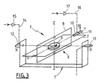
- FIG. 1 schematically represents an orientable element 1, movable in rotation about an axis of inclination X′-X ′ relative to a support 2, itself capable of exhibiting orientation fluctuations, around this axis X′-X ′, relative to an external reference frame, as well as a device 3 for stabilizing the orientable element 1 relative to its support 2.
- a tilt motor 4 is associated with the orientable element 1 for its tilt control relative to the support 2, around the axis X′-X ′.
- An encoder 5 is associated with this motor to raise, if necessary, the instantaneous angular position ⁇ ′ of the orientable element 1 relative to the support 2.
- the stabilization device 3 also called hereinafter "gyroscopic module” is shown isolated in FIG. 3: it mainly comprises a gyroscope 6 comprising a housing 7 here diagrammed by an external frame, an internal frame 8, a router 9, a motor couple 10 and a detector 11.
- the outer casing or frame 7 is linked to a cradle 1 ′ secured to the orientable element 1 by an input shaft embodying an axis XX, called the sensitive axis of the device 3.
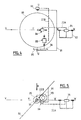
- the inner frame 8 is pivotally mounted on the outer frame 7 about an axis Y-Y, perpendicular to the axis X-X and called the exit axis or the precession axis.
- the pivoting movement of the inner frame 8 relative to the outer frame 7 is controlled by the torque motor 10; the detector 11 detects the instantaneous relative position ⁇ between the frames 7 and 8.
- the router 9 is driven in rotation, at high speed, by conventional means not shown around an axis ZZ, perpendicular to the output axis YY and called the router axis, materialized by a shaft engaged in bearings linked to the frame. interior. This axis tends to constitute an inertial reference axis.
- the router axis Z-Z is on average substantially perpendicular to the sensitive axis X-X, which coincides with the axis X′-X ′.
- the axes X-X and X′-X ′ may, as a variant, be parallel, not confused. They may not even be parallel, provided that their angle is less than 90 ° (preferably less than 45 ° or even, better, less than 15 °) and that the inclination axis is not parallel to the axis router (making an angle with it preferably between about 85 and 95 °).
- the outer frame 7, and therefore the gyroscope 6 taken as a whole, is pivotally controlled relative to the orientable element 1, around the axis XX by a motor 12, called the pointing motor. , which is associated with an angular encoder 13 adapted to take up the instantaneous angular position ⁇ of the gyroscope 6 relative to the orientable element 1.
- This pointing motor 12 has a casing which is here integral with the cradle 1 ′ of the orientable element 1 .
- This precession can also be caused directly by the torque motor 10.
- the gyroscopic module 3 also comprises connection lines with external elements.
- the pointing motor 12 receives setpoint signals by a line 14, in practice equipped with an amplifier 15.
- the torque motor 10 receives alignment signals by a line 16, also equipped with an amplifier 17
- the angular encoder 13 transmits the quantity ⁇ by a line 18.
- the encoder 5 likewise transmits the angle ⁇ ′ by a line 19.
- the detector 11 transmits the quantity ⁇ to a processing and filtering circuit 20 which generates a servo signal which, after amplification at 21, is applied to the motor 4. This constitutes a servo loop 22 of the orientable element 1 relative to the support 2.
- the gyroscopic module 3 supplemented by the above lines makes it possible to control the orientable element with various possibilities.
- any angular disturbance around the tilt axis is broken down into a component of rotation parallel to the router axis , which does not induce any reaction from the gyroscopic module, and into a component of rotation around the input shaft, which is subject to precession compensation as indicated above.
- the torque motor 10 is activated accordingly.
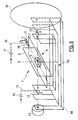
- FIGS. 4 to 9 illustrate an example of a particularly advantageous application of the gyroscopic module 3 of FIG. 1. This is the stabilization along two axes of the input mirror 30 of an on-board telescope (in practice in the nose of 'an airplane), only represented by its entry axis VV. This entry axis is in practice parallel to the longitudinal axis or thrust axis of the aircraft on which it is embarked.
- This mirror 30 is articulated around an axis UU transverse to VV on a fork 31 itself articulated around an axis WW parallel to the axis VV (in practice merged with the latter) on a support structure 32 integral with the 'plane.
- This mirror is on average oriented at 45 ° relative to the axes V-V and W-W so as to be able to reflect along the axis V-V an incident radiation R transverse to the axis of the aircraft. It is elliptical so as to present a disc surface to this radiation. In practice, it has an angular deflection of approximately 10 ° on either side of this average value of 45 ° (under the control of a motor 33) and an angular deflection of at least 90 °, or even more than 180 ° , around the WW axis (under the control of a motor 34).
- each axis U-U and W-W is associated a gyroscopic module of the type described above.
- One of them, noted 3A is associated with the W-W axis
- the other, noted 3B is associated with the U-U axis.
- These gyroscopic modules jointly constitute a device for stabilizing the mirror 30 relative to an external reference.
- the gyroscopic module 3A is directly carried by the mirror 30, that is to say that its cradle 1'A (see FIG. 7) is integral with the mirror itself.
- the input axis of his 6A gyroscope is substantially parallel to the W-W axis (at the angular displacement near the mirror relative to the fork (10 ° in practice)).
- the stabilization device 3B is indirectly carried by the mirror while its input axis is parallel to U-U. Its cradle 1′B (see FIG. 8) is in fact connected to the mirror by a mechanical connection such that this cradle rotates twice as fast around an axis parallel to U-U than the mirror itself.
- These gyroscopic modules 3A and 3B are arranged as close as possible to the center of gravity of the mirror.
- Each of these gyroscopic modules is connected to the corresponding motor 33 or 34 along lines forming servo loops 22A or 22B, the details of which appear in FIGS. 7 and 8.
- connection between the supports 2A and 2B and the associated cradles 1′A and 1′B is not, however, as direct as in FIG. 1, but the principle is the same.
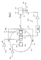
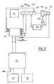
- FIG. 9 is an overall diagram of the control circuit of the stabilization devices, on which only the channel A is represented (corresponding to the elements of FIG. 7), the channel B being only sketched for reasons of visibility but being quite similar to path A.
- This circuit comprises a control, pre-pointing and tracking member 40, in practice consisting of a microprocessor, which transmits to the gyroscopic modules 3A and 3B the orders necessary for the correct orientation of the mirror relative to the axis of the telescope 41 and in return receives the measurement signals.
- a control, pre-pointing and tracking member 40 in practice consisting of a microprocessor, which transmits to the gyroscopic modules 3A and 3B the orders necessary for the correct orientation of the mirror relative to the axis of the telescope 41 and in return receives the measurement signals.
- a tachometer 42 whose speed signal is used at 21A to stabilize the control loop.
- This control member 40 is itself controlled by a computer 43 for navigation and control of the telescope.
- This computer receives various pieces of information, in particular from an inertial navigation center 44 (CIN), or even if necessary from a receiver 45 of NAVSTAR type (satellite positioning system). It also receives external information 46.
- CIN inertial navigation center
- NAVSTAR type satellite positioning system
Description
L'invention concerne un dispositif de stabilisation en inclinaison, par rapport à un repère extérieur, d'un corps mobile en rotation autour d'au moins un axe de rotation par rapport à un support sujet à des fluctuations d'inclinaison par rapport audit repère extérieur. Elle a trait plus particulièrement, mais non exclusivement, à la stabilisation d'un élément d'optique embarqué sur un véhicule, par exemple un avion (ou encore un ballon, un véhicule spatial...) par rapport auquel cet instrument d'optique admet deux axes de rotation perpendiculaires.The invention relates to a device for stabilizing the inclination, with respect to an external coordinate system, of a movable body in rotation about at least one axis of rotation relative to a support subject to inclination fluctuations relative to said coordinate system. outside. It relates more particularly, but not exclusively, to the stabilization of an optical element on board a vehicle, for example an airplane (or even a balloon, a spacecraft ...) with respect to which this optical instrument admits two perpendicular axes of rotation.
Il s'agit par exemple du miroir d'entrée d'un télescope d'observation embarqué sur un avion. Ainsi qu'on le sait ce miroir a pour fonction de réfléchir un rayonnement incident selon l'axe d'entrée du télescope, lequel axe est fixe par rapport à l'avion (le plus souvent l'axe du télescope est parallèle à l'axe longitudinal, et à la trajectoire de l'avion, tandis que le rayonnement incident est approximativement transversal). Ce miroir est orientable selon deux axes orthogonaux, respectivement perpendiculaire et parallèle à l'axe du télescope. Il s'agit alors d'asservir avec un maximum de précision en inclinaison le miroir par rapport à l'avion en sorte de maintenir l'alignement de son rayonnement réfléchi avec l'axe du télescope, malgré les vibrations de l'avion et ses variations d'orientation dans l'espace.This is for example the entrance mirror of an observation telescope on board an aircraft. As we know this mirror has the function of reflecting an incident radiation along the axis of entry of the telescope, which axis is fixed relative to the plane (most often the axis of the telescope is parallel to the longitudinal axis, and to the path of the airplane, while the incident radiation is approximately transverse). This mirror can be oriented along two orthogonal axes, respectively perpendicular and parallel to the axis of the telescope. It is then a question of slaving with maximum precision in tilting the mirror relative to the airplane so as to maintain the alignment of its reflected radiation with the axis of the telescope, despite the vibrations of the airplane and its spatial orientation variations.
Plusieurs dispositifs de stabilisation selon 1 ou 2 axes ont déjà été proposés pour répondre autant que possible à cet objectif ; certains d'entre eux sont par exemple décrits dans les documents CH-475.569, FR-2.552.893, FR-2.560.677, US-3.378.326, US-3.493.283, US-4.155.621 ou US-4.576.449. De manière plus générale on connaît également un dispositif de stabilisation d'une plate-forme inertielle de par le document US-3.499.332 ou le document SU-783.587. Tous ces systèmes font intervenir des gyroscopes ou des roues d'inertie.Several stabilization devices along 1 or 2 axes have already been proposed to meet this objective as much as possible; some of them are, for example, described in the documents CH-475.569, FR-2.552.893, FR-2.560.677, US-3.378.326, US-3.493.283, US-4.155.621 or US-4.576. 449. More generally, a device for stabilizing an inertial platform is also known from document US-3,499,332 or document SU-783,587. All of these systems involve gyroscopes or flywheels.
Une difficulté particulière est à résoudre dans un tel asservissement selon deux axes puisque les variations en inclinaison de l'avion, par rapport à un axe transversal perpendiculaire à l'axe d'entrée du télescope, demandent une correction d'angle du miroir dans un rapport 1/2 tandis que, en cas de variation en inclinaison par rapport à l'axe longitudinal la correction d'angle doit se faire dans un rapport 1/1.A particular difficulty is to be solved in such a control on two axes since the variations in inclination of the plane, relative to a transverse axis perpendicular to the axis of entry of the telescope, require a correction of angle of the mirror in a 1/2 ratio while, in case of variation in inclination with respect to the longitudinal axis, the angle correction must be done in a 1/1 ratio.
D'autre part, l'observation de cibles mobiles impose souvent de pouvoir pointer à grande vitesse un tel miroir d'entrée.On the other hand, the observation of moving targets often requires being able to point at such an input mirror at high speed.
Des problèmes de même nature sont liés à l'utilisation d'autres instruments optiques tels que, par exemple, le réflecteur orientable d'un générateur/laser embarqué sur un véhicule, le plus souvent aérien ou spatial.Problems of the same nature are linked to the use of other optical instruments such as, for example, the orientable reflector of a generator / laser on board a vehicle, most often aerial or space.
Les dispositifs de stabilisation connus à ce jour ne permettent pas, en matérialisant une référence inertielle, une stabilisation de grande précision (une minute d'arc angulaire, voire moins) tout en autorisant un pointage à grande vitesse (par exemple jusqu'à 200°/s).The stabilization devices known to date do not allow, by materializing an inertial reference, high-precision stabilization (one minute of angular arc, or even less) while allowing pointing at high speed (for example up to 200 ° / s).
Ainsi notamment les dispositifs à plate-forme stabilisée ne conviennent pas en pratique à la correction d'angle selon le rapport 1/2 précité.Thus in particular the stabilized platform devices are not suitable in practice for angle correction according to the aforementioned 1/2 ratio.
Quant aux dispositifs comportant des gyroscopes liés à l'instrument à stabiliser, ils ne permettent pas de grandes vitesses de pointage car il faut pour cela provoquer une précession importante de leurs gyroscopes, ce qui nuit à la précision. Comme en ce qui concerne un pointage autour d'un axe transversal, il faut que la précession soit dans un rapport 1/2 avec l'angle de pointage, il en découle une erreur supplémentaire.As for the devices comprising gyroscopes linked to the instrument to be stabilized, they do not allow high aiming speeds because for this it is necessary to cause a significant precession of their gyroscopes, which harms the precision. As for a pointing around a transverse axis, the precession must be in a 1/2 ratio with the pointing angle, this results in an additional error.
Il est rappelé ici que la précession est un mouvement résultant d'un couple extérieur qui est perpendiculaire au plan défini par l'axe toupie et l'axe du couple perturbateur.It is recalled here that the precession is a movement resulting from an external torque which is perpendicular to the plane defined by the router axis and the axis of the disturbing torque.
En général, les solutions connues concernent des viseurs de petites dimensions sans asservissement.In general, the known solutions relate to small viewfinders without slaving.
L'invention a pour objet un dispositif satisfaisant simultanément aux objectifs ci-dessus, pour au moins un axe de pivotement, admettant une grande vitesse de pointage sans précession rapide du ou des gyroscope(s) qu'il contient.The invention relates to a device satisfying simultaneously the above objectives, for at least one pivot axis, admitting a high aiming speed without rapid precession of the gyroscope (s) it contains.
Elle propose ainsi un dispositif de stabilisation selon la revendication 1, dont le préambule est basé sur CH-475.569.It thus proposes a stabilization device according to
Selon des dispositions préférées de l'invention:
- l'arbre d'entrée est approximativement parallèle à l'axe d'inclinaison. En pratique l'écart entre l'arbre d'entrée et l'axe d'inclinaison est inférieur à 15° ;
- l' axe de toupie est sensiblement perpendiculaire à l'axe d'inclinaison. En pratique l'axe de toupie fait un angle compris entre 85° et 95° avec l'axe d'inclinaison;
- le carter du moteur de pointage est solidaire de l'élément orientable, le rapport de transmission valant K = 1;
- la liaison de transmission est constituée d'une paire de roues dentées, engrenant l'une sur l'autre et présentant des nombres de dents égaux, respectivement portées par le support et l'arbre d'entrée, le rapport de transmission résultant étant K = 1/2.
- the input shaft is approximately parallel to the tilt axis. In practice, the difference between the input shaft and the tilt axis is less than 15 °;
- the router axis is substantially perpendicular to the tilt axis. In practice, the router axis makes an angle between 85 ° and 95 ° with the tilt axis;
- the casing of the pointing motor is integral with the orientable element, the transmission ratio being K = 1;
- the transmission link consists of a pair of toothed wheels, meshing one on the other and having equal numbers of teeth, respectively carried by the support and the input shaft, the resulting transmission ratio being K = 1/2.
L'originalité de cette invention est que le gyroscope est utilisé comme instrument de zéro dans une boucle d'asservissement permettant une vitesse de rotation importante pour orienter l'instrument optique. Cette vitesse peut être de plusieurs centaines de degrés par secondes.The originality of this invention is that the gyroscope is used as a zero instrument in a servo loop allowing a high speed of rotation to orient the optical instrument. This speed can be several hundred degrees per second.
Ce résultat est obtenu sans précession du gyroscope.This result is obtained without precession of the gyroscope.
Le fait d'utiliser le gyroscope comme instrument de zéro permet de minimiser un certain nombre d'erreurs, ou de dérives. Par exemple le gyroscope conserve la même position relative par rapport à la gravité et n'est donc pas perturbé, comme dans le cas d'un gyroscope lié.The fact of using the gyroscope as a zero instrument makes it possible to minimize a certain number of errors, or drifts. For example, the gyroscope maintains the same relative position with respect to gravity and is therefore not disturbed, as in the case of a linked gyroscope.
Indépendamment, il est donc possible de faire précessionner le gyroscope, à très faible vitesse pour effectuer des corrections angulaires, notamment dans l'un ou l'autre des cas suivants :
- recaler la référence avant la mission, ou pendant celle-ci si on dispose d'une référence externe ;
- annuler la rotation terrestre (les composantes de la rotation terrestre varient suivant la direction et la latitude de 0 à 15°/heure) ;
- suivre la verticale locale (une vitesse de 1,852 km/h (1 noeud) correspond à une rotation de 1 minute d'arc/heure.
- readjust the reference before the mission, or during the mission if there is an external reference;
- cancel the terrestrial rotation (the components of the terrestrial rotation vary according to the direction and the latitude from 0 to 15 ° / hour);
- follow the local vertical (a speed of 1,852 km / h (1 knot) corresponds to a rotation of 1 minute of arc / hour.
L'invention propose également un dispositif de stabilisation d'un instrument optique orientable autour de deux axes de rotation orthogonaux, comportant deux dispositifs élémentaires du type précité, l'un d'entre eux étant lié directement à cet instrument optique (pour les fluctuations du support autour d'un axe parallèle à l'axe de l'équipement embarqué associé), l'autre étant lié à cet instrument par une liaison (par exemple un système d'engrenage épicycloïdal) qui réalise un rapport 1/2.The invention also provides a device for stabilizing an optical instrument orientable around two orthogonal axes of rotation, comprising two elementary devices of the aforementioned type, one of them being linked directly to this optical instrument (for fluctuations in the support around an axis parallel to the axis of the associated on-board equipment), the other being linked to this instrument by a link (for example a planetary gear system) which achieves a 1/2 ratio.
L'invention propose aussi un miroir de télescope embarqué équipé d'un tel dispositif de stabilisation.The invention also provides an on-board telescope mirror equipped with such a stabilization device.
Des objets, caractéristiques et avantages de l'invention ressortent de la description qui suit, donnée à titre d'exemple illustratif non limitatif, en regard des dessins annexés sur lesquels :
- la figure 1 est un schéma en perspective d'un dispositif de stabilisation à un axe conforme à l'invention ;
- la figure 2 en est une représentation simplifiée limitée aux axes de rotation qui y interviennent ;
- la figure 3 est un schéma en perspective d'un module gyroscopique, isolé ;
- la figure 4 est une vue en élévation, à l'opposé du rayonnement incident, d'un miroir embarqué à deux axes, équipé d'un dispositif de stabilisation à deux axes conforme à l'invention ;
- la figure 5 en est une de dessus ;
- la figure 6 est un schéma en perspective d'un module gyroscopique monté rotatif, autour de son axe d'entrée sur un élément orientable ;
- la figure 7 est une vue schématique partielle du dispositif de la figure 4, détaillant une première boucle d'asservissement ;
- la figure 8 est une vue schématique analogue détaillant une seconde boucle d'asservissement, complémentaire de celle de la figure 7 ; et
- la figure 9 est une schéma électrique partiel associé au dispositif de la figure 4, ne faisant apparaître explicitement que l'une des boucles d'asservissement.
- Figure 1 is a perspective diagram of an axis stabilization device according to the invention;
- Figure 2 is a simplified representation limited to the axes of rotation involved therein;
- FIG. 3 is a perspective diagram of an isolated gyroscopic module;
- Figure 4 is an elevational view, opposite to the incident radiation, of a two-axis on-board mirror, equipped with a two-axis stabilization device according to the invention;
- Figure 5 is one from above;
- Figure 6 is a perspective diagram of a gyroscopic module rotatably mounted around its axis of entry on a steerable member;
- Figure 7 is a partial schematic view of the device of Figure 4, detailing a first control loop;
- Figure 8 is a similar schematic view detailing a second control loop, complementary to that of Figure 7; and
- Figure 9 is a partial electrical diagram associated with the device of Figure 4, only showing explicitly one of the control loops.
La figure 1 représente de façon schématique un élément orientable 1, mobile en rotation autour d'un axe d'inclinaison X′-X′ par rapport à un support 2, lui-même susceptible de présenter des fluctuations d'orientation, autour de cet axe X′-X′, par rapport à un référentiel externe, ainsi qu'un dispositif 3 de stabilisation de l'élément orientable 1 par rapport à son support 2.FIG. 1 schematically represents an
Un moteur d'inclinaison 4 est associé à l'élément orientable 1 pour sa commande en inclinaison par rapport au support 2, autour de l'axe X′-X′. Un codeur 5 est associé à ce moteur pour relever, si nécessaire, la position angulaire instantanée α′ de l'élément orientable 1 par rapport au support 2.A tilt motor 4 is associated with the
Le dispositif de stabilisation 3 aussi appelé ci-après "module gyroscopique" est représenté isolé à la figure 3 : il comporte principalement un gyroscope 6 comportant un boîtier 7 ici schématisé par un cadre extérieur, un cadre intérieur 8, une toupie 9, un moteur couple 10 et un détecteur 11.The
Le boîtier ou cadre extérieur 7 est lié à un berceau 1′ solidaire de l'élément orientable 1 par un arbre d'entrée matérialisant un axe X-X, appelé axe sensible du dispositif 3.The outer casing or
Le cadre intérieur 8 est monté pivotant sur le cadre extérieur 7 autour d'un axe Y-Y, perpendiculaire à l'axe X-X et appelé axe de sortie ou axe de précession. Le mouvement en pivotement du cadre intérieur 8 par rapport au cadre extérieur 7 est commandé par le moteur-couple 10 ; le détecteur 11 relève la position relative instantanée β entre les cadres 7 et 8.The
La toupie 9 est entraînée en rotation, à grande vitesse, par des moyens classiques non représentés autour d'un axe Z-Z, perpendiculaire à l'axe de sortie Y-Y et appelé axe de toupie, matérialisé par un arbre engagé dans des paliers liés au cadre intérieur. Cet axe tend à constituer un axe inertiel de référence.The
Dans la configuration de la figure 1, l'axe de toupie Z-Z est en moyenne sensiblement perpendiculaire à l'axe sensible X-X, lequel est confondu avec l'axe X′-X′.In the configuration of FIG. 1, the router axis Z-Z is on average substantially perpendicular to the sensitive axis X-X, which coincides with the axis X′-X ′.
Les axes X-X et X′-X′ peuvent, en variante, être parallèles non confondus. Ils peuvent même ne pas être parallèles, sous réserve que leur angle soit inférieur à 90° (de préférence inférieur à 45° voire, mieux, inférieur à 15°) et que l'axe d'inclinaison ne soit pas parallèle à l'axe de toupie (en faisant avec celui-ci un angle de préférence compris entre 85 et 95° environ).The axes X-X and X′-X ′ may, as a variant, be parallel, not confused. They may not even be parallel, provided that their angle is less than 90 ° (preferably less than 45 ° or even, better, less than 15 °) and that the inclination axis is not parallel to the axis router (making an angle with it preferably between about 85 and 95 °).
Au sein du module gyroscopique 3, le cadre extérieur 7, et donc le gyroscope 6 pris dans son ensemble, est commandé en pivotement par rapport à l'élément orientable 1, autour de l'axe X-X par un moteur 12, appelé moteur de pointage, auquel est associé un codeur angulaire 13 adapté à relever la position angulaire instantanée α du gyroscope 6 par rapport à l'élément orientable 1. Ce moteur de pointage 12 a un carter qui est ici solidaire du berceau 1′ de l'élément orientable 1.Within the
A titre de rappel, ainsi qu'on le sait, tout couple appliqué au cadre extérieur 7 autour de l'axe sensible X-X par rapport à un repère fixe dans l'espace induit, conformément au théorème du moment cinétique, une inclinaison (précession) de l'axe de toupie Z-Z autour de l'axe de sortie Y-Y aussi appelé axe de précession. Cette précession peut aussi être provoquée directement par le moteur-couple 10.As a reminder, as we know, any torque applied to the
Le module gyroscopique 3 comporte en outre des lignes de connection avec des éléments extérieurs.The
Ainsi le moteur de pointage 12 reçoit des signaux de consigne par une ligne 14, équipée en pratique d'un amplificateur 15. De même le moteur-couple 10 reçoit des signaux d'alignement par une ligne 16, également équipée d'un amplificateur 17. Le codeur angulaire 13 transmet la grandeur α par une ligne 18.Thus the pointing
Le codeur 5 transmet de même l'angle α′ par une ligne 19.The
Quant au détecteur 11, il transmet la grandeur β à un circuit 20 de traitement et de filtrage qui génère un signal d'asservissement qui, après amplification en 21, est appliqué au moteur 4. Cela constitue une boucle 22 d'asservissement de l'élément orientable 1 par rapport au support 2.As for the
Le module gyroscopique 3 complété par les lignes précitées permet d'asservir l'élément orientable avec diverses possibilités.The
En régime d'asservissement, si le support présente une variation ϑ d'orientation dans l'espace autour d'un axe parallèle à X′-X′, cette variation se transmet d'abord à l'élément orientable 1, ce qui induit par le berceau 1′ un couple autour de l'axe d'entrée X-X du module gyroscopique 3. Il en découle une précession β du gyroscope, laquelle est détectée par le détecteur 11. Le circuit 20 de la boucle d'asservissement 22 génère en conséquence un signal pour le moteur 4, qui provoque une rotation α′ de l'élément orientable par rapport au support, égale mais opposée à la perturbation ϑ. Il en découle un couple de redressement sur le gyroscope qui subit une précession qui ramène l'axe Z-Z en son orientation d'origine par rapport à l'espace.In servo control, if the support has a variation ϑ of orientation in space around an axis parallel to X′-X ′, this variation is first transmitted to the
Lorsque l'axe d'inclinaison X′-X′ fait un angle non nul avec l'arbre d'entrée, toute perturbation angulaire autour de l'axe d'inclinaison se décompose en une composante de rotation parallèle à l'axe de toupie, qui n'induit aucune réaction du module gyroscopique, et en une composante de rotation autour de l'arbre d'entrée, qui fait l'objet d'une compensation de précession comme indiqué ci-dessus.When the tilt axis X′-X ′ makes a non-zero angle with the input shaft, any angular disturbance around the tilt axis is broken down into a component of rotation parallel to the router axis , which does not induce any reaction from the gyroscopic module, and into a component of rotation around the input shaft, which is subject to precession compensation as indicated above.
Par ailleurs, lorsque, avant le début d'une phase de travail, on veut ajuster la position de l'axe de toupie dans l'espace, on active le moteur-couple 10 en conséquence.Furthermore, when, before the start of a working phase, it is desired to adjust the position of the router axis in space, the
Enfin, si l'on veut déplacer rapidement l'élément orientable 1 par rapport à son support 2, on applique un signal de consigne au moteur de pointage 12. Dès que celui-ci commence à appliquer un couple au gyroscope 6, comme précédemment la boucle d'asservissement 22 provoque une rotation relative élément orientable/support qui tend à compenser la précession induite de la toupie 9. Il en résulte que l'élément orientable 1 change d'inclinaison par rapport au support sans induire de précession du gyroscope : ce changement d'inclinaison peut donc se faire à grande vitesse et avec une grande précision.Finally, if we want to quickly move the
Les figures 4 à 9 illustrent un exemple d'application particulièrement avantageux du module gyroscopique 3 de la figure 1. Il s'agit de la stabilisation selon deux axes du miroir d'entrée 30 d'un télescope embarqué (en pratique dans le nez d'un avion), uniquement représenté par son axe d'entrée V-V. Cet axe d'entrée est en pratique parallèle à l'axe longitudinal ou axe de poussée de l'avion sur lequel il est embarqué.FIGS. 4 to 9 illustrate an example of a particularly advantageous application of the
Ce miroir 30 est articulé autour d'un axe U-U transversal à V-V sur une fourche 31 elle-même articulée autour d'un axe W-W parallèle à l'axe V-V (en pratique confondu avec ce dernier) sur une structure porteuse 32 solidaire de l'avion.This
Ce miroir est en moyenne orienté à 45° par rapport aux axes V-V et W-W en sorte de pouvoir réfléchir selon l'axe V-V un rayonnement incident R transversal à l'axe de l'avion. Il est elliptique en sorte de présenter une surface en disque à ce rayonnement. Il présente en pratique un débattement angulaire de 10° environ de part et d'autre de cette valeur moyenne de 45° (sous le contrôle d'un moteur 33) et un débattement angulaire d'au moins 90°, voire plus de 180°, autour de l'axe W-W (sous le contrôle d'un moteur 34).This mirror is on average oriented at 45 ° relative to the axes V-V and W-W so as to be able to reflect along the axis V-V an incident radiation R transverse to the axis of the aircraft. It is elliptical so as to present a disc surface to this radiation. In practice, it has an angular deflection of approximately 10 ° on either side of this average value of 45 ° (under the control of a motor 33) and an angular deflection of at least 90 °, or even more than 180 ° , around the WW axis (under the control of a motor 34).
Ainsi qu'il ressort des figures 4 et 5 à chaque axe U-U et W-W est associé un module gyroscopique du type décrit ci-dessus. L'un d'entre eux, noté 3A, est associé à l'axe W-W, et l'autre, noté 3B, est associé à l'axe U-U. Ces modules gyroscopiques constituent conjointement un dispositif de stabilisation du miroir 30 par rapport à un repère extérieur.As is apparent from Figures 4 and 5 to each axis U-U and W-W is associated a gyroscopic module of the type described above. One of them, noted 3A, is associated with the W-W axis, and the other, noted 3B, is associated with the U-U axis. These gyroscopic modules jointly constitute a device for stabilizing the
Le module gyroscopique 3A est directement porté par le miroir 30, c'est-à-dire que son berceau 1'A (voir figure 7) est solidaire du miroir lui-même. L'axe d'entrée de son gyroscope 6A est sensiblement parallèle à l'axe W-W (au débattement angulaire près du miroir par rapport à la fourche (10° en pratique) ).The
Le dispositif de stabilisation 3B est par contre indirectement porté par le miroir tandis que son axe d'entrée est parallèle à U-U. Son berceau 1′B (voir figure 8) est en fait relié au miroir par une liaison mécanique telle que ce berceau tourne deux fois plus vite autour d'un axe parallèle à U-U que le miroir lui-même.On the other hand, the
Dans l'exemple représenté (figures 4 à 6 et 8) cette liaison est assurée par une paire de roues dentées 35 et 36 présentant le même nombre de dents. L'une 35 de ces roues dentées, est solidaire d'une branche de la fourche 31 et coaxiale à U-U, tandis que l'autre 36 est solidaire du berceau 1′B (ici un boîtier) monté rotatif par des paliers 37, sur le miroir.In the example shown (Figures 4 to 6 and 8) this connection is ensured by a pair of
Ces modules gyroscopiques 3A et 3B sont disposés aussi près que possible du centre de gravité du miroir.These
Chacun de ces modules gyroscopiques est connecté au moteur 33 ou 34 correspondant selon des lignes formant des boucles d'asservissement 22A ou 22B dont le détail apparaît aux figures 7 et 8.Each of these gyroscopic modules is connected to the
Pour faire ressortir l'analogie entre ces figures et la figure 1, les éléments de ces figures correspondant à ceux de la figure 11 ont la même référence suivie de la lettre A ou B respectivement, quitte à ce que certains éléments aient une double référence.To bring out the analogy between these figures and Figure 1, the elements of these figures corresponding to those of Figure 11 have the same reference followed by the letter A or B respectively, even if some elements have a double reference.
La liaison entre les supports 2A et 2B et les berceaux associés 1′A et 1′B n'est toutefois pas aussi directe qu'à la figure 1, mais le principe en est le même.The connection between the
Ainsi à la figure 8 en ce qui concerne la deuxième boucle d'asservissement 22B et le module gyroscopique 3B, on constate que, en cas d'un perturbation angulaire ϑ de l'avion, donc de la fourche 31 mais aussi du télescope lui-même, autour d'un axe parallèle à l'axe U-U, cette perturbation se retrouve au niveau du gyroscope 6B. Il en découle, au travers de la boucle d'asservissement 22B, une rotation compensatrice du miroir par rapport à la fourche 31 qui est égale à la moitié de la perturbation ϑ, ce qui réaligne le rayonnement réfléchi selon l'axe du télescope tout en compensant complètement la précession résultant de la perturbation.Thus in FIG. 8 with regard to the
La figure 9 est un schéma d'ensemble du circuit de commande des dispositifs de stabilisation, sur lequel seule la voie A est représentée (correspondant aux éléments de la figure 7), la voie B n'étant qu'esquissée pour des raisons de visibilité mais étant tout à fait similaire à la voie A.FIG. 9 is an overall diagram of the control circuit of the stabilization devices, on which only the channel A is represented (corresponding to the elements of FIG. 7), the channel B being only sketched for reasons of visibility but being quite similar to path A.
Ce circuit comporte un organe 40 de commande, de prépointage et de poursuite, en pratique constitué d'un microprocesseur, qui transmet aux modules gyroscopiques 3A et 3B les ordres nécessaires à la bonne orientation du miroir par rapport à l'axe du télescope 41 et en reçoit en retour les signaux de mesure. On peut noter la présence d'un tachymètre 42 dont le signal de vitesse est utilisé en 21A pour stabiliser la boucle d'asservissement.This circuit comprises a control, pre-pointing and tracking
Cet organe de commande 40 est lui-même contrôlé par un calculateur 43 de navigation et de commande du télescope. Ce calculateur reçoit diverses informations, notamment d'une centrale inertielle de navigation 44 (CIN), voire le cas échéant d'un récepteur 45 de type NAVSTAR (système de localisation par satellite). Il reçoit également des informations extérieures 46.This
Un tel système global 3A-3B de stabilisation du miroir offre les avantages et particularités suivantes :
- l'élément asservi (le miroir) porte lui-même l'élément sensible aux mouvements de l'avion (le module gyroscopique) qui sert de détecteur d'erreur pour une boucle analogique de puissance (cet élément sensible étant fixé directement ou indirectement par l'élément asservi). Les mouvements de l'avion ne sont donc pas pris en compte par le microprocesseur qui peut, de ce fait, avoir une fréquence de calcul beaucoup plus faible. Les caractéristiques de la boucle analogique ainsi constituée dépendent de la réponse de l'avion aux sollicitations extérieures,
- le système n'est pas perturbé par les déformations éventuelles de l'avion,
- le système permet des déplacements angulaires de grande amplitude et de grande vitesse (environ 200°/Sec),
- les gyroscopes matérialisent la référence inertielle,
- possibilité de recalage fin de la référence inertielle en fonction de la postion de l'avion, même pendant le pointage,
- l'utilisation d'un microprocesseur permet la mise en oeuvre et la surveillance du système, avec un interface purement numérique avec le calculateur de navigation,
- la redondance des mesures d'angle donne une grande sûreté de fonctionnement et permet de déceler rapidement les anomalies de fonctionnement,
- le système est indépendant du pilotage de l'avion, ce qui augmente la sûreté de la mission,
- l'intégration du système peut être très poussée avant l'interconnexion avec le calculateur de la mission,
- cette solution fait appel à des solutions classiques ne présentant pratiquement pas d'aléas,
- les modules gyroscopiques constituent un tout pouvant être confié à un seul sous-traitant,
- sur les modules la référence inertielle est matérialisée ; il est donc possible, par exemple, d'utiliser en contrôle une référence d'horizon,
- les éléments de réglage du système sont localisés très précisément d'une part dans les filtres de structure et les gains de l'électronique de la boucle de puissance et d'autre part dans le logiciel du microprocesseur. Une part très importante de la définition du système sera acquise très rapidement et ne sera pas susceptible de varier après les essais.
- the slave element (the mirror) itself carries the element sensitive to aircraft movements (the gyroscopic module) which serves as an error detector for an analog power loop (this sensitive element being fixed directly or indirectly by the slave element). The movements of the aircraft are therefore not taken into account by the microprocessor which can, therefore, have a much lower calculation frequency. The characteristics of the analog loop thus formed depend on the response of the aircraft to external stresses,
- the system is not disturbed by possible deformations of the aircraft,
- the system allows angular displacements of great amplitude and high speed (about 200 ° / Sec),
- gyroscopes materialize the inertial reference,
- possibility of fine adjustment of the inertial reference as a function of the position of the aircraft, even during pointing,
- the use of a microprocessor allows the implementation and the monitoring of the system, with a purely digital interface with the navigation computer,
- the redundancy of the angle measurements gives a high degree of operational reliability and makes it possible to quickly detect operating anomalies,
- the system is independent of the piloting of the aircraft, which increases the security of the mission,
- the integration of the system can be very advanced before the interconnection with the mission computer,
- this solution uses conventional solutions presenting practically no hazards,
- the gyroscopic modules constitute a whole that can be entrusted to a single subcontractor,
- on the modules the inertial reference is materialized; it is therefore possible, for example, to use a horizon reference for control,
- the system adjustment elements are located very precisely on the one hand in the structure filters and the gains of the power loop electronics and on the other hand in the microprocessor software. A very important part of the system definition will be acquired very quickly and will not be likely to change after the tests.
Il va de soi que la description qui précède n'a été proposée qu'à titre d'exemple non limitatif et que de nombreuses variantes peuvent être proposées par l'homme de l'art sans sortir du cadre de l'invention. Ainsi notamment les dentures des roues dentées 35 et 36 peuvent être remplacées par tout autre moyen propre à permettre à ces roues, de diamètres égaux, de rouler sans glisser l'une sur l'autre ; en variante non représentée il s'agit d'une courroie enroulée en forme de huit sur la tranche de ces deux roues.It goes without saying that the above description has been offered only by way of nonlimiting example and that numerous variants can be proposed by those skilled in the art without departing from the scope of the invention. Thus in particular the teeth of the
Claims (11)
- Device for stabilising the inclination, relative to an external frame of reference, of an orientable member (1, 30) movable with respect to rotation about at least one first inclination axis (X'-X', U-U, W-W) under the control of a first inclination motor specific to this axis (4, 33, 34), relative to a support (2, 31, 32) itself movable with respect to this external frame of reference, this device including a first gyroscope unit (3, 3B, 3A) having a first input shaft (X-X) and a rotor axis (Z-Z), perpendicular to a precession axis (Y-Y) itself perpendicular to the input shaft, which forms a non-zero angle to this inclination axis, this input shaft being held axially and laterally with respect to the orientable member (1, 30) and being controlled in rotation upon itself by a first aiming motor (12, 12B, 12A) receiving aiming signals, the casing of which is fixed to a first cradle (1', 1'B, 1'A), the said first gyroscope unit also including a first precession detector (11, 11B, 11A) connected to the inclination motor (4, 33, 34) through a first automatic control circuit (20, 20B, 20A) adapted to apply at any time, to the inclination motor (4, 33, 34), a control signal intended to compensate for any instantaneous precession detected by the said detector, this device being characterised in that this first gyroscope unit is specific to the said inclination axis and is carried at least indirectly by the orientable member, in that the cradle for this specific unit is itself controlled in rotation with respect to the support (2, 31, 32), parallel to the input axis, by means of a transmission linkage (1'-1, 35-36, 1'A-30) determining a constant ratio K between the respective rotations of the orientable member (1, 30) and of the cradle with respect to the said support, in that the aiming motor for this specific unit is separate from the inclination motor specific to the said inclination axis, and in that the said first input shaft forms an angle of less than 90° with respect to the said inclination axis.
- Stabilisation device according to Claim 1, characterised in that the first gyroscope unit (3, 3A, 3B) is also provided, on the precession axis, with a torque motor (10, 10A, 10B) receiving alignment signals.
- Stabilisation device according to Claim 1 or Claim 2, characterised in that the input shaft (X-X) is approximately parallel to the inclination axis (X'-X', U-U, W-W), with a separation of less than 15°.
- Stabilisation device according to any one of Claims 1 to 3, characterised in that the rotor axis (Z-Z) is substantially perpendicular to the inclination axis (X'-X', U-U, W-W).
- Stabilisation device according to any one of Claims 1 to 4, characterised in that an angular encoder (13, 13A, 13B) is associated with the aiming motor (12, 12A, 12B).
- Stabilisation device according to any one of Claims 1 to 5, characterised in that the casing of the aiming motor (12, 12A) is fixed to the orientable member (1, 30), the transmission ratio having the value K = 1.
- Stabilisation device according to any one of Claims 1 to 5, intended for stabilising an orientable mirror, characterised in that the transmission linkage between the cradle (1'B) of the first gyroscope unit (3B) and the mirror (30) consists of a pair of gear wheels (35, 36) meshing with each other and having the same number of teeth, carried respectively by the support and the input cradle, the resulting transmission ratio having the value K = 1/2.
- Stabilisation device according to any one of Claims 1 to 5, characterised in that the orientable member is movable in rotation with respect to the support, under the control of a second inclination motor (34, 33), about a second inclination axis (W-W, U-U) orthogonal to the first inclination axis, a second gyroscope unit (3A, 3B) being associated with this second inclination axis and carried by the orientable member (30) so as to have its input shaft orthogonal to the first input shaft and equipped with a second aiming motor (12A, 12B), the casing of which is fixed to a second cradle (1'A, 1'B) controlled in rotation with respect to the support, parallel to the second inclination axis, by means of a second transmission linkage (1'A-30, 1'B-35-36-30) determining a second constant ratio K different from the first constant ratio, this second module including a second precession detector (11A, 11B) connected to the second inclination motor (34, 33) through a second automatic control circuit (20A, 20B).
- Stabilisation device according to Claim 8, characterised in that, the orientable member being a reflector (30) associated with on-board equipment on the support (32) and having an axis (V-V) fixed relative to the latter, this reflector being mounted so as to pivot about a transverse axis (U-U) forming the second inclination axis under the control of the second inclination motor (33), on a fork (31) mounted so as to pivot on the support, about an axis (W-W) parallel to the axis of the equipment and forming the first inclination axis, under the control of the first inclination motor (34), the first cradle (1'A) is fixed to the reflector, determining a transmission ratio K equal to 1, whilst the second cradle (1'B) is fixed to a gear wheel (36) meshing with a second gear wheel (35) with an equal number of teeth and fixed to the fork determining a transmission ratio K equal to 1/2.
- Stabilisation device according to Claim 9, characterised in that the input shaft of the first gyroscope unit is approximately parallel to the first inclination axis (W-W) whilst the input shaft of the second gyroscope unit is parallel to the second inclination axis (U-U).
- On-board telescope mirror fitted with a stabilisation device according to any one of Claims 8 to 10.
Applications Claiming Priority (2)
| Application Number | Priority Date | Filing Date | Title |
|---|---|---|---|
| FR8717642 | 1987-12-17 | ||
| FR8717642A FR2624989B1 (en) | 1987-12-17 | 1987-12-17 | INERTIAL DEVICE FOR STABILIZING IN TILT OF AN ORIENTABLE ELEMENT AND MIRROR OF ON-BOARD TELESCOPE PROVIDED WITH SUCH A DEVICE |
Publications (2)
| Publication Number | Publication Date |
|---|---|
| EP0321342A1 EP0321342A1 (en) | 1989-06-21 |
| EP0321342B1 true EP0321342B1 (en) | 1994-03-02 |
Family
ID=9357985
Family Applications (1)
| Application Number | Title | Priority Date | Filing Date |
|---|---|---|---|
| EP88403186A Expired - Lifetime EP0321342B1 (en) | 1987-12-17 | 1988-12-14 | Inertial stabilizing device for the inclination of orientable elements and telescope mirror mounted on this device |
Country Status (6)
| Country | Link |
|---|---|
| US (1) | US4973144A (en) |
| EP (1) | EP0321342B1 (en) |
| JP (1) | JPH01194009A (en) |
| CA (1) | CA1330118C (en) |
| DE (1) | DE3888132T2 (en) |
| FR (1) | FR2624989B1 (en) |
Families Citing this family (7)
| Publication number | Priority date | Publication date | Assignee | Title |
|---|---|---|---|---|
| SE467378B (en) * | 1989-08-23 | 1992-07-06 | Rolf Eric Ragnar Stroemberg | INITIATION STABILIZATION SYSTEM CARRIES ONE INSTRUMENT |
| US5256942A (en) * | 1992-05-07 | 1993-10-26 | Wood Ross C | Stabilization system for a freely rotatable platform |
| DE4238512C1 (en) * | 1992-11-14 | 1994-01-20 | Deutsche Aerospace | Inertial stabilization system |
| FR2738925B1 (en) * | 1995-09-19 | 1997-11-21 | Sagem | STABILIZED OPTICAL SIGHT DEVICE |
| SE507122C2 (en) * | 1996-10-11 | 1998-04-06 | Polytech Ab | Device for stabilizing remote sensor such as camera |
| IT1394175B1 (en) * | 2009-05-20 | 2012-06-01 | Insis Spa | OPTRONIC VISION PLATFORM WITH DOUBLE COAXIAL TREE OF ELEVATION FOR THE STABILIZATION OF THE MIRA LINE (LOS) |
| FR2974196B1 (en) | 2011-04-12 | 2014-03-07 | Ixmotion | SYSTEM FOR STABILIZING A POSITIONER WITH MOTORIZED AXES OF AN EQUIPMENT |
Family Cites Families (14)
| Publication number | Priority date | Publication date | Assignee | Title |
|---|---|---|---|---|
| FR475569A (en) * | ||||
| US3378326A (en) * | 1963-09-12 | 1968-04-16 | Bell & Howell Co | Gyroscopically controlled accidental motion compensator for optical instruments |
| FR1439999A (en) * | 1965-04-08 | 1966-05-27 | Device ensuring the stabilization and control of a line of sight, by means of two mirrors or two prisms associated with a free gyroscope, or an equivalent system | |
| DE1548371A1 (en) * | 1966-01-07 | 1971-06-09 | Bundesrep Deutschland | Panoramic telescope with image stabilization for vehicles |
| US3493283A (en) * | 1967-06-05 | 1970-02-03 | Trw Inc | Apparatus for stabilizing optical instruments |
| FR1549505A (en) * | 1967-10-31 | 1968-12-13 | ||
| US3499332A (en) * | 1968-09-25 | 1970-03-10 | Us Navy | Control system for an inertial platform |
| US3951510A (en) * | 1975-02-25 | 1976-04-20 | Westinghouse Electric Corporation | Inertially stabilized heliostat assembly |
| GB1520845A (en) * | 1976-05-07 | 1978-08-09 | Marconi Co Ltd | Arrangements including mirrors |
| US4155621A (en) * | 1977-12-29 | 1979-05-22 | Mead John A | Image stabilizer for viewing devices |
| SU783587A1 (en) * | 1979-01-08 | 1980-11-30 | Военный Инженерный Краснознаменный Институт Им. А.Ф.Можайского | Apparatus for measuring deflection speed of hydraulic stabilizer |
| DE3332416A1 (en) * | 1983-09-08 | 1985-03-21 | Messerschmitt-Bölkow-Blohm GmbH, 8000 München | ALIGNMENT MIRROR WITH STABILIZING DEVICE |
| FR2552893B1 (en) * | 1983-10-04 | 1986-07-18 | France Etat | IMPROVEMENTS ON OBSERVING DEVICES |
| FR2560677B1 (en) * | 1984-03-02 | 1986-10-24 | Sfim | GYROSTABILIZED STRUCTURE, IN PARTICULAR SUPPORT STRUCTURE OF THE MOBILE MIRROR OF A PANORAMIC PERISCOPIC VIEWFINDER |
-
1987
- 1987-12-17 FR FR8717642A patent/FR2624989B1/en not_active Expired - Fee Related
-
1988
- 1988-12-09 CA CA000585544A patent/CA1330118C/en not_active Expired - Fee Related
- 1988-12-14 EP EP88403186A patent/EP0321342B1/en not_active Expired - Lifetime
- 1988-12-14 DE DE3888132T patent/DE3888132T2/en not_active Expired - Fee Related
- 1988-12-16 JP JP63318355A patent/JPH01194009A/en active Pending
- 1988-12-19 US US07/286,751 patent/US4973144A/en not_active Expired - Fee Related
Also Published As
| Publication number | Publication date |
|---|---|
| CA1330118C (en) | 1994-06-07 |
| DE3888132T2 (en) | 1994-06-01 |
| FR2624989A1 (en) | 1989-06-23 |
| JPH01194009A (en) | 1989-08-04 |
| DE3888132D1 (en) | 1994-04-07 |
| US4973144A (en) | 1990-11-27 |
| EP0321342A1 (en) | 1989-06-21 |
| FR2624989B1 (en) | 1991-08-09 |
Similar Documents
| Publication | Publication Date | Title |
|---|---|---|
| EP0435708B1 (en) | Control method of the attitude with respect to the roll- and the gear axis for a satellite | |
| EP0142397B1 (en) | Antenna stabilisation and aiming device, especially on a ship | |
| EP0031781B1 (en) | Stabilized sighting devices for vehicles | |
| EP0493227B1 (en) | Attitude control system for a three-axis stabilized satellite on 1 small-inclination orbit | |
| EP1002716B1 (en) | Method and device for the attitude control of a satellite | |
| EP0484202A1 (en) | System for the transfer of alignment between the inertial system of a carried vehicle and that of the carrier vehicle | |
| EP0209429B1 (en) | Method and device for placing a 3-axis stabilized satellite into a geostationary orbit | |
| FR2734376A1 (en) | Airborne servo-stabilised viewfinding platform with gyro and mirror | |
| EP0321342B1 (en) | Inertial stabilizing device for the inclination of orientable elements and telescope mirror mounted on this device | |
| EP0561660B1 (en) | Method and apparatus for determining the relative position and trajectory of two spacecraft | |
| FR2686312A1 (en) | Laser-observation space vehicle, especially for wind speeds, and observation instrument designed to form part thereof | |
| FR2746494A1 (en) | SEARCHING HEAD FOR MISSILES OR PROJECTILES | |
| EP0068932B1 (en) | Sighting devices for periscopic arrangements, particulary for submarines | |
| EP1635485B1 (en) | Optical transmission method between an on-board spacecraft terminal and a distant terminal, and spacecraft adapted for said method | |
| FR2794254A1 (en) | POSITION REGULATION IN THREE AXES OF LOW ALTITUDE SATELLITE | |
| EP0333578B1 (en) | Highly dynamic gyroscope | |
| EP0794404B1 (en) | Method and apparatus to guide a missile towards a target | |
| EP0838019B1 (en) | Triaxial inertial navigation unit with several types of gyrometers | |
| FR2728339A1 (en) | METHOD AND DEVICE FOR ESTIMATING GYROMETRIC BITS | |
| FR2981149A1 (en) | Aircraft, has attitude measurement device including optical sensor that captures images of stars, where attitude measurement device measures attitude of aircraft at both day and night from images taken by sensor | |
| FR2689969A1 (en) | Highly stable aiming head for sights eg for military target - uses two reflectors, one for traversing, other for elevating sight, each mounted, respectively, on its own servo=mechanism, one of which is itself mounted on traversing assembly of other reflector | |
| FR2756375A1 (en) | METHOD AND DEVICE FOR MEASURING THE TILT OF AN AXIS LINKED TO A CARRIER | |
| FR2759974A1 (en) | Inertial wheel-stabilised satellite angular speed measuring method | |
| FR2550858A1 (en) | OPTICAL POSITION SENSOR FOR SATELLITE | |
| EP1174677A1 (en) | Stabilization system for a drone and steering system for a drone using such a stabilization system |
Legal Events
| Date | Code | Title | Description |
|---|---|---|---|
| PUAI | Public reference made under article 153(3) epc to a published international application that has entered the european phase |
Free format text: ORIGINAL CODE: 0009012 |
|
| AK | Designated contracting states |
Kind code of ref document: A1 Designated state(s): DE ES GB IT NL SE |
|
| 17P | Request for examination filed |
Effective date: 19891127 |
|
| 17Q | First examination report despatched |
Effective date: 19911105 |
|
| GRAA | (expected) grant |
Free format text: ORIGINAL CODE: 0009210 |
|
| AK | Designated contracting states |
Kind code of ref document: B1 Designated state(s): DE ES GB IT NL SE |
|
| PG25 | Lapsed in a contracting state [announced via postgrant information from national office to epo] |
Ref country code: IT Free format text: LAPSE BECAUSE OF FAILURE TO SUBMIT A TRANSLATION OF THE DESCRIPTION OR TO PAY THE FEE WITHIN THE PRE;WARNING: LAPSES OF ITALIAN PATENTS WITH EFFECTIVE DATE BEFORE 2007 MAY HAVE OCCURRED AT ANY TIME BEFORE 2007. THE CORRECT EFFECTIVE DATE MAY BE DIFFERENT FROM THE ONE RECORDED.SCRIBED TIME-LIMIT Effective date: 19940302 Ref country code: ES Free format text: THE PATENT HAS BEEN ANNULLED BY A DECISION OF A NATIONAL AUTHORITY Effective date: 19940302 Ref country code: NL Effective date: 19940302 Ref country code: SE Free format text: THE PATENT HAS BEEN ANNULLED BY A DECISION OF A NATIONAL AUTHORITY Effective date: 19940302 |
|
| REF | Corresponds to: |
Ref document number: 3888132 Country of ref document: DE Date of ref document: 19940407 |
|
| GBT | Gb: translation of ep patent filed (gb section 77(6)(a)/1977) |
Effective date: 19940408 |
|
| NLV1 | Nl: lapsed or annulled due to failure to fulfill the requirements of art. 29p and 29m of the patents act | ||
| PGFP | Annual fee paid to national office [announced via postgrant information from national office to epo] |
Ref country code: GB Payment date: 19941201 Year of fee payment: 7 |
|
| PGFP | Annual fee paid to national office [announced via postgrant information from national office to epo] |
Ref country code: DE Payment date: 19941224 Year of fee payment: 7 |
|
| PLBE | No opposition filed within time limit |
Free format text: ORIGINAL CODE: 0009261 |
|
| STAA | Information on the status of an ep patent application or granted ep patent |
Free format text: STATUS: NO OPPOSITION FILED WITHIN TIME LIMIT |
|
| 26N | No opposition filed | ||
| PG25 | Lapsed in a contracting state [announced via postgrant information from national office to epo] |
Ref country code: GB Effective date: 19951214 |
|
| GBPC | Gb: european patent ceased through non-payment of renewal fee |
Effective date: 19951214 |
|
| PG25 | Lapsed in a contracting state [announced via postgrant information from national office to epo] |
Ref country code: DE Effective date: 19960903 |