EP0321235B1 - Aufblasbares Boot mit starrem Bootskörper - Google Patents
Aufblasbares Boot mit starrem Bootskörper Download PDFInfo
- Publication number
- EP0321235B1 EP0321235B1 EP88311865A EP88311865A EP0321235B1 EP 0321235 B1 EP0321235 B1 EP 0321235B1 EP 88311865 A EP88311865 A EP 88311865A EP 88311865 A EP88311865 A EP 88311865A EP 0321235 B1 EP0321235 B1 EP 0321235B1
- Authority
- EP
- European Patent Office
- Prior art keywords
- tube
- plate
- hull
- boat
- Prior art date
- Legal status (The legal status is an assumption and is not a legal conclusion. Google has not performed a legal analysis and makes no representation as to the accuracy of the status listed.)
- Expired - Lifetime
Links
Images
Classifications
-
- B—PERFORMING OPERATIONS; TRANSPORTING
- B63—SHIPS OR OTHER WATERBORNE VESSELS; RELATED EQUIPMENT
- B63B—SHIPS OR OTHER WATERBORNE VESSELS; EQUIPMENT FOR SHIPPING
- B63B7/00—Collapsible, foldable, inflatable or like vessels
- B63B7/06—Collapsible, foldable, inflatable or like vessels having parts of non-rigid material
- B63B7/08—Inflatable
- B63B7/082—Inflatable having parts of rigid material
Definitions
- This invention relates to a rigid-hulled inflatable boat according to the first part of claim 1.
- the boats to which this invention is applicable are commonly known as rigid-hull inflatable boats, and have an inflatable tube wall or "buoyancy tube” attached to the upper rim of a rigid hull.
- Many methods of attaching the tube(s) to the hull are known; some provide a removable attachment, others a permanent one. Removable attachments are preferred as they permit much easier repair or replacement of the tube(s) without the need to take the boat out of service for long periods.
- the present invention is characterized by the features of the characterizing part of claim 1.
- the plates are attached to the tube by location in a pocket, and the plates are releasably secured to the hull by securing means penetrating the external wall of the pockets.
- the securing means comprises at least one nut and bolt or like clamping arrangement, such that the plate can simply be screwed onto the hull, and unscrewed when desired.
- the nut and bolt may both be separate from the plate and hull, in which case they are screwed together through matching holes or slots provided in the plate, sleeve and hull respectively.
- one half of the nut and bolt is permanently attached to the plate.
- This may be a screw-threaded stud projecting from the plate through the pocket, the stud being inserted through a hole or slot in the hull and then clamped by a nut; or alternatively it may be a screw-threaded insert provided in the plate for receiving a bolt passed through respective holes or slots in the hull and sleeve.
- the buoyancy tube has a plurality of plates extending successively along its length, each of which is individually secured to the hull in one of the manners described above.
- the plates are generally planar, but may be shaped to correspond more closely to the contours of the hull portion to which they are attached.
- This hull portion usually comprises a substantially horizontal flange extending around the rim of the hull.
- the plates may be loose fitting in a sleeve, which extends around the length of the tube to form a pocket, so that they can be removed if desired when not secured to the hull.
- the plates are permanently bonded to both the tube and pocket (although it is possible for some plates to be permanently attached and others loose).
- the above arrangement enables rapid removal and replacement of a buoyancy tube, by simply undoing the securing means positioned along the rigid hull wall.
- a tube having a plurality of separate plates can be conveniently packed for folding, and can be easily transported.
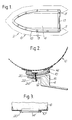
- Figure 1 shows diagrammatically a rigid inflatable boat 2 having a rigid hull portion 4 and an inflatable buoyancy tube 6 extending around the upper periphery of the hull 4.
- the tube is secured to the hull by securing means 8 extending from a series of rigid plates 10 which are attached, as will be described, to the underside of the tube along its length.
- the plates may be slightly curved to conform to the outer surface of the tube and to a flange of the hull which is to receive them.
- Specially shaped plates 11 serve to secure the tube to the boat transom 13. Typically two securing means sufficient for each plate.
- the securing arrangement is shown in detail in Figure 2.
- the tube 6 sits on a substantially horizontal flange 12 extending outwardly from the rigid hull 4, such that a plate 10 attached to the underside of the tube is aligned with the flange 12.
- the plate 10 is encased in a pocket 14 formed by sealing a layer 15 of fabric to the uninterrupted fabric outer surface of the tube 6; the plate itself may be sealed to both the fabric layer 15 and the outer surface of the tube so that it is effectively an integral part of the tube.
- Both the pocket and the tube are made preferably of conventional reinforced-elastomer material.
- plate 10 Incorporated into plate 10 is at least one threaded stud 20 which projects through a hole in the fabric layer 15 of the pocket 14.
- the plate with its stud or studs, is slid into the pocket 14 when the tube 6 is deflated and the projecting stud(s) pushed through corresponding hole(s) in the pocket wall; the plate can then be bonded to the outer surface of the tube and the layer 15 of the pocket to form a permanent attachment.
- the stud is received through a hole or slot 22 in the flange 12 of the hull, where it is secured by a complementary nut 24. As shown in Figure 1, a succession of such nuts and studs extending a long the length of the tube 6 secures the tube to the flange 12 of the hull.
- a female threaded insert could be provided which cooperates with a bolt passed up through the hull flange.
- the plate 10 may simply be provided with a hole or slot corresponding the holes or slots in the hull and pocket, and external nuts and bolts employed to clamp the plate to the flange.
- Figure 2 shows the tube 6, pocket 14 and hull flange 12 slightly spaced for the sake of clarity, in reality the plate 10 is clamped fast against the flange 12 to prevent or reduce leakage of water inwardly of the boat along the interface.
- a more effective water seal is achieved by providing on the inboard or outboard side of the boat wall, or both, a sealing flap or rib (not shown) either permanently bonded to the hull flange or to the tube itself.
- This seal can be of extruded rubber or expanded foam, or fabricated from a waterproof cloth.
- a bouyancy tube secured to a hull in this manner may be easily removed by an unskilled workman, requiring only means for unscrewing a nut or bolt. Even if the tubes are segmented i.e. a plurality of tubes lie end-to-end on each side of the boat, plates may be used. Further, the tube(s) may be packed easily when removed and deflated, owing to the relatively short length of each rigid plate. A further advantage is that existing buoyancy tubes can be converted to this method of attachment by simple addition of parts to the outer surfaces of the tubes.
- Other methods of assembling the plate to the tube include after having made the tube, laying the plates along the desired longitudinal area of the tube and simply applying the pocket-forming layer over them and bonding its edges to the tube at each side of the plate. Furthermore the surface(s) of the plate may be bonded to the tube and the pocket-forming layer in the same operation if desired. Also if desired an additional cushioning layer of elastomer may be inserted between the plate and the tube to obviate wear or rubbing on the tube due to any projections in the plate or due to the edges of the plate.
- the plate 10′ may in the deflated condition of the tube be slipped through the pocket 14′ which is relaxed by the deflation of the tube. Upon inflation of the tube it will be held firmly in the pocket with the studs 20′ pointing in the appropriate direction at positions beyond the longitudinal ends of the pocket.
- the plate is shorter than the pocket it can be fitted after the formation of the pocket if the pocket has been formed with apertures to allow the studs to penetrate outwardly.
- the studs may be held against rotation by welding to the plate or the use of coach bolts in a square aperture through the plate or by letting in a hexagonal recess at one surface of the plate into which a head of a conventional bolt fits and is holding its rotation.
- the plates may have a nut or other female securing element upon them, to be engaged by a bolt or other appropriate male securing element from the hull.
- the pockets and plates need not be at the portion of the tube which is lowermost in use. They could be at any part of the tube which is appropriate to the relationship between the tube and the hull. For example, in some patterns of hull the tube is mounted outboard of the side of the hull (see UK-A-85.16343) and in that case the plates would be secured along a vertical tangent of the tube.
Claims (7)
- Aufblasbares Boot (2) mit starrem Rumpf, das Einrichtungen zum Befestigen seines Auftriebsschlauches (6) an einem starren Teil des Bootes aufweist, wobei die Einrichtungen zumindest eine starre Verstärkungsplatte (10,10') aufweisen, die als eine Verankerung für Befestigungseinrichtungen (20,20',24) verwendet werden, wobei die Platte (10,10') außerhalb des Schlauches (6), außerhalb einer kontinuierlichen Wand davon, festgehalten wird, dadurch gekennzeichnet, daß eine Vielzahl der Platten (10,10') entlang dem Auftriebsschlauch (6) an jeder lateralen Seite des Bootes (2) angeordnet ist und sie mit dem starren Rumpf (4) des Bootes durch das Hindurchtreten von Befestigungseinrichtungen (20,20',24) durch jeweilige Öffnungen (22) einer Abfolge von Öffnungen entlang einem Flansch (12) des Rumpfes (4) an jedem der lateralen Ränder davon ineinandergreifen.
- Boot nach Anspruch 1, worin die Platten (10,10') durch eine Tasche (14) aus einem Gewebematerial (15) festgehalten werden, das mit der äußeren Oberfläche des Schlauches (6) verbunden ist.
- Boot nach Anspruch 2, worin die Befestigungseinrichtung (20) durch eine Öffnung des Gewebes (15) der Tasche (14) hindurchgeht.
- Boot nach Anspruch 2 oder 3, worin die Platten (10,10') allein durch das Einschließen durch die Tasche (14) festgehalten werden.
- Boot nach Anspruch 2 oder 3, worin die Platten mit dem Schlauch (6) und/oder der Tasche (14) verbunden sind.
- Boot nach Anspruch 4 oder 5, worin die Befestigungseinrichtung (20') jenseits eines longitudinalen Endes der Tasche (14') angeordnet ist.
- Boot nach einem der vorhergehenden Ansprüche, worin jede Platte zumindest ein Befestigungselement (22) aufweist, das in die Platten (10,10') eingebaut ist.
Applications Claiming Priority (4)
| Application Number | Priority Date | Filing Date | Title |
|---|---|---|---|
| GB878729338A GB8729338D0 (en) | 1987-12-16 | 1987-12-16 | Attachment of tubes in inflatable boats |
| GB8729338 | 1987-12-16 | ||
| GB888804182A GB8804182D0 (en) | 1987-12-16 | 1988-02-23 | Attachment of tubes in inflatable boats |
| GB8804182 | 1988-02-23 |
Publications (3)
| Publication Number | Publication Date |
|---|---|
| EP0321235A2 EP0321235A2 (de) | 1989-06-21 |
| EP0321235A3 EP0321235A3 (en) | 1989-11-15 |
| EP0321235B1 true EP0321235B1 (de) | 1993-03-17 |
Family
ID=26293205
Family Applications (1)
| Application Number | Title | Priority Date | Filing Date |
|---|---|---|---|
| EP88311865A Expired - Lifetime EP0321235B1 (de) | 1987-12-16 | 1988-12-15 | Aufblasbares Boot mit starrem Bootskörper |
Country Status (3)
| Country | Link |
|---|---|
| US (1) | US4934301A (de) |
| EP (1) | EP0321235B1 (de) |
| DE (1) | DE3879428T2 (de) |
Families Citing this family (10)
| Publication number | Priority date | Publication date | Assignee | Title |
|---|---|---|---|---|
| US5282436A (en) * | 1992-01-15 | 1994-02-01 | Hansen William M | Foam stabilized watercraft |
| US5419726A (en) * | 1993-12-17 | 1995-05-30 | Switlik Parachute Company, Inc. | Inflatable flotation raft apparatus having heated seal areas and method of assembly thereof |
| US5584260A (en) * | 1995-09-11 | 1996-12-17 | Zodiac Hurricane Technologies, Inc. | Tube attachment device for inflatable boats |
| FR2765181B1 (fr) * | 1997-06-30 | 1999-08-27 | Zodiac Int | Embase de support d'accessoires sur la paroi souple d'un corps gonflable et embarcation pneumatique ainsi equipee |
| US6024042A (en) * | 1998-02-17 | 2000-02-15 | Brunswick Corporation | Rib rigid hull inflatable boat with improved deck drainage and support construction |
| US6223677B1 (en) | 1999-10-21 | 2001-05-01 | Vanguard Boats, Inc. | Rigid inflatable boat with adaptable hull |
| US7322868B2 (en) * | 2003-11-19 | 2008-01-29 | Ross Jennifer D | Water devices and methods for making and using such devices |
| US8920206B1 (en) | 2012-02-08 | 2014-12-30 | Carolina Ip Llc | Interlocking swim noodles |
| WO2013119921A2 (en) * | 2012-02-08 | 2013-08-15 | Carolina Ip, Llc | Interlocking swim noodles |
| US9376180B2 (en) * | 2013-11-06 | 2016-06-28 | Air Cruisers Company | Raft assembly components and methods |
Family Cites Families (13)
| Publication number | Priority date | Publication date | Assignee | Title |
|---|---|---|---|---|
| US2496460A (en) * | 1946-08-10 | 1950-02-07 | Armstrong Rubber Co | Pneumatic float |
| FR1189438A (fr) * | 1958-01-02 | 1959-10-02 | L Angeviniere Soc Ind | Bateau pneumatique équipé pour recevoir un moteur |
| FR1420877A (fr) * | 1965-01-13 | 1965-12-10 | Assemblage de flotteurs pneumatiques indépendants formant un canot sans fond dans l'eau, surmonté d'un pont souple ou rigide et d'une tente habitable, le tout étant amovible | |
| FR1536498A (fr) * | 1966-07-26 | 1968-08-16 | Adamoli Resine Sint | Canot pneumatique |
| FR1549242A (de) * | 1967-08-01 | 1968-12-13 | ||
| US3490085A (en) * | 1968-06-07 | 1970-01-20 | Charles T Lewis | Inflatable boat |
| US3608112A (en) * | 1969-05-26 | 1971-09-28 | Outboard Marine Corp | Collapsible boat |
| US3566425A (en) * | 1969-09-10 | 1971-03-02 | Bonair Boats Inc | Floorboard apparatus for inflatable boats or the like |
| FR2178674A5 (de) * | 1974-12-16 | 1973-11-09 | Fahr Ag Maschf | |
| GB1589635A (en) * | 1977-09-07 | 1981-05-13 | Galt G S | Inflatable tube boat |
| EP0024401B1 (de) * | 1979-03-01 | 1984-06-20 | SOUBIE, Pierre Jean | Aufblasbare strukturen und schlauchboote mit solchen strukturen |
| IT1122315B (it) * | 1979-07-25 | 1986-04-23 | Cigognetti Edoardo | Perfezionamenti nei battelli pneumatici di medie dimensioni |
| GB2161118B (en) * | 1984-07-02 | 1988-06-22 | Avon Ind Polymers | Improved inflatable tube boat |
-
1988
- 1988-12-15 EP EP88311865A patent/EP0321235B1/de not_active Expired - Lifetime
- 1988-12-15 DE DE8888311865T patent/DE3879428T2/de not_active Expired - Fee Related
- 1988-12-15 US US07/287,827 patent/US4934301A/en not_active Expired - Fee Related
Also Published As
| Publication number | Publication date |
|---|---|
| US4934301A (en) | 1990-06-19 |
| EP0321235A3 (en) | 1989-11-15 |
| DE3879428T2 (de) | 1993-09-23 |
| DE3879428D1 (de) | 1993-04-22 |
| EP0321235A2 (de) | 1989-06-21 |
Similar Documents
| Publication | Publication Date | Title |
|---|---|---|
| US4867094A (en) | Flotation system | |
| EP0321235B1 (de) | Aufblasbares Boot mit starrem Bootskörper | |
| EP0144320B1 (de) | Wasserdichtes fussbodenfestsetzungssystem von oben erreichbar | |
| US20060189230A1 (en) | Detachable surfboard fin system | |
| CA2765008C (en) | Protective apparatus for marine structures | |
| EP0370668B1 (de) | Modularer, starrer aufblasbarer Aufbau eines Wasserfahrzeuges | |
| AU2006201967B2 (en) | A water craft inflatable fender system | |
| EP1625070B1 (de) | Schwimmendes brett für wassersport | |
| CA1309900C (en) | System for mounting accessories on inflatable structures such as boats | |
| US4628854A (en) | Securing inflatable tubes to rigid hulls | |
| EP0338836B1 (de) | Vorrichtung und Verfahren zur Befestigung von Schläuchen an Schlauchbooten | |
| US4722292A (en) | Inflatable removable keel for inflatable rubber boats | |
| CA2366159C (en) | Modular pontoon system | |
| US5584260A (en) | Tube attachment device for inflatable boats | |
| US4924796A (en) | Replaceable inflation valve | |
| US2127871A (en) | Apparatus for stopping leaks in ships | |
| GB1589635A (en) | Inflatable tube boat | |
| US5097781A (en) | Mast boot | |
| GB2162131A (en) | Improvements in or relating to buoyancy tubes | |
| CN219790444U (zh) | 一种可拆卸式充气船 | |
| US3448471A (en) | Stowages for inflatable liferafts | |
| GB2160481A (en) | Buoyancy tube assembly for marine craft | |
| US4915053A (en) | Method and apparatus for cathodic protection of marine vessels | |
| AT525759B1 (de) | Verkleidung für Antriebe von Wasserfahrzeugen | |
| CN220225196U (zh) | 充气式pvc围油栏 |
Legal Events
| Date | Code | Title | Description |
|---|---|---|---|
| PUAI | Public reference made under article 153(3) epc to a published international application that has entered the european phase |
Free format text: ORIGINAL CODE: 0009012 |
|
| AK | Designated contracting states |
Kind code of ref document: A2 Designated state(s): DE FR GB NL |
|
| PUAL | Search report despatched |
Free format text: ORIGINAL CODE: 0009013 |
|
| AK | Designated contracting states |
Kind code of ref document: A3 Designated state(s): DE FR GB NL |
|
| 17P | Request for examination filed |
Effective date: 19900328 |
|
| 17Q | First examination report despatched |
Effective date: 19910729 |
|
| RTI1 | Title (correction) | ||
| GRAA | (expected) grant |
Free format text: ORIGINAL CODE: 0009210 |
|
| AK | Designated contracting states |
Kind code of ref document: B1 Designated state(s): DE FR GB NL |
|
| REF | Corresponds to: |
Ref document number: 3879428 Country of ref document: DE Date of ref document: 19930422 |
|
| ET | Fr: translation filed | ||
| PGFP | Annual fee paid to national office [announced via postgrant information from national office to epo] |
Ref country code: GB Payment date: 19931214 Year of fee payment: 6 |
|
| PGFP | Annual fee paid to national office [announced via postgrant information from national office to epo] |
Ref country code: FR Payment date: 19931215 Year of fee payment: 6 |
|
| PGFP | Annual fee paid to national office [announced via postgrant information from national office to epo] |
Ref country code: DE Payment date: 19931220 Year of fee payment: 6 |
|
| PGFP | Annual fee paid to national office [announced via postgrant information from national office to epo] |
Ref country code: NL Payment date: 19931231 Year of fee payment: 6 |
|
| PLBE | No opposition filed within time limit |
Free format text: ORIGINAL CODE: 0009261 |
|
| STAA | Information on the status of an ep patent application or granted ep patent |
Free format text: STATUS: NO OPPOSITION FILED WITHIN TIME LIMIT |
|
| 26N | No opposition filed | ||
| PG25 | Lapsed in a contracting state [announced via postgrant information from national office to epo] |
Ref country code: GB Effective date: 19941215 |
|
| PG25 | Lapsed in a contracting state [announced via postgrant information from national office to epo] |
Ref country code: NL Effective date: 19950701 |
|
| GBPC | Gb: european patent ceased through non-payment of renewal fee |
Effective date: 19941215 |
|
| PG25 | Lapsed in a contracting state [announced via postgrant information from national office to epo] |
Ref country code: FR Effective date: 19950831 |
|
| NLV4 | Nl: lapsed or anulled due to non-payment of the annual fee |
Effective date: 19950701 |
|
| PG25 | Lapsed in a contracting state [announced via postgrant information from national office to epo] |
Ref country code: DE Effective date: 19950901 |
|
| REG | Reference to a national code |
Ref country code: FR Ref legal event code: ST |