EP0320316A2 - Positionsdetektor für Schreibstifte - Google Patents
Positionsdetektor für Schreibstifte Download PDFInfo
- Publication number
- EP0320316A2 EP0320316A2 EP88311759A EP88311759A EP0320316A2 EP 0320316 A2 EP0320316 A2 EP 0320316A2 EP 88311759 A EP88311759 A EP 88311759A EP 88311759 A EP88311759 A EP 88311759A EP 0320316 A2 EP0320316 A2 EP 0320316A2
- Authority
- EP
- European Patent Office
- Prior art keywords
- marking device
- signals
- axial position
- axis
- occurrence
- Prior art date
- Legal status (The legal status is an assumption and is not a legal conclusion. Google has not performed a legal analysis and makes no representation as to the accuracy of the status listed.)
- Withdrawn
Links
- 238000001514 detection method Methods 0.000 title 1
- 238000000034 method Methods 0.000 claims description 49
- 238000012935 Averaging Methods 0.000 claims description 16
- 230000005855 radiation Effects 0.000 claims description 10
- 238000006073 displacement reaction Methods 0.000 claims description 7
- 230000008569 process Effects 0.000 claims description 5
- 239000004065 semiconductor Substances 0.000 claims 1
- 239000003550 marker Substances 0.000 abstract 4
- 238000012937 correction Methods 0.000 description 17
- 230000006870 function Effects 0.000 description 6
- 230000000712 assembly Effects 0.000 description 5
- 238000000429 assembly Methods 0.000 description 5
- 238000010276 construction Methods 0.000 description 5
- 230000007423 decrease Effects 0.000 description 5
- 230000037361 pathway Effects 0.000 description 3
- 238000004519 manufacturing process Methods 0.000 description 2
- 230000007246 mechanism Effects 0.000 description 2
- 230000008859 change Effects 0.000 description 1
- 238000006243 chemical reaction Methods 0.000 description 1
- 239000003086 colorant Substances 0.000 description 1
- 230000007547 defect Effects 0.000 description 1
- 230000002950 deficient Effects 0.000 description 1
- 238000013461 design Methods 0.000 description 1
- 238000010438 heat treatment Methods 0.000 description 1
- 208000014674 injury Diseases 0.000 description 1
- 230000014759 maintenance of location Effects 0.000 description 1
- 238000012986 modification Methods 0.000 description 1
- 230000004048 modification Effects 0.000 description 1
- 230000004044 response Effects 0.000 description 1
- 125000006850 spacer group Chemical group 0.000 description 1
- 230000001052 transient effect Effects 0.000 description 1
- 230000008733 trauma Effects 0.000 description 1
Images



Classifications
-
- B—PERFORMING OPERATIONS; TRANSPORTING
- B43—WRITING OR DRAWING IMPLEMENTS; BUREAU ACCESSORIES
- B43L—ARTICLES FOR WRITING OR DRAWING UPON; WRITING OR DRAWING AIDS; ACCESSORIES FOR WRITING OR DRAWING
- B43L13/00—Drawing instruments, or writing or drawing appliances or accessories not otherwise provided for
- B43L13/02—Draughting machines or drawing devices for keeping parallelism
- B43L13/022—Draughting machines or drawing devices for keeping parallelism automatic
- B43L13/024—Drawing heads therefor
-
- G—PHYSICS
- G01—MEASURING; TESTING
- G01D—MEASURING NOT SPECIALLY ADAPTED FOR A SPECIFIC VARIABLE; ARRANGEMENTS FOR MEASURING TWO OR MORE VARIABLES NOT COVERED IN A SINGLE OTHER SUBCLASS; TARIFF METERING APPARATUS; MEASURING OR TESTING NOT OTHERWISE PROVIDED FOR
- G01D9/00—Recording measured values
- G01D9/40—Producing one or more recordings, each recording being produced by controlling either the recording element, e.g. stylus or the recording medium, e.g. paper roll, in accordance with two or more variables
Definitions
- the present invention relates to an apparatus and method for use in conjunction with graphics equipment incorporating controlled multiple marking devices to create displays, and more particularly, such apparatus and method for use in determining the position of the marking devices along axes of movement.
- the carriage typically is adapted to receive a pen or similar marking device from a carousel or other magazine containing a plurality of pens, then to move the pen back and forth along the Y axis in order to develop the graphics (in conjunction with the movement of the paper along the X axis), and finally to return the pen to the carousel, either in the initial location or in a new location if the carousel has subsequently rotated.
- the pen is typically disposed in a special adaptor or casing. It will be appreciated that other XY digital plotters utilize a stationary paper or chart and the pen carriage is capable of movement along both the X and Y axes.
- a further object is to provide such apparatus and method which is functionally related to the position of the marking device by electrical signals from either electro/mechanical sensors or with one or more beams of radiation.
- the apparatus generally comprises a detector assembly, disposed at a fixed axial position relative to the plotter, and means for moving a marking device relative to the detector assembly.
- the detector assembly includes means for detecting movement of the marking device relative to the detector assembly and producing signals indicative of the movement.
- the apparatus also includes means for interpreting the signals for determining an axial position of the marking device.
- the detector assembly comprises a pair of beam emitters for producing two intersecting beams of radiation in the travel path of the marking device, and a pair of associated beam detectors to detect the beams and produce first and second signals indicative of the interruptions of the beams caused by a movement of the marking device through the beams.
- the order in which the first and second signals occur and the difference in the times of occurrence of the first and second signals is functionally related to the axial position of the marking device along a first axis
- the geometry of the detector assembly and the sum of the times of occurrence of the first and second signals is functionally related to the axial position of the marking device along a second axis.
- the apparatus additionally comprises means for determining the axial position of the marking device along the first axis by the difference in the times of occurrence of the first and second signals, and for determining the axial position of the marking device along a second axis by the sum of the times of occurrence of the first and second signals.
- the third signal and the at least one additional signal are averaged to determine the time of occurrence of each of the first and second signals.
- the plurality of preselected amplitudes subsequent to the first preselected amplitude are preferably progressively increased by a fixed quantity.
- the detector assembly comprises a pair of spring sensors having an opposed pair of semicircular contacts, each facing the second axis.
- the pair of sensors comprises a pair of spring lever arms, each lever arm having mounted thereon one of the contacts and one of the displacement transducers.
- the apparatus further comprises means for summing the maxima or the first and second signals to determine the axial position of the marking device along the first axis, and for averaging the times of occurrence of the beginning and ending times of at least one of the first and second signals to determine the axial position of the marking device along the second axis.
- Such means preferably is functionally related to the axial position of the marking device along the second axis by averaging the average of the times of occurrence of the beginning and ending of the first signal and the average of the times of occurrence of the beginning and ending of the second signal.
- the axial position of the marking device along a first axis is functionally related to the geometry of the contact and a signal indicative of the deflection of the contact caused by the engagement of the marking device with the first and second sides
- the axial position of the marking device along a second axis is functionally related to the geometry of the contact and a signal indicative of the deflection of the contact caused by the engagement of the marking device with the first, second and third sides.
- a method for determining the position of multiple marking devices used with a digital plotter to create displays on a medium along axes of movement comprises the steps of providing a detector assembly disposed at a fixed axial position relative to the plotter, moving a marking device relative to the detector assembly, detecting the movement of the marking device and producing signals indicative of such movement, and interpreting the signals for determining an axial position of the marking device.
- the plotter 10 includes a housing 12 having a pivotable top 14 shown in the open position.
- a medium 16 such as a chart or paper, is fed from a supply (not shown) forwardly in the direction of arrow 18 (or forwardly and backwardly) by adjustable pinch roll/drive drum assemblies 20, and one either edge of the paper 16. It will be appreciated that the movement of the paper 16 along the axis of arrow 18 is generally considered movement along the X axis.
- the pen carriage 24 is moved to the rotatably mounted pen carousel 34 at the left end of the plotter 10, where it deposits the present pen 30 and picks up the new pen 30′.
- the pen carriage 24 includes means (not shown) for raising and lowering the pen 30 down onto the surface of the paper 16 and up thereabove, as indicated by the double-headed arrow 36 in the Z axis, depending on whether or not the pen is to write.
- the same lowering and raising mechanism may be utilized to raise the pen over any obstruction (such as a pinch roll 20) the pen may encounter en route to or from the carousel 34.
- the plotter 10 further includes control means 38 for receiving electrical signals indicative of the display to be drawn on the paper 16 and for controlling the operation of drive means 40 in response thereto so as to direct movement of the pinch rolls 20 and the drive belt 28, and hence movement of the paper 16 along the X axis and movement of the pen 30 along the Y axis, respectively.
- the plotter 10 is a conventional piece of equipment, well known to those skilled in the graphic arts, and hence need not be described herein in further detail with respect to its conventional aspects.
- the plotter 10 additionally includes a detector assembly, illustrated in FIG. 1 as a "black box" 42, fixedly mounted in housing 12 but shown in greater detail in other figures and discussed in further detail in connection therewith.
- the detector assembly is disposed in a fixed position along the travel path of the pen 30 to one side or the other of the paper 18, beyond one edge or the other of the pathway for paper 16 so as not to interfere with the movement of the paper 16 through the plotter. It is preferably disposed, as shown, adjacent the edge of the pathway adjacent the pen carousel 34 since it is typically used immediately after a pen 30, 30′ has been taken from the carousel 34.
- the detector assembly may be disposed on the edge of the pathway adjacent the other side of paper 16 for a number of reasons, including a lack of space adjacent the carousel side. In either case, the pen carriage 24 is able to overcome any obstacles encountered en route to and from the detector assembly, for example, by lifting the pen so as to clear pinch roll 20.
- the detector assembly produces electrical signals and is operatively connected (for example, by electrical wires or by transmitted electrical signals) to memory and logic circuitry 44, such as a microprocessor, which may also conveniently be disposed in control means 38.
- memory and logic circuitry 44 such as a microprocessor, which may also conveniently be disposed in control means 38.
- the detector assembly sends electrical signals to the logic and memory circuits 44, the latter including an appropriate analog-to-digital conversion mechanism so that data -- for example, the strength of the signal emitted by the detector assembly as a function of time or pen travel -- may be conveniently stored in the memory element.
- the logic and memory circuitry 44 operatively cooperates with the control means 38 to enable correction factors to be applied to the signals emanating from control means 38 for movement of the paper along the X axis and movement of the pen carriage along the Y axis.
- the logic and memory circuitry 44 operatively cooperates with the control means 38 to enable correction factors to be applied to the movement of the pen carriage in both axes).
- the present invention contemplates four preferred embodiments, each using a different detector assembly.
- Two of such detector assemblies utilize a photo emitter/photo detector assembly with beams of radiation (e.g., visible or infrared light) being interrupted by the motion of the pen tip therethrough and two of such detector assemblies utilize an electro/mechanical sensor with the contacts thereof being displaced by travel of the pen tip therepast.
- beams of radiation e.g., visible or infrared light
- a first embodiment of the present invention utilizes crossed beams of radiation with two photo-detectors.
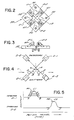
- a detector assembly generally designated 50, suitable for use in the first embodiment.
- the detector assembly 50 comprises a planar square housing or frame 52 having mounting holes 54 in the corners for securing the detector assembly 50 in position on the plotter.
- a pair of photo-emitters, identified as E-1 and E-2, and a pair of corresponding associated photo-detectors, indentified as D-1 and D-2, are secured to the frame 52 by screws 60 so that the photo beams 56 and 58 passing from the emitters E-1 and E-2 to the detectors D-1 and D-2, respectively, intersect.
- Beam 56 forms the angle ⁇ with the X axis
- the beam 58 forms the angle ⁇ with the X axis, the angles being illustrated as 45°.
- the frame 52 has a clear area intermediate the associated emitters and detectors through which the pen tip can travel and intersect the beams 56, 58 of light. Each detector produces an electrical signal indicative of the interruption of its associated beam, caused by a movement of the pen tip through the beam, and is connected to external logic and memory circuitry through wires 62.
- movement of the pen tip (indicated by circles) in the direction of the arrow 59 causes the pen tip to begin contact at point A with the beam 56 passing from emitter E-1 to detector D-1, eventually block off the beam 56, and finally terminate contact at point B with the bem 56, thereby to allow resumption of the beam passing to detector D-1.
- further movement of the pen tip in the direction of the arrow 59 causes the pen tip to begin at point C to intercept the beam 58 passing from emitter E-2 to detector D-2, eventually to interrupt the beam 58 completely, and finally at point D to permit resumption of the beam 58 passing to detector D-2.
- the tip of the new pen is passed through the open area of the detector assembly 50. This causes the pen tip first to interrupt either beam 56 or beam 58. If the pen tip interrupts beam 56 first, the pen tip is below the center point (that is, the intersection point of the beams 56, 58); if the pen tip interrupts beam 58 first, the pen tip is above the center point. If the pen tip interrupts both beams 56, 58 simultaneously, the pen tip is directly at the center point. As illustrated in FIG. 4, the pen tip is below the center point and interrupts first beam 56 and then beam 58.
- the pen tip moves through the detector assembly at a constant rate such that the detector output signal amplitude may be considered a function of either time or pen tip travel.
- the determination of the time of occurrence of a signal is also a determination of pen-tip travel along an axis.
- it is a functional equivalent to take data points at predetermined pen-tip travel points, with output signal amplitude being directly related to pen-tip travel distances, without regard to time.
- Points A and B can be determined as a minimum or threshold deflection of the output of detector D-1 from its baseline or non-interrupted level (representing an interruption of beam 56), and points C and D can be determined as a minimum or threshold deviation of the output of detector D-2 from its baseline or non-interrupted level (representing an interruption of beam 58).
- the time of the signal from detector D-1 can then be interpreted as the average of the times for points A and B, while the time of the signal from detector D-2 can then be interpreted as the average of the time for points C and D.
- the maximum point M1 of the curve between points A and B can be taken as the time of the signal of detector D-1
- the maximum point M2 of the curve between points C and D can be taken as the time of the signal of detector D-2. While both of these techniques are theoretically workable, in practice they have not proven to be entirely reliable.
- a single transient noise or glitch may so affect the one or two electrical signals being relied upon that greatly erroneous signal times are determined according to these techniques. Accordingly, it is preferred to utilize the averaging technique described below which relies on a number of different data points taken at different signal strengths so that an error in any small number of data points does not markedly affect the overall result.
- the search continues inwardly within the array from points M and N for the first data points where the output is at least equal to the incremented threshold. Once these points, indicated in FIG. 5 as P and Q, are determined, the two times thereof are averaged to provide a second averaged time A2. The threshold is then incremented by the threshold increment I t , and this procedure is repeated L times (for points R, S, etc.) to determine the averaged times A i for L different threshold values T. (Only three pairs of data points, rather than L pairs are illustrated in FIG. 5 in order to preserve clarity of illustration).
- the centerline C1 for the first signal and the centerline C2 for the second signal each equal to the average A of all of the averaged times of the signal, is determined by summing up all of the averaged times (A i through A L ) and dividing by L according to the formula: Assuming that the signal produced a perfect bell-shaped curve, with no noises or glitches being present, the centerline time obtained by this technique would be equal to that obtained by averaging data points A and B (or C and D) or determining a maximum point M1 or (M2). On the other hand, the centerline value obtained by this technique will remain relatively constant despite the presence of a few erroneous data points such as might result from noise or glitches.
- highest and lowest averaged times may be excluded before averaging the remaining averaged times.
- any given averaged time which is not within a given percentage of the average averaged time may be excluded and the average averaged time redetermined based on the remaining averaged times.
- the axial position of the pen tip along the X axis is functionally related to both the order in which the first and second signals occur (as this is functionally related to whether beam 56 or 58 is first interrupted and hence whether the pen tip is above or below the point of intersection of the beams 56, 58) and the difference in the times of occurrence of the first and second signals (as this is functionally related to how far above or below the point of intersection the pen tip is disposed).
- the axial position of the pen tip along the Y axis is functionally related to both the geometry of the detector assembly and the sum (more particularly, the average) of the times of occurrence of the first and second signals.
- the detector assembly 50 is shown as having the beams 56 and 58 form with the X axis angles ⁇ and ⁇ respectively, with these respective angles each being equal and 45 degrees.
- the principles of the present invention are, however, equally applicable to variations of the first embodiment wherein the angles are not equal or are not 45 degrees. However in this instance more sophisticated calculations must be performed to compensate for the variance in angle.
- the position of the current pen can be corrected to the position of the prior pen by moving the pen carriage, the media or both by a total of dx along the X axis and a total of dy along the Y axis.
- the correction factors dx and dy may be determined as axial positions of the current pen relative to the detector assembly.
- the axial position of the pen along the X axis is functionally related both to the order in which the first and second signals occur and the difference in the times of occurrence of the first and second signals.
- the axial position of the pen along the X axis is functionally related to the geometry of the detector assembly (that is, the angles ⁇ and ⁇ ) and the average of the times of occurrence C1, C2 of the first and second signals.
- a second embodiment of the present invention utilizes a single beam of radiation with a single photo-detector.
- a detector assembly generally designated 70, suitable for use in the second embodiment.
- the detector assembly 70 comprises a housing or frame 72 having mounting holes 74 for securing the detector assembly 70 in position on the plotter.
- a photo-emitter, identified as E, and associated photo-detector, identified as D, are secured to one side of the frame 72 with a reflecting mirror 76 being disposed on the other side of the frame so that a beam 78 emitted by the emitter E is reflected by the mirror 76 into the detector D.
- the frame 72 has an open area, intermediate the emitter E and detector D on one side and the mirror 76 on the other side, through which the pen tip can travel and intersect the beam 78 of light.
- the angle of the various components (emitter E, mirror 76 and detector D) in the housing 70 enables a beam 78 of light from the emitter E to cross the open area in the housing, reflect off the mirror 76, again cross the open area and be received by the detector D.
- the open area in the housing 70 allows a moving pen tip to intersect the same beam of light twice.
- the detector D is connected to external logic and memory circuitry through appropriate wiring (not shown) and produces a signal indicative of the interruption of the beam 78 caused by a movement of the pen tip through the beam. Interruption of the beam pre-reflection causes a first signal, and interruption of the beam post-reflection causes a second signal.
- the included angle between the pre-reflection and post-reflection beam is 2d as shown in FIG. 7.
- movement of the pen tip (indicated by circles) in the direction of the arrow 80 causes the pen tip to begin contact at point A with the beam 78 passing from the emitter E to the mirror 76, eventually to block off the beam 78, and finally terminate contact at point B with the beam 78, to allow resumption of the beam passing to mirror 76.
- further movement of the pen tip in the direction of the arrow 80 causes the pen tip to begin at point C to intercept the beam 78 passing from the mirror 76 to the detector D, eventually to interrupt the beam 78 completely a second time, and finally at point D to permit resumption of the beam 78 passing from the mirror 76 to the detector D.
- first and second signals In order to determine the times of the first and second signals, a procedure similar to that utilized in the first embodiment is employed. Initially, however, some distinction must be made between the first signal represented roughly at its outer limits by points A and B and the second signal represented roughly at its outer limits by the points C and D. While this could be performed with mathematical rigor, it suffices for the purposes of the present invention to determine point A representing the beginning of the first signal (the leftmost part thereof as shown in FIG. 8) and to determine the point D representing the end of the second signal (the rightmost portion thereof as shown in FIG. 8), and then to consider as the dividing line or split 82 between the first and second signals the average of the times of points A and D. Thereafter in calculating the time of the first signal only the data points in the array prior to the time of the split 82 are considered, and in calculating the time of the second signal only the data points in the array subsequent to the time of the split 82 are considered.
- the axial position of the pen tip along the X axis is functionally related both to the geometry of the detector assembly 50 and the difference in the times of occurrence of the first and second signals -- that is, the differences between C1 and C2 in FIG. 8. The closer these times are together the closer the pen tip is to the side of the frame 72 containing the mirror 76, and the farther these times are apart the closer the pen tip is to the side of the frame 72 containing the emitter E and detector D.
- the axial position of the pen along the Y axis is functionaloally related to the sum of the times of the first and second signals -- that is, the sum (more particularly the average) of C1 and C2 in FIG. 8.
- a third embodiment of the present invention utilizes a pair of electromechanical sensors with strain gauges.
- a detector assembly generally designated 90, suitable for use in the third embodiment.
- the detector assembly 90 comprises a base block 92 having mounting holes 94 for securing the detector assembly 90 in position on the plotter.
- a pair of spring sensors S-1 and S-2 are attached at one end to opposite sides of the base block 92 at offset positions, the base block 92 itself serving as a spacer between the two sensor springs S-1, S-2.
- Each sensor spring includes a semicircular contact 96 at the free end thereof and an associated resistive strain gauge 98 near its center.
- each sensor spring produces an electrical signal indicative of deflection of the associated spring sensor contact 96, caused by a movement of the pen tip through the volume initially occupied by the associated contact 96, and is functionally connected to external logic and memory circuitry through wires (not shown).
- the spring sensors S1, S2 are disposed on the block 92 in such close juxtaposition that movement of the pen tip along the Y axis will, in all reasonably anticipatable instances, cause some deflection of both contacts 96. While there are obviously clear advantages to the use of semicircular contacts 96, contacts of other design and shape may be utilized instead.
- the elaborate averaging procedure preferably utilized to determine signal occurrence times or centerlines in connection with the first and second embodiments using light beams is not as important in connection with the third embodiment, although it is still preferred.
- the third embodiment will be described in connection with a simpler procedure.
- the centerlines and maximum strain gauge output amplitudes may be determined by the same and analogous averaging procedures, respectively.
- the axial position of the pen tip along the Y axis is functionally related to the sum (or more particularly, the average) of the positions represented by the points B and D, the points E and G, or, for greater accuracy, the points B, D, E, and G -- that is, the centerlines C1, C2 and C1 and C2 of the deflection(s).
- the axial position of the pen tip along the X axis is functionally related to the sum (or more particularly the average) of the strain gauge output amplitudes, M1 for the maximum amplitude of rear sensor S-1, and M2 for the maximum amplitude of the front sensor S-2.
- the value M2 may be either signed or absolute. (Where the signed values of the strain gauge outputs M1 and M2 are added together, the sum is functionally related to the width of the pen tip in the X axis.)
- a fourth embodiment of the present invention utilizes a single electromechanical spring sensor with a strain guage.
- a detector assembly generally designated 110, suitable for use in the fourth embodiment.
- the detector assembly 110 comprises a mounting block 112 having mounting holes 114 for securing the detector assembly 110 in position on the plotter.
- a single spring sensor, identified as S, is secured to the holder 112.
- the sensor S has a trapezoidal contact 116 at the free end thereof and an associated strain gauge 118 near its center.
- the strain gauge 118 produces an electrical signal indicative of deflection of the sensor contact 116 caused by a movement of the pen tip through the space normally occupied by the trapezoidal contact 116, and is functionally connected to external logic and memory circuitry through wires (not shown), As more clearly shown in FIG. 15, the trapezoidal contact 116 has its long side flush mounted on the arm of sensor S, with its non-parallel sides sloping inwardly at an angle. Its long side has a length 2d, and its height (between parallel sides) is h.
- the position X o of the current pen tip relative to the sensor along the X axis is functionally related to the signals produced by deflections arising out of engagement between the pen tip and the non-parallel sides of the contact 116
- the position Y o of the current pen tip relative to the sensor along the Y axis is functionally related to the signals produced by deflections arising out of engagement between the pen tip and the short side and non-parallel sides of the contact 116.
- X o and Y o are determined more particularly according to the following formulae: where y i are positions along the Y axis between points B and C; o i are strain gauge outputs between points B and C; y′ i are positions along the Y axis between points F and G; and o′ i are corresponding outputs between point F and G; y ⁇ i are positions along the Y axis between points D and E; n is the number of readings taken between points B and C, D and E, and F and G, the same number having been taken for all three surfaces; h is the height of the contact between parallel sides thereof; and ⁇ is the angle between the long side and the non-parallel sides of the contact.
- an initial pen is obtained by the pen carriage from the pen carousel. along a predetermined path calculated to cause the pen tip to pass through the operative part of the detector assembly 50, 70, 90, 110 (i.e., the light beams or contacts).
- the appropriate times, signal amplitudes and the like are then determined in order to characterize the initial pen.
- the first pen is then used, as intended, to create a plot. When the first pen is returned to the carousel and a new pen is obtained therefrom by the pen carriage, any previously applied corrections for the pen tip position are cancelled.
- the new pen is then moved through the operative part of the detector assembly, and, from the data thus collected, new values are obtained for the appropriate times, signal amplitudes and the like.
- the appropriate correction factors dx and dy are then calculated using the above-identified characteristics of the initial pen and the new pen, the appropriate equations and any required geometric constants for the detector assembly having previously been stored in memory.
- the correction factors dx and dy are then applied to the new pen and medium movements as the new pen is used to plot. Eventually the new pen is returned to the carousel, and the next pen is obtained and moved through the detector assembly, repeating the cycle. It will be appreciated that, preferably, the correction factor to be applied to the current pen is at all times relative to the initial pen rather than the immediate prior pen (except where the immediately prior pen happens to be the initial pen).
- the determination of an "axial position” is functionally equivalent to, encompasses, and is satisfied by a determination of the "characteristics of the axial position" -- in other words, a determination of the centerlines for the first and second embodiments and the centerlines and signal amplitude maxima for the third embodiment.
- the formulas for determing dx and dy for the first, second and third embodiments may be rearranged into X o and Y o axial positions for the current pen and an X o ′ and Y o ′ position for the prior pen, much as in the manner of the equations dx and dy for the fourth embodiment.
- the equation dx for the first embodiment may be rearranged as follows: Thus, in every calculation of dx or dy, there is an implicit calculation of the axial positions X o or Y o .
- the present invention provides an apparatus and method, for use in conjunction with a digital plotter incorporating controlled multiple marking devices to create displays on a medium, for determining the axial position of the marking devices along axes of movement and for detecting and compensating for variations in the axial position of a current marking device along one axis relative to the axial position of a prior marking device along the same axis.
- the present invention accomplishes the same using apparatus and method which functionally relate the position of the marking device to electrical signals from either electro/mechanical or photoelectric sensors.
- the pen tip position is detected by the sensors, and a current pen tip is positioned relative to a prior pen tip by first determining the position of successive pen tips with the sensors and then correcting the position of the current pen tip by moving the carriage, the medium, or both.
Landscapes
- Engineering & Computer Science (AREA)
- Automation & Control Theory (AREA)
- Physics & Mathematics (AREA)
- General Physics & Mathematics (AREA)
Applications Claiming Priority (2)
| Application Number | Priority Date | Filing Date | Title |
|---|---|---|---|
| US131984 | 1987-12-11 | ||
| US07/131,984 US4888710A (en) | 1987-12-11 | 1987-12-11 | Pen tip position detector |
Publications (1)
| Publication Number | Publication Date |
|---|---|
| EP0320316A2 true EP0320316A2 (de) | 1989-06-14 |
Family
ID=22451889
Family Applications (1)
| Application Number | Title | Priority Date | Filing Date |
|---|---|---|---|
| EP88311759A Withdrawn EP0320316A2 (de) | 1987-12-11 | 1988-12-12 | Positionsdetektor für Schreibstifte |
Country Status (4)
| Country | Link |
|---|---|
| US (1) | US4888710A (de) |
| EP (1) | EP0320316A2 (de) |
| AU (1) | AU2927789A (de) |
| WO (1) | WO1989005492A1 (de) |
Cited By (2)
| Publication number | Priority date | Publication date | Assignee | Title |
|---|---|---|---|---|
| DE19541132A1 (de) * | 1995-10-27 | 1997-04-30 | Hartmann & Braun Ag | Anordnung zum Positionieren eines Schreibstiftes in einer Registriereinrichtung |
| DE19541130A1 (de) * | 1995-10-27 | 1997-04-30 | Hartmann & Braun Ag | Verfahren zum Positionieren eines Schreibstiftes in einer Registriereinrichtung |
Families Citing this family (10)
| Publication number | Priority date | Publication date | Assignee | Title |
|---|---|---|---|---|
| USD340066S (en) | 1991-01-22 | 1993-10-05 | Mutoh Industries Ltd. | Ink jet plotter |
| USD339374S (en) | 1991-05-28 | 1993-09-14 | Calcomp Inc. | Pedestal-mounted case for a pen plotter |
| US5276970A (en) * | 1991-10-30 | 1994-01-11 | Hewlett-Packard Company | Codestrip in a large-format image-related device |
| US5329303A (en) * | 1991-12-05 | 1994-07-12 | Transit Services, Inc. | Compact chart recorder |
| US5408591A (en) * | 1992-06-01 | 1995-04-18 | Calcomp Inc. | Automatic calibration and servo control scheme for offsetting mechanical and electronic component variances |
| US5341689A (en) * | 1993-04-30 | 1994-08-30 | Calcomp Inc. | Pen force gage for a pen plotter |
| US20060284952A1 (en) * | 2005-06-20 | 2006-12-21 | Jin-Sheng Lai | Positioning device for a large ink-jet printer |
| US20110174788A1 (en) * | 2010-01-21 | 2011-07-21 | Great Computer Corporation | Laser engraver with scanning function |
| JP1619851S (de) * | 2018-05-09 | 2018-12-10 | ||
| JP7505460B2 (ja) * | 2021-07-20 | 2024-06-25 | 横河電機株式会社 | 検出装置及び検出方法 |
Family Cites Families (9)
| Publication number | Priority date | Publication date | Assignee | Title |
|---|---|---|---|---|
| US3555254A (en) * | 1967-04-17 | 1971-01-12 | Gerber Scientific Instr Co | Error correcting system and method for use with plotters, machine tools and the like |
| US3686681A (en) * | 1970-04-20 | 1972-08-22 | Milgo Corp | Pen actuating mechanism for graphical display plotter |
| JPS55159985A (en) * | 1979-05-31 | 1980-12-12 | Canon Inc | Recording device |
| US4567565A (en) * | 1981-11-03 | 1986-01-28 | Hewlett-Packard Company | Apparatus and method for pen-lift system |
| US4573129A (en) * | 1982-02-25 | 1986-02-25 | Hewlett-Packard Company | Automatic pen-sensor |
| JPS58192188A (ja) * | 1982-05-06 | 1983-11-09 | Alps Electric Co Ltd | ペン式記録装置の駆動方法 |
| US4677572A (en) * | 1984-07-23 | 1987-06-30 | Sanders Associates, Inc. | Pen turret control system |
| JPS61228996A (ja) * | 1985-04-03 | 1986-10-13 | 岩崎通信機株式会社 | ペン制御回路 |
| US4630483A (en) * | 1985-07-24 | 1986-12-23 | Engdahl Paul D | Peak accelerograph |
-
1987
- 1987-12-11 US US07/131,984 patent/US4888710A/en not_active Expired - Fee Related
-
1988
- 1988-12-12 WO PCT/US1988/004368 patent/WO1989005492A1/en not_active Ceased
- 1988-12-12 EP EP88311759A patent/EP0320316A2/de not_active Withdrawn
- 1988-12-12 AU AU29277/89A patent/AU2927789A/en not_active Abandoned
Cited By (4)
| Publication number | Priority date | Publication date | Assignee | Title |
|---|---|---|---|---|
| DE19541132A1 (de) * | 1995-10-27 | 1997-04-30 | Hartmann & Braun Ag | Anordnung zum Positionieren eines Schreibstiftes in einer Registriereinrichtung |
| DE19541130A1 (de) * | 1995-10-27 | 1997-04-30 | Hartmann & Braun Ag | Verfahren zum Positionieren eines Schreibstiftes in einer Registriereinrichtung |
| US5764244A (en) * | 1995-10-27 | 1998-06-09 | Hartmann & Braun A.G. | Arrangement for positioning a pen in a recording device |
| US5764016A (en) * | 1995-10-27 | 1998-06-09 | Hartmann & Braun Ag | Method for positioning a pen in a recording device |
Also Published As
| Publication number | Publication date |
|---|---|
| US4888710A (en) | 1989-12-19 |
| AU2927789A (en) | 1989-07-05 |
| WO1989005492A1 (en) | 1989-06-15 |
Similar Documents
| Publication | Publication Date | Title |
|---|---|---|
| US4888710A (en) | Pen tip position detector | |
| EP1039262B1 (de) | Verfahren und Apparat zur Blattdicken- und Schwellungsmessung | |
| EP1766325B1 (de) | Messungssonde zur verwendung in koordinatenmessmaschinen | |
| US4932131A (en) | Position determination apparatus | |
| US8144340B2 (en) | Surface sensing device with optical sensor | |
| EP3401635A1 (de) | Sonde für berührungsauslösung | |
| WO1990000717A1 (en) | Probes | |
| GB2311862A (en) | Profile measuring apparatus | |
| JPH0310042B2 (de) | ||
| US4892407A (en) | Optical measuring apparatus for use on machines | |
| JPH07324948A (ja) | 位置測定装置 | |
| JP2997412B2 (ja) | 多座標走査ヘッド | |
| US4435674A (en) | Method and apparatus for generating a verified plot | |
| US7117110B2 (en) | Measuring method and measuring apparatus | |
| EP0599807B1 (de) | Positionsdetektor | |
| US4573129A (en) | Automatic pen-sensor | |
| EP0183951A2 (de) | Gerät zur Bestimmung der Koordinatenlage eines manuell beweglichen Gegenstandes auf einer Oberfläche | |
| CN114459388B (zh) | 一种单激光双psd深孔直线度检测装置及方法 | |
| US4689892A (en) | Apparatus and method of measuring surface heights | |
| US4748748A (en) | Method and apparatus for measuring height variations on a floor surface | |
| JP6696784B2 (ja) | カード状媒体計数機構およびカード状媒体収容装置 | |
| JPS60213810A (ja) | 位置感知装置 | |
| US3251135A (en) | Apparatus for measuring or indicating lack of straightness of a surface | |
| SE502409C2 (sv) | Mätanordning för dimensionsmätning av ett stort mätobjekt, t.e.x chassiet hos en bil | |
| CN115183676B (zh) | 移动物体直线导航用调姿传感器 |
Legal Events
| Date | Code | Title | Description |
|---|---|---|---|
| PUAI | Public reference made under article 153(3) epc to a published international application that has entered the european phase |
Free format text: ORIGINAL CODE: 0009012 |
|
| AK | Designated contracting states |
Kind code of ref document: A2 Designated state(s): AT BE CH DE ES FR GB GR IT LI LU NL SE |
|
| STAA | Information on the status of an ep patent application or granted ep patent |
Free format text: STATUS: THE APPLICATION IS DEEMED TO BE WITHDRAWN |
|
| 18D | Application deemed to be withdrawn |
Effective date: 19920703 |