EP0320252B1 - Rotary electrical machines - Google Patents
Rotary electrical machines Download PDFInfo
- Publication number
- EP0320252B1 EP0320252B1 EP88311615A EP88311615A EP0320252B1 EP 0320252 B1 EP0320252 B1 EP 0320252B1 EP 88311615 A EP88311615 A EP 88311615A EP 88311615 A EP88311615 A EP 88311615A EP 0320252 B1 EP0320252 B1 EP 0320252B1
- Authority
- EP
- European Patent Office
- Prior art keywords
- core
- machine according
- stator
- laminations
- support structure
- Prior art date
- Legal status (The legal status is an assumption and is not a legal conclusion. Google has not performed a legal analysis and makes no representation as to the accuracy of the status listed.)
- Expired - Lifetime
Links
- 238000004804 winding Methods 0.000 claims description 33
- 238000003475 lamination Methods 0.000 claims description 32
- 235000015895 biscuits Nutrition 0.000 claims description 9
- 230000006835 compression Effects 0.000 claims description 3
- 238000007906 compression Methods 0.000 claims description 3
- 239000004020 conductor Substances 0.000 claims description 2
- 230000000452 restraining effect Effects 0.000 claims 1
- 238000010276 construction Methods 0.000 description 5
- 239000002783 friction material Substances 0.000 description 5
- 238000004873 anchoring Methods 0.000 description 3
- 239000002826 coolant Substances 0.000 description 3
- 238000013016 damping Methods 0.000 description 2
- 239000012530 fluid Substances 0.000 description 2
- 239000000463 material Substances 0.000 description 2
- RYGMFSIKBFXOCR-UHFFFAOYSA-N Copper Chemical compound [Cu] RYGMFSIKBFXOCR-UHFFFAOYSA-N 0.000 description 1
- 229910000831 Steel Inorganic materials 0.000 description 1
- 230000015572 biosynthetic process Effects 0.000 description 1
- 229910052802 copper Inorganic materials 0.000 description 1
- 239000010949 copper Substances 0.000 description 1
- 238000006073 displacement reaction Methods 0.000 description 1
- 230000000694 effects Effects 0.000 description 1
- 230000005284 excitation Effects 0.000 description 1
- 238000003780 insertion Methods 0.000 description 1
- 230000037431 insertion Effects 0.000 description 1
- 238000009434 installation Methods 0.000 description 1
- 238000004519 manufacturing process Methods 0.000 description 1
- 239000000203 mixture Substances 0.000 description 1
- 230000002093 peripheral effect Effects 0.000 description 1
- -1 polytetrafluoroethylene Polymers 0.000 description 1
- 229920001343 polytetrafluoroethylene Polymers 0.000 description 1
- 239000004810 polytetrafluoroethylene Substances 0.000 description 1
- 230000000284 resting effect Effects 0.000 description 1
- 239000010959 steel Substances 0.000 description 1
- 238000003466 welding Methods 0.000 description 1
Images

Classifications
-
- H—ELECTRICITY
- H02—GENERATION; CONVERSION OR DISTRIBUTION OF ELECTRIC POWER
- H02K—DYNAMO-ELECTRIC MACHINES
- H02K1/00—Details of the magnetic circuit
- H02K1/06—Details of the magnetic circuit characterised by the shape, form or construction
- H02K1/12—Stationary parts of the magnetic circuit
- H02K1/18—Means for mounting or fastening magnetic stationary parts on to, or to, the stator structures
- H02K1/185—Means for mounting or fastening magnetic stationary parts on to, or to, the stator structures to outer stators
-
- H—ELECTRICITY
- H02—GENERATION; CONVERSION OR DISTRIBUTION OF ELECTRIC POWER
- H02K—DYNAMO-ELECTRIC MACHINES
- H02K15/00—Methods or apparatus specially adapted for manufacturing, assembling, maintaining or repairing of dynamo-electric machines
- H02K15/02—Methods or apparatus specially adapted for manufacturing, assembling, maintaining or repairing of dynamo-electric machines of stator or rotor bodies
- H02K15/024—Methods or apparatus specially adapted for manufacturing, assembling, maintaining or repairing of dynamo-electric machines of stator or rotor bodies with slots
- H02K15/028—Methods or apparatus specially adapted for manufacturing, assembling, maintaining or repairing of dynamo-electric machines of stator or rotor bodies with slots for fastening to casing or support, respectively to shaft or hub
-
- H—ELECTRICITY
- H02—GENERATION; CONVERSION OR DISTRIBUTION OF ELECTRIC POWER
- H02K—DYNAMO-ELECTRIC MACHINES
- H02K3/00—Details of windings
- H02K3/46—Fastening of windings on the stator or rotor structure
- H02K3/50—Fastening of winding heads, equalising connectors, or connections thereto
- H02K3/505—Fastening of winding heads, equalising connectors, or connections thereto for large machine windings, e.g. bar windings
-
- Y—GENERAL TAGGING OF NEW TECHNOLOGICAL DEVELOPMENTS; GENERAL TAGGING OF CROSS-SECTIONAL TECHNOLOGIES SPANNING OVER SEVERAL SECTIONS OF THE IPC; TECHNICAL SUBJECTS COVERED BY FORMER USPC CROSS-REFERENCE ART COLLECTIONS [XRACs] AND DIGESTS
- Y10—TECHNICAL SUBJECTS COVERED BY FORMER USPC
- Y10T—TECHNICAL SUBJECTS COVERED BY FORMER US CLASSIFICATION
- Y10T29/00—Metal working
- Y10T29/49—Method of mechanical manufacture
- Y10T29/49002—Electrical device making
- Y10T29/49009—Dynamoelectric machine
Definitions
- This invention relates to large rotary electrical machines, eg. with ratings of 1MW and upwards, having a generally horizontal axis of rotation.
- rotary electrical machines for example generators of turbine-generator sets
- a stator construction comprising a generally annular outer casing which carries the stator core and the stator winding either directly or through an inner annular core frame (see "The Mechanical Design of Large Turbogenerators, B.A Marlow, Proc. Instn. Mech. Engrs., Vol. 200 (1986) No. 135).
- outer casing or the core frame has struts extending radially inwards that provide support and location for the core laminations.
- Heavy end plates sometimes secured together by through bolts, hold the laminations together under a relatively high compressive force in order to limit axial thermal expansion and vibration.
- the outer casing or the core frame is first constructed and is fitted with one end plate. It is then stood with its axis vertical and the end plate lowermost so that the laminations, usually in segmental form, can be dropped individually into the frame and fitted into place. The other end plate can then be added and the core laminations clamped, after which the core frame is returned to a horizontal position for the remaining assembly operations, including fitting the windings.
- the construction of the core frame and fitting the core laminations into it which typically can take 16-20 weeks for a 500MW generator, adds significantly to the costs of manufacture as well as requiring significant capital investment for plant capable of handling the core frame during the various operations.
- a rotary electrical machine comprising an open topped support structure containing a stator having an annular core comprising laminations held under compression between end plates and mounted on supports within said structure, a rotor extending through the core and mounted for rotation about a horizontal axis, the interior of said structure being accessible from above wherein the open top of said support structure is provided for the assembly of the core, said supports of the structure extending along the length of the core laminations to engage with downwardly directed faces of the core laminations on opposite sides of a vertical plane through said axis, whereby the stator core can be assembled on the support structure by lowering the laminations and/or biscuits thereof onto said supports with the structure horizontal.
- the assembly space can be arranged to be accessible both from the sides and from above, simplifying the task of bringing the laminations into position.
- the stator supports are conveniently disposed below the axis of rotation to cooperate with downwardly directed faces of the stator core that are part of a regular polygonal or circular cross-section of the core.
- the support structure of the present invention allows the core to be mounted in a manner that avoids this problem, by arranging that the core is axially engaged with the support structure at a location along its length and is otherwise free to move axially relative thereto, whereby relative thermal movement between the core and the structure can occur relatively freely.
- FIG. 1 illustrates a generator 10 having a support structure 12, an annular stator core 14 supported on the structure, a rotor 16 extending through the core and mounted on bearings (not shown) for rotation about a end winding supports on the ends of the tension elements and the second group of clamping elements securing the core laminations between and spaced from said end winding supports, said second group applying said axial clamping pressure to the core laminations, and spring means being provided on the tension elements to permit relative axial movement between said first and second groups of clamping elements at least at one end of the stator.
- This arrangement for permitting thermal movements between the windings and the core in the axial direction can also be employed in otherwise conventional rotary electrical machines, ie. independently of whether there is provision for relative thermal movement between the core and its support structure.
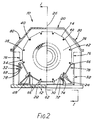
- FIG. 1 illustrates a generator 10 having a support structure 12, an annular stator core 14 supported on the structure, a rotor 16 extending through the core and mounted on bearings (not shown) for rotation about a horizontal axis 18, and a fluid-tight housing 20 encasing the stator and rotor.
- the support structure 12 comprises a base member 22 upon which there are fixed upstands in the form of two support beams 24, one located on each side of the central axial plane 26 of the generator and running parallel to the rotary axis to extend along the full length of the core 14.
- the core has a regular polygonal cross-section and rests through two downwardly directed faces of that cross-section on top webs 28 of the beams 24 and is separated from them by low-friction material 30, such as polytetrafluoroethylene.
- Two axially spaced core support cradles 32 are also mounted on the base member 22.
- the cradles 32 each have a profile facing the core 14 which is shaped to conform generally to the opposed peripheral region of the core 14, but preferably there is normally a small clearance between them and the core.
- the core 14 comprises two end plates 34,36 between which are clamped a plurality of biscuits 38 (not shown individually) of pre-assembled core laminations.
- the clamping pressure is applied by tie bolts 40 extending axially through recesses 42 in the periphery of the laminated body of the core and apertures in the end plates, nuts 44 being threaded on the bolts at both ends of the core.
- Springs 46 are mounted between the nuts and one end plate 36 to accommodate differential thermal movement between the bolts and the laminated core axially of the core. Restraint of this relative movement is minimised by ensuring that there are adequate radial clearances for the bolts and by using low friction material where required on sliding surfaces.
- the tie bolts 40 extend beyond both ends of the stator core, their terminal portions being employed to mount frusto-conical end winding supports 54,56 which are secured at a spacing from the end plates 34,36 by further nuts 44 on the ends of the bolts 40.
- the stator windings 58 held in slots in the core, extend from the ends of the core and their end windings are secured on the supports 54,56 by clamps 60.
- the materials of the windings 58 and of the bolts 40 can be so chosen that it is not necessary to design for relative thermal movement between them.
- windings of copper have a coefficient of expansion of 17x10 ⁇ 6 /°C, with which can be employed bolts of austenitic steel which has a coefficient of 18x10 ⁇ 6/°C.
- Both end plates 34,36 of the core have lower extensions 34a,36a respectively, that are a free sliding fit between the beams 24.
- the sides of the extensions are preferably vertical or taper downwardly so that the end plates can be lowered into place.
- One end plate 34 of the core is axially fixed on the support structure 12.
- the end plate has an integral key formation 62 which engages a slot 64 in the base member 22.
- the end plate is firmly anchored to the beams 24, for example by bolted brackets (not shown) or welding.
- the remainder of the core is free to expand and contract axially on the beams 24 under the influence of thermal effects.
- the low-friction material 30 is preferably fixed to the core face so that it slides with the core, thereby preventing damage to the edges of the laminations. Such movement relative to the tie bolts is possible because of the provision of the springs 46. Relative axial movement is also possible between the stator windings and the core, the windings being located by the end winding supports substantially independently of axial movements of the core itself. It is preferably at the end winding support 54, adjacent the fixed end plate 34, that the stator end windings extend to connectors (not shown) for connection to external conductors (not shown) in known manner. With these measures, although biscuits are used to build up the core, with a consequent high thermal expansion rate of the main body of the core, the axial forces imposed on the windings remain minimal.
- the mass of the stator core may be sufficient to allow it to rest stably on the supporting slides, uninfluenced by torques arising from the electromagnetic forces imposed during operation. Similarly lifting of the free end of the core, remote from the end plate is resisted by the core mass.
- the polygonal cross-section of the core and the conforming profile of the support structure facing it, in particular the cradles 32, can of course resist any tendency of the core to turn on its axis. Local resistance against rotation and lifting can be offered by the extensions 34a,36a of the end plates.
- keying means which give a positive restraint along the length of the core against such displacements.
- axial keys 66 which extend between keyways 68 in the cradles 32 and the adjoining recesses 42 in the biscuits, these recesses extending into the end plates 34,36.
- the axially displaceable end plate 36 has a pair of wedge-shaped keyways 72 which engage dovetail key blocks 74 secured to the facing side surfaces of the beams 24 so that the end plate 36 serves to guide the axial movements of the core.
- the outer peripheries of the end winding supports 54,56 can also engage the beams 24 slidably, and possibly be supported by the beams. This, and also the mounting of the end winding supports at a spacing from the stator core helps to isolate the windings 58 from axial movements of the core 14 and assisting in the control of vibration.
- the support 54 can additionally or alternatively be in contact with the end plate 34.
- the stator can be assembled on the support structure 12 by lowering the end plates 34,36 and the core biscuits 38 into position on the horizontal support beams 24, this being facilitated by the fact that there is open access on both sides of the structure 12 as well as from above, and the assembled elements of the core are clamped together by the tie bolts 40. It is also possible to assemble individual annular laminations on the support structure to build up the core, although that would take longer.
- the stator winding end rings 54,56 can then be secured on the ends of the through bolts, the windings 58 inserted in their slots in the assembled core, and the ends of the windings secured to the end rings and electrically coupled to the core windings.
- coolant circulation means may be put in place before or after the building of the core, as convenient.
- the core laminations will of course have further aligned slots, holes etc., in the conventional manner, for such purposes as the flow of coolant fluid.
- Coolers for the circulating coolant fluid can be located in any convenient place, for example, within the housing alongside the core and between the cradles, and between the central cradle 32 and the end plate 34 as shown in ghost outline at 76 in Fig. 2.
- insertions (not shown) of rubber or other suitable damping material can be put at appropriate locations, eg. between the core and the low friction material 30 and also between the fixed end plate 34 and the main body of the stator core.
- anti-vibration devices known per se, can be connected between the core and the base member 22. It may be preferred, in order to isolate the housing and rotor bearings as far as possible from the stator vibrations, to mount the housing 20 and the rotor bearings directly onto the foundations (not shown) on which the base member 22 will rest.
- the housing 20 is mounted on the base member 22 together with the rotor bearings (not shown) that lie beyond the ends of the stator. Consequently, it is possible to move the generator as a self-contained unit.
- the cradles 32 have attachment points 78 for a lift harness, the points 78 being accessible via housing apertures normally closed by plates 80. It will be appreciated that the generator, when suspended from these points, derives considerable stiffness from the assembled core; this illustrates a further unique feature of the construction in that the core functions as a significant structural member.
- the illustrated construction can be modified in many ways within the scope of the invention.
- the tie bolts 40 are shown running in open slots in the periphery of the main body of the core, but they can be arranged on a pitch circle greater than the outside diameter of the core 14, the end rings 34,36 and the end winding supports 54,46 being furnished with apertured radial lugs to receive the bolts.
- the bolts can also be located on pitch circles of different diameters.
- the anchoring of the core 14 relative to the support structure 12 need not be at an end of the core. By anchoring the core elsewhere, eg. in the middle of its length, both ends can be left free to move axially.
- the anchoring of the core can be achieved in a number of ways.
- a key can engage respective keyways formed in the base member 22 and the outer periphery of the core laminations intermediate the length of the core, a third cradle 32 being provided to support the end of the core.
- a key can be formed integrally with the third cradle 32 adjacent that end of the core, the key engaging a keyway in the outer periphery of the core laminations.
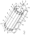
- the support beams 24 are shown in Fig. 3 extending beyond the core, to support, for example, the generator exciter and the rotor bearings. However, it is also possible to dispense with the beams 24.
- the core is mounted on bearing blocks resting on slideways carried by the cradles 32, the slideways being lubricated or faced with low-friction material.
- the cradles 32 are fixed relative to the core and are themselves slidable in slideways.
- the core is mounted on relatively thin supports which can flex in the axial direction. Also, more closely analogous to the illustrated example, the core can be mounted on rollers to permit its axial expansion.
- the external cross-section shape of the core is not limited to the dodecahedron shown and may, for example, be circular.
Landscapes
- Engineering & Computer Science (AREA)
- Power Engineering (AREA)
- Manufacturing & Machinery (AREA)
- Iron Core Of Rotating Electric Machines (AREA)
- Insulation, Fastening Of Motor, Generator Windings (AREA)
- Motor Or Generator Frames (AREA)
Description
- This invention relates to large rotary electrical machines, eg. with ratings of 1MW and upwards, having a generally horizontal axis of rotation.
- Large rotary electrical machines, for example generators of turbine-generator sets, have a stator construction comprising a generally annular outer casing which carries the stator core and the stator winding either directly or through an inner annular core frame (see "The Mechanical Design of Large Turbogenerators, B.A Marlow, Proc. Instn. Mech. Engrs., Vol. 200 (1986) No. 135). In each case outer casing or the core frame has struts extending radially inwards that provide support and location for the core laminations. Heavy end plates, sometimes secured together by through bolts, hold the laminations together under a relatively high compressive force in order to limit axial thermal expansion and vibration.
- To assemble such cores, the outer casing or the core frame, as the case may be, is first constructed and is fitted with one end plate. It is then stood with its axis vertical and the end plate lowermost so that the laminations, usually in segmental form, can be dropped individually into the frame and fitted into place. The other end plate can then be added and the core laminations clamped, after which the core frame is returned to a horizontal position for the remaining assembly operations, including fitting the windings. The construction of the core frame and fitting the core laminations into it, which typically can take 16-20 weeks for a 500MW generator, adds significantly to the costs of manufacture as well as requiring significant capital investment for plant capable of handling the core frame during the various operations.
- According to the present invention, there is provided a rotary electrical machine comprising an open topped support structure containing a stator having an annular core comprising laminations held under compression between end plates and mounted on supports within said structure, a rotor extending through the core and mounted for rotation about a horizontal axis, the interior of said structure being accessible from above wherein the open top of said support structure is provided for the assembly of the core, said supports of the structure extending along the length of the core laminations to engage with downwardly directed faces of the core laminations on opposite sides of a vertical plane through said axis, whereby the stator core can be assembled on the support structure by lowering the laminations and/or biscuits thereof onto said supports with the structure horizontal.
- By employing such an arrangement a substantial reduction of assembly time can be achieved. The assembly space can be arranged to be accessible both from the sides and from above, simplifying the task of bringing the laminations into position. The stator supports are conveniently disposed below the axis of rotation to cooperate with downwardly directed faces of the stator core that are part of a regular polygonal or circular cross-section of the core.
- In US 3916233 a rotary electrical machine is disclosed in which a housing acting as a stator support has an open-topped structure into which an assembled stator can be lowered to simplify its installation and removal. This earlier proposal, however, provides no opportunity for the stator core to be assembled inside the structure.
- It is also known to reduce the time for assembly of a large stator core by producing pre-assembled toroidal packets of laminations which are commonly referred to as "biscuits". By this means it is no longer necessary to fit each lamination into the core frame individually so much time can be saved. A complication arises, however, in that differential expansion between the core and its frame can impose considerable stresses. Such expansion is relatively easily accommodated when the core is built up from individual laminations, because the inherent non-planarity of the laminations gives the core an enhanced flexibility, but biscuits, being composed of pre-compressed packets of laminations, have a much higher coefficient of thermal expansion and it may not be possible to substitute them directly for individual laminations. To limit expansion stresses, mixtures of biscuits and laminations may be used, but in a conventional stator construction that would reintroduce the disadvantages already mentioned.
- The support structure of the present invention, however, allows the core to be mounted in a manner that avoids this problem, by arranging that the core is axially engaged with the support structure at a location along its length and is otherwise free to move axially relative thereto, whereby relative thermal movement between the core and the structure can occur relatively freely.
- By way of example only, the invention will be described in more detail with reference to the accompanying diagrammatic drawings, in which:
- Figs. 1 and 2 are side and end views of a stator/rotor assembly of an electrical machine according to the invention, Fig. 1 being partly sectioned on the line I-I in Fig. 2 and Fig. 2 being partly sectioned on the line II-II in Fig. 1, and
- Fig. 3 is an isometric view illustrating schematically the support of the stator.
- The drawings illustrate a
generator 10 having asupport structure 12, anannular stator core 14 supported on the structure, arotor 16 extending through the core and mounted on bearings (not shown) for rotation about a end winding supports on the ends of the tension elements and the second group of clamping elements securing the core laminations between and spaced from said end winding supports, said second group applying said axial clamping pressure to the core laminations, and spring means being provided on the tension elements to permit relative axial movement between said first and second groups of clamping elements at least at one end of the stator. - This arrangement for permitting thermal movements between the windings and the core in the axial direction can also be employed in otherwise conventional rotary electrical machines, ie. independently of whether there is provision for relative thermal movement between the core and its support structure.
- By way of example only, the invention will be described in more detail with reference to the accompanying diagrammatic drawings, in which:
- Figs. 1 and 2 are side and end views of a stator/rotor assembly of an electrical machine according to the invention, Fig. 1 being partly sectioned on the line I-I in Fig. 2 and Fig. 2 being partly sectioned on the line II-II in Fig. 1, and
- Fig. 3 is an isometric view illustrating schematically the support of the stator.
- The drawings illustrate a
generator 10 having asupport structure 12, anannular stator core 14 supported on the structure, arotor 16 extending through the core and mounted on bearings (not shown) for rotation about ahorizontal axis 18, and a fluid-tight housing 20 encasing the stator and rotor. - The
support structure 12 comprises abase member 22 upon which there are fixed upstands in the form of twosupport beams 24, one located on each side of the centralaxial plane 26 of the generator and running parallel to the rotary axis to extend along the full length of thecore 14. The core has a regular polygonal cross-section and rests through two downwardly directed faces of that cross-section ontop webs 28 of thebeams 24 and is separated from them by low-friction material 30, such as polytetrafluoroethylene. Two axially spacedcore support cradles 32 are also mounted on thebase member 22. Thecradles 32 each have a profile facing thecore 14 which is shaped to conform generally to the opposed peripheral region of thecore 14, but preferably there is normally a small clearance between them and the core. - The
core 14 comprises twoend plates tie bolts 40 extending axially throughrecesses 42 in the periphery of the laminated body of the core and apertures in the end plates,nuts 44 being threaded on the bolts at both ends of the core.Springs 46 are mounted between the nuts and oneend plate 36 to accommodate differential thermal movement between the bolts and the laminated core axially of the core. Restraint of this relative movement is minimised by ensuring that there are adequate radial clearances for the bolts and by using low friction material where required on sliding surfaces. - The
tie bolts 40 extend beyond both ends of the stator core, their terminal portions being employed to mount frusto-conical end winding supports 54,56 which are secured at a spacing from theend plates further nuts 44 on the ends of thebolts 40. Thestator windings 58, held in slots in the core, extend from the ends of the core and their end windings are secured on thesupports clamps 60. The materials of thewindings 58 and of thebolts 40 can be so chosen that it is not necessary to design for relative thermal movement between them. For example, windings of copper have a coefficient of expansion of 17x10⁻⁶ /°C, with which can be employed bolts of austenitic steel which has a coefficient of 18x10⁻⁶/°C. - Both
end plates lower extensions 34a,36a respectively, that are a free sliding fit between thebeams 24. The sides of the extensions are preferably vertical or taper downwardly so that the end plates can be lowered into place. Oneend plate 34 of the core is axially fixed on thesupport structure 12. For this purpose, the end plate has anintegral key formation 62 which engages aslot 64 in thebase member 22. Additionally, the end plate is firmly anchored to thebeams 24, for example by bolted brackets (not shown) or welding. The remainder of the core is free to expand and contract axially on thebeams 24 under the influence of thermal effects. The low-friction material 30 is preferably fixed to the core face so that it slides with the core, thereby preventing damage to the edges of the laminations. Such movement relative to the tie bolts is possible because of the provision of thesprings 46. Relative axial movement is also possible between the stator windings and the core, the windings being located by the end winding supports substantially independently of axial movements of the core itself. It is preferably at theend winding support 54, adjacent the fixedend plate 34, that the stator end windings extend to connectors (not shown) for connection to external conductors (not shown) in known manner. With these measures, although biscuits are used to build up the core, with a consequent high thermal expansion rate of the main body of the core, the axial forces imposed on the windings remain minimal. - The mass of the stator core may be sufficient to allow it to rest stably on the supporting slides, uninfluenced by torques arising from the electromagnetic forces imposed during operation. Similarly lifting of the free end of the core, remote from the end plate is resisted by the core mass. The polygonal cross-section of the core and the conforming profile of the support structure facing it, in particular the
cradles 32, can of course resist any tendency of the core to turn on its axis. Local resistance against rotation and lifting can be offered by theextensions 34a,36a of the end plates. In addition, it is preferred, to provide keying means which give a positive restraint along the length of the core against such displacements. Illustrated areaxial keys 66 which extend betweenkeyways 68 in thecradles 32 and theadjoining recesses 42 in the biscuits, these recesses extending into theend plates displaceable end plate 36 has a pair of wedge-shaped keyways 72 which engage dovetailkey blocks 74 secured to the facing side surfaces of thebeams 24 so that theend plate 36 serves to guide the axial movements of the core. - The outer peripheries of the end winding supports 54,56 can also engage the
beams 24 slidably, and possibly be supported by the beams. This, and also the mounting of the end winding supports at a spacing from the stator core helps to isolate thewindings 58 from axial movements of thecore 14 and assisting in the control of vibration. Thesupport 54 can additionally or alternatively be in contact with theend plate 34. - The stator can be assembled on the
support structure 12 by lowering theend plates core biscuits 38 into position on the horizontal support beams 24, this being facilitated by the fact that there is open access on both sides of thestructure 12 as well as from above, and the assembled elements of the core are clamped together by thetie bolts 40. It is also possible to assemble individual annular laminations on the support structure to build up the core, although that would take longer. The stator winding end rings 54,56 can then be secured on the ends of the through bolts, thewindings 58 inserted in their slots in the assembled core, and the ends of the windings secured to the end rings and electrically coupled to the core windings. - Other components of the stator, such as coolant circulation means (not shown), may be put in place before or after the building of the core, as convenient. The core laminations will of course have further aligned slots, holes etc., in the conventional manner, for such purposes as the flow of coolant fluid. Coolers for the circulating coolant fluid can be located in any convenient place, for example, within the housing alongside the core and between the cradles, and between the
central cradle 32 and theend plate 34 as shown in ghost outline at 76 in Fig. 2. - For the damping of stator vibrations that occur in operation from the electromagnetic excitation of the stator by the rotor, insertions (not shown) of rubber or other suitable damping material can be put at appropriate locations, eg. between the core and the
low friction material 30 and also between thefixed end plate 34 and the main body of the stator core. In addition, anti-vibration devices, known per se, can be connected between the core and thebase member 22. It may be preferred, in order to isolate the housing and rotor bearings as far as possible from the stator vibrations, to mount thehousing 20 and the rotor bearings directly onto the foundations (not shown) on which thebase member 22 will rest. - In the illustrated example, the
housing 20 is mounted on thebase member 22 together with the rotor bearings (not shown) that lie beyond the ends of the stator. Consequently, it is possible to move the generator as a self-contained unit. To that end, thecradles 32 have attachment points 78 for a lift harness, thepoints 78 being accessible via housing apertures normally closed byplates 80. It will be appreciated that the generator, when suspended from these points, derives considerable stiffness from the assembled core; this illustrates a further unique feature of the construction in that the core functions as a significant structural member. - The illustrated construction can be modified in many ways within the scope of the invention. For example, the
tie bolts 40 are shown running in open slots in the periphery of the main body of the core, but they can be arranged on a pitch circle greater than the outside diameter of the core 14, the end rings 34,36 and theend winding supports - The anchoring of the core 14 relative to the
support structure 12 need not be at an end of the core. By anchoring the core elsewhere, eg. in the middle of its length, both ends can be left free to move axially. Furthermore, the anchoring of the core can be achieved in a number of ways. For example, a key can engage respective keyways formed in thebase member 22 and the outer periphery of the core laminations intermediate the length of the core, athird cradle 32 being provided to support the end of the core. Alternatively, a key can be formed integrally with thethird cradle 32 adjacent that end of the core, the key engaging a keyway in the outer periphery of the core laminations. - The support beams 24 are shown in Fig. 3 extending beyond the core, to support, for example, the generator exciter and the rotor bearings. However, it is also possible to dispense with the
beams 24. In one alternative the core is mounted on bearing blocks resting on slideways carried by thecradles 32, the slideways being lubricated or faced with low-friction material. As another possibility, thecradles 32 are fixed relative to the core and are themselves slidable in slideways. In a further alternative, the core is mounted on relatively thin supports which can flex in the axial direction. Also, more closely analogous to the illustrated example, the core can be mounted on rollers to permit its axial expansion. - The external cross-section shape of the core is not limited to the dodecahedron shown and may, for example, be circular.
- Although the foregoing description has been directed to a rotary electrical machine in the form of a generator, as will be appreciated by those skilled in the art the invention is equally applicable to motors and the term rotary electrical machine is to be construed accordingly.
Claims (14)
- A rotary electrical machine comprising an open-topped support structure (12) containing a stator having an annular core (14) comprising laminations held under compression between end plates (34,36) and mounted on supports (24) within said structure, a rotor (16) extending through the core and mounted for rotation about a horizontal axis, the interior of said structure being accessible from above, characterised in that the open top of said support structure (12) is provided for the assembly of the core, said supports (24) of the structure extending along the length of the core laminations to engage with downwardly directed faces of the core laminations on opposite sides of a vertical plane through said axis, whereby the stator core can be assembled on the structure by lowering the laminations and/or biscuits thereof onto said supports with the structure horizontal.
- A machine according to claim 1 wherein the end plates (34,36) are provided with elements (34a,36a,72) that cooperate with the support structure to resist torque and/or lift forces on the stator core.
- A machine according to claim 1 or claim 2 wherein the core (14) is axially engaged with the support structure (12) at a location along its length and is otherwise displaceable axially relative thereto, whereby relative thermal movements can take place freely between the core and the support structure in the axial direction.
- A machine according to claim 3 wherein said axial engagement is provided by the end plate (34) at one end of the core, by means of a keying projection (62) on the end plate engaging the support structure.
- A machine according to claim 3 or claim 4 wherein at least one axially extending key and keyway connection (66,68;72,74) is provided between the support structure (12) and the stator core (14) for rotational and/or torsional restraint of the core on said structure, said key and keyway connection being slidably engaged to permit relative axial movement between the core and said structure.
- A machine according to any one of the preceding claims wherein stator windings (58) are mounted in the core (14) by means permitting relative thermal movements between the windings and the core in the axial direction.
- A machine according to any one of claims 3 to 5 together with claim 6 wherein said axial engagement is provided at or adjacent an end of the core from which the core windings (58) extend for connection to external electrical conductors.
- A machine according to any one of the preceding claims wherein the support structure comprises respective beams (24) on opposite sides of a vertical plane through the rotary axis acting as weight-bearing supports for the stator core (14) along at least a substantial part of the length of the core, the core being axially slidably supported on said beams.
- A machine according to any one of the preceding claims wherein the core (14) has a non-circular cross-sectional profile engaged by elements (66) of the support structure on opposite sides of the vertical plane through the rotary axis for restraining rotational and/or torsional deflections of the core about an axial centre.
- A machine according to any one of the preceding claims wherein tension elements (40) extend axially through the core (14) to hold the laminations in compression between the end plates, and spring means (46) are provided for said tension elements to permit relative thermal movements between the core and the tension elements axially of the machine.
- A machine according to claim 10 wherein the tension elements (40) extend beyond the core end plates (34,36) to provide mountings for winding supports (54,56) spaced from the end plates.
- A machine according to claim 11 wherein the winding supports (54,56) are in the form of substantially frusto-conical members concentric with the core, their smaller diameter ends projecting towards but being spaced from the core end plates (34,36).
- A machine according to any one of claims 10 to 12 wherein slots (42) opening onto the outer periphery of the core provide locations for the tension elements (40) whereby said elements can be inserted from the exterior transversely to the rotary axis.
- A machine according to any one of claims 1 to 9 wherein the core (14) carries stator windings (58) that extend axially from both ends of the core where they are held by end winding supports (54,56) which are mounted on tension elements (40) extending the length of the stator, said elements (40) carrying first and second groups of clamping elements (44), the first group of clamping elements securing the end winding supports on the ends of the tension elements and the second group of clamping elements securing the core laminations between and spaced from said end winding supports, said second group applying said axial clamping pressure to the core laminations, and spring means (46) being provided on the tension elements to permit relative axial movement between said first and second group of clamping elements at least at one end of the stator.
Priority Applications (1)
| Application Number | Priority Date | Filing Date | Title |
|---|---|---|---|
| AT88311615T ATE100979T1 (en) | 1987-12-11 | 1988-12-08 | ROTATING ELECTRICAL MACHINES. |
Applications Claiming Priority (4)
| Application Number | Priority Date | Filing Date | Title |
|---|---|---|---|
| GB8729045 | 1987-12-11 | ||
| GB878729045A GB8729045D0 (en) | 1987-12-11 | 1987-12-11 | Rotary electrical machines |
| GB888820485A GB8820485D0 (en) | 1987-12-11 | 1988-08-30 | Frameless stator core |
| GB8820485 | 1988-08-30 |
Publications (3)
| Publication Number | Publication Date |
|---|---|
| EP0320252A2 EP0320252A2 (en) | 1989-06-14 |
| EP0320252A3 EP0320252A3 (en) | 1990-12-05 |
| EP0320252B1 true EP0320252B1 (en) | 1994-01-26 |
Family
ID=26293193
Family Applications (1)
| Application Number | Title | Priority Date | Filing Date |
|---|---|---|---|
| EP88311615A Expired - Lifetime EP0320252B1 (en) | 1987-12-11 | 1988-12-08 | Rotary electrical machines |
Country Status (5)
| Country | Link |
|---|---|
| US (1) | US4894573A (en) |
| EP (1) | EP0320252B1 (en) |
| JP (1) | JP2739111B2 (en) |
| DE (1) | DE3887481T2 (en) |
| ES (1) | ES2051866T3 (en) |
Families Citing this family (27)
| Publication number | Priority date | Publication date | Assignee | Title |
|---|---|---|---|---|
| US5185547A (en) * | 1992-01-31 | 1993-02-09 | Westinghouse Electric Corp. | Dynamo-electric machine stator core construction |
| US5300846A (en) * | 1992-10-08 | 1994-04-05 | Otis Elevator Company | Lamination support for a linear motor |
| US5744885A (en) * | 1994-12-16 | 1998-04-28 | General Electric Co. | Modular generator frame construction |
| DE19517524A1 (en) * | 1995-05-12 | 1996-11-14 | Abb Management Ag | Electrical machine with horizontal axis |
| US5783892A (en) * | 1995-06-26 | 1998-07-21 | Kabushiki Kaisha Toshiba | Stator for dynamoelectric machines |
| CN1068729C (en) * | 1996-01-22 | 2001-07-18 | 伊利诺斯工具工程有限公司 | Axial pole motor |
| GB2311170B (en) * | 1996-03-13 | 2000-07-12 | Switched Reluctance Drives Ltd | Winding retention on an electrical machine |
| DE19743610A1 (en) * | 1997-10-02 | 1999-04-08 | Abb Patent Gmbh | Large electrical machine e.g. turbogenerator |
| DE19757451A1 (en) * | 1997-12-23 | 1999-06-24 | Asea Brown Boveri | Stator sheet metal body for an electrical machine |
| US6104116A (en) * | 1999-04-16 | 2000-08-15 | Siemens Westinghouse Power Corporation | Generator stator keybar compliant clamp and current shunt |
| DE19940630A1 (en) * | 1999-08-27 | 2001-03-01 | Asea Brown Boveri | Horizontal axis electrical machine |
| US6628027B2 (en) * | 2000-12-18 | 2003-09-30 | Siemens Westinghouse Power Corporation | Power generation system including an apparatus for attaching a generator stator core to frame support and associated methods |
| US7395594B2 (en) * | 2004-04-26 | 2008-07-08 | Siemens Power Generation, Inc. | Apparatus and method for the installation of a stator core into a power generator |
| CA2804033C (en) * | 2010-07-01 | 2020-03-24 | Allison Transmission, Inc. | Modes of cooling hybrid electric machines |
| US9729017B2 (en) | 2010-10-29 | 2017-08-08 | General Electric Company | Dynamoelectric machine support system having bolted springbar |
| CN102364835A (en) * | 2011-07-01 | 2012-02-29 | 哈尔滨电机厂有限责任公司 | Onsite horizontal-type stretching and compressing process of turbonator stator iron core |
| BR112014018852B1 (en) * | 2012-01-30 | 2021-11-23 | Regal Beloit America, Inc | ENGINE AND VIBRATION REDUCTION METHOD FOR ONE ENGINE |
| EP2642646B1 (en) * | 2012-03-20 | 2018-12-12 | General Electric Technology GmbH | Method for manufacturing a stator |
| DE102012219120A1 (en) * | 2012-10-19 | 2014-04-24 | Robert Bosch Gmbh | Thin-walled housing with cooling fluid directing power transmission elements |
| US9257873B2 (en) * | 2013-02-15 | 2016-02-09 | Siemens Energy, Inc. | Method and apparatus for generator stator core separation |
| US9450466B2 (en) | 2013-07-02 | 2016-09-20 | General Electric Company | Stator core support system |
| US9509182B2 (en) * | 2013-11-25 | 2016-11-29 | General Electric Company | Turbo-generator stator core suspension |
| JP6681822B2 (en) * | 2016-12-14 | 2020-04-15 | 本田技研工業株式会社 | Rotating electric machine stator |
| EP3493369A1 (en) * | 2017-11-29 | 2019-06-05 | Siemens Aktiengesellschaft | Holder for stator in the housing by means of spring elements |
| CN108335875B (en) * | 2018-02-26 | 2024-07-26 | 安徽英大科特磁电科技有限公司 | Hollow reactor |
| US11437874B2 (en) * | 2018-03-27 | 2022-09-06 | Siemens Energy, Inc. | Generator stator end winding coil support assembly |
| CN110707854A (en) * | 2019-09-03 | 2020-01-17 | 西安中车永电捷力风能有限公司 | Engine base for wind driven generator |
Family Cites Families (15)
| Publication number | Priority date | Publication date | Assignee | Title |
|---|---|---|---|---|
| GB956080A (en) * | 1962-04-30 | 1964-04-22 | Ass Elect Ind | Improvements relating to vertical shaft dynamo-electric machines |
| DE1807391A1 (en) * | 1968-11-07 | 1970-05-27 | Licentia Gmbh | Electric machine stand |
| DE2158211C3 (en) * | 1971-11-18 | 1979-02-15 | Licentia Patent-Verwaltungs-Gmbh, 6000 Frankfurt | Rotating electric machine |
| US3916233A (en) * | 1971-11-18 | 1975-10-28 | Licentia Gmbh | Electrical machine |
| JPS50304A (en) * | 1973-05-09 | 1975-01-06 | ||
| JPS51130801A (en) * | 1975-05-12 | 1976-11-13 | Hitachi Ltd | Gap winding system rotary elctric machine |
| GB1518242A (en) * | 1976-02-23 | 1978-07-19 | Prigorovsky I | Electrical machine stator |
| US4290291A (en) * | 1977-09-21 | 1981-09-22 | General Electric Company | Apparatus for making dynamoelectric machine stators |
| US4227109A (en) * | 1978-11-30 | 1980-10-07 | Westinghouse Electric Corp. | System for providing uniform axial expansion of a stator core |
| DE2936020A1 (en) * | 1979-09-06 | 1981-04-02 | Robert Bosch Gmbh, 7000 Stuttgart | ELECTRIC MACHINE |
| US4587722A (en) * | 1983-04-25 | 1986-05-13 | General Electric Company | Method of making a dynamoelectric machine stator supporting structure |
| SU1115166A1 (en) * | 1983-06-23 | 1984-09-23 | Институт Электродинамики Ан Усср | Stator for electric machine |
| DE3407482A1 (en) * | 1984-02-27 | 1985-08-29 | Siemens AG, 1000 Berlin und 8000 München | ELECTRIC MACHINE |
| US4501985A (en) * | 1984-05-01 | 1985-02-26 | Westinghouse Electric Corp. | Dynamoelectric machine with end turn support assembly having fasteners with locking devices |
| US4652782A (en) * | 1986-03-31 | 1987-03-24 | Sundstrand Corporation | Flanged stator assembly for dynamoelectric machine |
-
1988
- 1988-12-08 US US07/281,831 patent/US4894573A/en not_active Expired - Lifetime
- 1988-12-08 ES ES88311615T patent/ES2051866T3/en not_active Expired - Lifetime
- 1988-12-08 DE DE3887481T patent/DE3887481T2/en not_active Expired - Fee Related
- 1988-12-08 EP EP88311615A patent/EP0320252B1/en not_active Expired - Lifetime
- 1988-12-12 JP JP63312136A patent/JP2739111B2/en not_active Expired - Fee Related
Non-Patent Citations (1)
| Title |
|---|
| SOVIET INVENTIONS ILLUSTRATED, Derwent Publications Ltd., section electrical week 8516, Abstract no. 85-097482, X11 29.05.85 & SU-A-1115166 * |
Also Published As
| Publication number | Publication date |
|---|---|
| JP2739111B2 (en) | 1998-04-08 |
| DE3887481T2 (en) | 1994-06-23 |
| DE3887481D1 (en) | 1994-03-10 |
| EP0320252A2 (en) | 1989-06-14 |
| US4894573A (en) | 1990-01-16 |
| EP0320252A3 (en) | 1990-12-05 |
| JPH01295637A (en) | 1989-11-29 |
| ES2051866T3 (en) | 1994-07-01 |
Similar Documents
| Publication | Publication Date | Title |
|---|---|---|
| EP0320252B1 (en) | Rotary electrical machines | |
| US4425523A (en) | Core spring support system for a dynamoelectric machine | |
| EP1163714B1 (en) | Spring mounting for an electric generator | |
| EP0367490B1 (en) | Generator core support system and stacking fixture therefore | |
| US4227109A (en) | System for providing uniform axial expansion of a stator core | |
| US4254352A (en) | Parallel ring and ring extension support system for dynamoelectric machines | |
| US4088913A (en) | Electrical machine stator | |
| US4058024A (en) | Multiple ring inertial energy storage wheel with improved inter-ring connector | |
| US3348085A (en) | Spring tightened generator end turn support construction | |
| US4341968A (en) | Support means for high-temperature generator stators | |
| US5767602A (en) | Fluted stator frame for electric generators | |
| US4975613A (en) | Electrical machine with horizontal axis and resilient support of stator core | |
| US4587722A (en) | Method of making a dynamoelectric machine stator supporting structure | |
| US2456612A (en) | Dynamoelectric machine | |
| US6088904A (en) | Modular generator frame construction | |
| US3975655A (en) | Coil end support for the stator winding of electric machines such as turbo generators or the like | |
| US4230960A (en) | Flexible mounting for an end-supported stator core | |
| EP1849228B1 (en) | Support in a stator | |
| CA1131282A (en) | Dynamoelectric machine having uniformly circumferentially displaceable stator core | |
| US6198193B1 (en) | Supporting configuration for the stator of an electric machine, in particular of a turbogenerator | |
| JPS60128839A (en) | Salient-pole type rotor | |
| KR102693150B1 (en) | An electric machine | |
| USRE22161E (en) | Dynamoelectric machine | |
| US2210686A (en) | Sectionalized hydrogen-cooled machine | |
| US4922150A (en) | Vertical-axis electrical machine of umbrella design |
Legal Events
| Date | Code | Title | Description |
|---|---|---|---|
| PUAI | Public reference made under article 153(3) epc to a published international application that has entered the european phase |
Free format text: ORIGINAL CODE: 0009012 |
|
| AK | Designated contracting states |
Kind code of ref document: A2 Designated state(s): AT BE CH DE ES FR GB IT LI NL SE |
|
| PUAL | Search report despatched |
Free format text: ORIGINAL CODE: 0009013 |
|
| AK | Designated contracting states |
Kind code of ref document: A3 Designated state(s): AT BE CH DE ES FR GB IT LI NL SE |
|
| 17P | Request for examination filed |
Effective date: 19910506 |
|
| 17Q | First examination report despatched |
Effective date: 19920917 |
|
| GRAA | (expected) grant |
Free format text: ORIGINAL CODE: 0009210 |
|
| AK | Designated contracting states |
Kind code of ref document: B1 Designated state(s): AT BE CH DE ES FR GB IT LI NL SE |
|
| REF | Corresponds to: |
Ref document number: 100979 Country of ref document: AT Date of ref document: 19940215 Kind code of ref document: T |
|
| REF | Corresponds to: |
Ref document number: 3887481 Country of ref document: DE Date of ref document: 19940310 |
|
| ITF | It: translation for a ep patent filed | ||
| ET | Fr: translation filed | ||
| REG | Reference to a national code |
Ref country code: ES Ref legal event code: FG2A Ref document number: 2051866 Country of ref document: ES Kind code of ref document: T3 |
|
| PLBE | No opposition filed within time limit |
Free format text: ORIGINAL CODE: 0009261 |
|
| STAA | Information on the status of an ep patent application or granted ep patent |
Free format text: STATUS: NO OPPOSITION FILED WITHIN TIME LIMIT |
|
| 26N | No opposition filed | ||
| EAL | Se: european patent in force in sweden |
Ref document number: 88311615.4 |
|
| REG | Reference to a national code |
Ref country code: GB Ref legal event code: IF02 |
|
| PGFP | Annual fee paid to national office [announced via postgrant information from national office to epo] |
Ref country code: SE Payment date: 20021204 Year of fee payment: 15 |
|
| PGFP | Annual fee paid to national office [announced via postgrant information from national office to epo] |
Ref country code: AT Payment date: 20021211 Year of fee payment: 15 |
|
| PGFP | Annual fee paid to national office [announced via postgrant information from national office to epo] |
Ref country code: CH Payment date: 20021217 Year of fee payment: 15 |
|
| PGFP | Annual fee paid to national office [announced via postgrant information from national office to epo] |
Ref country code: NL Payment date: 20021227 Year of fee payment: 15 |
|
| PGFP | Annual fee paid to national office [announced via postgrant information from national office to epo] |
Ref country code: ES Payment date: 20030121 Year of fee payment: 15 |
|
| PGFP | Annual fee paid to national office [announced via postgrant information from national office to epo] |
Ref country code: BE Payment date: 20030218 Year of fee payment: 15 |
|
| PG25 | Lapsed in a contracting state [announced via postgrant information from national office to epo] |
Ref country code: AT Free format text: LAPSE BECAUSE OF NON-PAYMENT OF DUE FEES Effective date: 20031208 |
|
| PG25 | Lapsed in a contracting state [announced via postgrant information from national office to epo] |
Ref country code: SE Free format text: LAPSE BECAUSE OF NON-PAYMENT OF DUE FEES Effective date: 20031209 Ref country code: ES Free format text: LAPSE BECAUSE OF NON-PAYMENT OF DUE FEES Effective date: 20031209 |
|
| PG25 | Lapsed in a contracting state [announced via postgrant information from national office to epo] |
Ref country code: BE Free format text: LAPSE BECAUSE OF NON-PAYMENT OF DUE FEES Effective date: 20031231 Ref country code: CH Free format text: LAPSE BECAUSE OF NON-PAYMENT OF DUE FEES Effective date: 20031231 Ref country code: LI Free format text: LAPSE BECAUSE OF NON-PAYMENT OF DUE FEES Effective date: 20031231 |
|
| BERE | Be: lapsed |
Owner name: *NORTHERN ENGINEERING INDUSTRIES P.L.C. Effective date: 20031231 |
|
| PG25 | Lapsed in a contracting state [announced via postgrant information from national office to epo] |
Ref country code: NL Free format text: LAPSE BECAUSE OF NON-PAYMENT OF DUE FEES Effective date: 20040701 |
|
| EUG | Se: european patent has lapsed | ||
| REG | Reference to a national code |
Ref country code: CH Ref legal event code: PL |
|
| NLV4 | Nl: lapsed or anulled due to non-payment of the annual fee |
Effective date: 20040701 |
|
| REG | Reference to a national code |
Ref country code: ES Ref legal event code: FD2A Effective date: 20031209 |
|
| PGFP | Annual fee paid to national office [announced via postgrant information from national office to epo] |
Ref country code: DE Payment date: 20051201 Year of fee payment: 18 |
|
| PGFP | Annual fee paid to national office [announced via postgrant information from national office to epo] |
Ref country code: GB Payment date: 20051207 Year of fee payment: 18 |
|
| PGFP | Annual fee paid to national office [announced via postgrant information from national office to epo] |
Ref country code: FR Payment date: 20051208 Year of fee payment: 18 |
|
| PGFP | Annual fee paid to national office [announced via postgrant information from national office to epo] |
Ref country code: IT Payment date: 20061231 Year of fee payment: 19 |
|
| PG25 | Lapsed in a contracting state [announced via postgrant information from national office to epo] |
Ref country code: DE Free format text: LAPSE BECAUSE OF NON-PAYMENT OF DUE FEES Effective date: 20070703 |
|
| GBPC | Gb: european patent ceased through non-payment of renewal fee |
Effective date: 20061208 |
|
| REG | Reference to a national code |
Ref country code: FR Ref legal event code: ST Effective date: 20070831 |
|
| PG25 | Lapsed in a contracting state [announced via postgrant information from national office to epo] |
Ref country code: GB Free format text: LAPSE BECAUSE OF NON-PAYMENT OF DUE FEES Effective date: 20061208 |
|
| PG25 | Lapsed in a contracting state [announced via postgrant information from national office to epo] |
Ref country code: FR Free format text: LAPSE BECAUSE OF NON-PAYMENT OF DUE FEES Effective date: 20070102 |
|
| PG25 | Lapsed in a contracting state [announced via postgrant information from national office to epo] |
Ref country code: IT Free format text: LAPSE BECAUSE OF NON-PAYMENT OF DUE FEES Effective date: 20071208 |