EP0320139A2 - Optical measurement of wall thickness of transparent articles - Google Patents
Optical measurement of wall thickness of transparent articles Download PDFInfo
- Publication number
- EP0320139A2 EP0320139A2 EP88311011A EP88311011A EP0320139A2 EP 0320139 A2 EP0320139 A2 EP 0320139A2 EP 88311011 A EP88311011 A EP 88311011A EP 88311011 A EP88311011 A EP 88311011A EP 0320139 A2 EP0320139 A2 EP 0320139A2
- Authority
- EP
- European Patent Office
- Prior art keywords
- wall
- reflectant
- ray
- refractant
- container
- Prior art date
- Legal status (The legal status is an assumption and is not a legal conclusion. Google has not performed a legal analysis and makes no representation as to the accuracy of the status listed.)
- Withdrawn
Links
Images
Classifications
-
- G—PHYSICS
- G01—MEASURING; TESTING
- G01B—MEASURING LENGTH, THICKNESS OR SIMILAR LINEAR DIMENSIONS; MEASURING ANGLES; MEASURING AREAS; MEASURING IRREGULARITIES OF SURFACES OR CONTOURS
- G01B11/00—Measuring arrangements characterised by the use of optical techniques
- G01B11/02—Measuring arrangements characterised by the use of optical techniques for measuring length, width or thickness
- G01B11/06—Measuring arrangements characterised by the use of optical techniques for measuring length, width or thickness for measuring thickness ; e.g. of sheet material
-
- G—PHYSICS
- G01—MEASURING; TESTING
- G01N—INVESTIGATING OR ANALYSING MATERIALS BY DETERMINING THEIR CHEMICAL OR PHYSICAL PROPERTIES
- G01N21/00—Investigating or analysing materials by the use of optical means, i.e. using sub-millimetre waves, infrared, visible or ultraviolet light
- G01N21/84—Systems specially adapted for particular applications
- G01N21/88—Investigating the presence of flaws or contamination
- G01N21/90—Investigating the presence of flaws or contamination in a container or its contents
Definitions
- the present invention relates to the measurement of wall thickness of transparent articles such as glass and clear plastic containers, and more particularly the use of optical (non-contact) apparatus for this purpose.
- U.S. Patent Nos. 3,994,599 laser light projected perpendicularly to axis of glass tube, reflections from inner and outer walls measured
- 3,307,446 non-perpendicularly projected light reflected from inner and outer sidewalls of glass tubing measured using rotating wheel defining windows
- 3,807,870 and 3,989,380.
- U.S. Patent No. 4,120,590 discloses the use of a plural component light beam which is projected against the sidewall of a transparent container, measuring separate reflections from the front and rear sidewalls for all components of the light beam.
- the reflections are directed onto a detector plane which is conjugate to an image plane at the container to form a pair of co-planar images. Measurement of the average separation of the images is said to give a value proportional to container thickness at a point along the optic axis of the system.
- Another object is to provide reasonably accurate measurements for containers having typical inner wall angular deviations from ideal cylindrical surfaces.
- the system should be tolerant of variations in positioning of the system optical components relative to the container.
- the invention provides apparatus for sensing the wall thickness of rotating transparent containers by means of a remotely located optical sensor.
- Means are provided for projecting a collimated beam ("incident") of light at an acute angle to a radius of the container.
- a portion of the beam reflected at the outer sidewall (“reflectant ray") is directed through a lens systems to a linear sensor array, while a refracted portion continues to the inner sidewall at an "inner measurement point".
- Light reflected at the inner sidewall and directed back toward the outer sidewall intersects the outer side-wall at a "secondary outer measurement point", at which the beam again splits and the greater portion is refracted outwardly as a "refractant ray”.
- This refractant ray is also deflected by the lens system to the linear sensor array. Measurements of the separation of the points of intersection of the reflectant and refractant rays with the linear sensor array are proportional to wall thickness for an ideal (cylindrical) container.
- the incident ray, reflectant ray and refractant ray are all substantially located in a horizontal reference plane, which also contains the linear sensor array. Means may be provided for rotating the bottle so as to measure the wall thickness in a circumferential scan at a height corresponding to the reference plane.
- a principal aspect of the invention is the design and placement of the lens system and other optical elements of the system, in order to reduce errors in wall thickness measurements due to local angular deviations at the inner container wall.
- the lens system should be designed so that the outer measurement point and a virtual image of the inner measurement point are in the object plane of the lens, and the image points at the sensor array are on the image plane of the lens, thereby making the positions of the image points theoretically independent of inner wall deviations. Applicants have shown that best results are obtained in this regard if the incident ray is oriented at about 37.5° from a radius of the container.
- a preferred form for the "incident ray" is a beam of high luminance having a narrow horizontal dimension and an elongated vertical dimension.
- incident ray 15 impinges on the outer wall 12 of transparent container 10 at outer measurement point A, where a portion 19 of the ray enters the wall, is refracted, and travels to inner measurement point B on inner wall 11.
- a lesser portion of incident ray 15 is reflected at A ("reflectant ray 18").
- At inner measurement point B a portion 25 of the ray is reflected back toward the outer wall 12.
- At point C most of ray 25 is refracted as "refractant ray 37".
- a "measurement axis" 22 intersects the outer measurement point A and the axis of symmetry of container 10 (at O).
- the refractant ray 18 and incident ray 15 each form an angle ⁇ at opposite sides of measurement axis 22 and both rays are in the plane of the illustrated container cross-section the horizontal "reference plane"), as are rays 19, 25, and 37.
- Figure 2 illustrates the formation of a virtual image of the reflection point B of ray 19.
- the invention makes use of a rule of Gaussian optics that any ray originating from a point in the object plane of an ideal lens will pass through the corresponding point on the image plane, regardless of the direction of the original ray.
- the outer surface of the ideal bottle may be modeled as a divergent lens surface with an object plane containing the inner wall reflection point (object point).
- Point Q is thus a virtual image of the inner wall reflection point B.
- wall thickness t is deduced from the separation distance x between the virtual image point Q and the outer measurement point A, and lens system 60 is designed so that these two points are in its object plane.
- a lens system 50 is provided in order to translate the virtual image 36 between points Q,A to a real image outside container 10.
- Lens 50 is oriented so that both the outer measurement point A and the virtual point Q lie on its object plane, so that the lens' image plane contains the two corresponding image points A′, Q′
- the position of virtual image point Q may vary due to aberrations and other errors in the cylindrical lens surface of outer container wall 12; accordingly point Q may lie somewhat outside the lens' object plane.
- Figures 3 and 4 schematically illustrate a complete wall thickness measurement system embodying the invention.
- the system's optical components may be mounted on a movable base 90, which moves in conjunction with rollers 22 toward container 10 to bring the components into a suitable position for inspection.
- the container 10 is rotated between belt 95 and rollers 22 to permit a circumferential scan of wall thickness at a given height.
- Light source 80 may comprise a laser diode 81 and plano-cylindrical lens 83 and 85, such lenses being perpendicularly oriented.
- laser diode 81 consisted of a Mitsubishi ML4102 or ML4402 laser diode, operating in fundamental transverse mode, with a limited astigmatism of around 4 micrometers (ML4102 and ML4402 are trade designations of Mitsubishi Electric Corporation).
- lens 83 is separated from laser diode 81 by one focal length.
- Lenses 83 and 85 limit the divergence of incident beam 15 from their central axis in the horizontal and vertical planes, respectively.
- this lens system focuses the laser light to form a collimated beam 15 of high luminance and limited cross section, illustratively a bar measuring 10 mm in height and 0.2 mm in width.
- Incident beam 15 was oriented at an incidence angle ⁇ ( Figure 1). Effectively, this beam acts as a single ray in the horizontal reference plane, and the elongated vertical dimension of the beam accommodates vertical misalignment.
- lens 60 comprises a Fresnel or holographic lens, which accommodates a broad range of locations and orientations of the rays 18, 37.
- the lens 60 is placed approximately equidistant from the expected location of virtual image 36 and sensor array 70, and oriented parallel to the expected (nominal) orientation of the image 36.
- Sensor array 70 may consist of a linear array from EG&G Reticon, Sunnyvale, California.
- Image processor 100 tracks the measurements by sensor array 70 of the separation of points A′, Q′, while microprocessor 110 uses this information and the optical parameters of the system to derive the wall thickness of container 10.
Landscapes
- Physics & Mathematics (AREA)
- General Physics & Mathematics (AREA)
- Length Measuring Devices By Optical Means (AREA)
Abstract
Description
- The present invention relates to the measurement of wall thickness of transparent articles such as glass and clear plastic containers, and more particularly the use of optical (non-contact) apparatus for this purpose.
- In recent years the glassware container industry has strived towards production of lighter weight bottles at higher speeds. This poses an increasing need to monitor container wall thicknesses, to avoid a thin areas which may cause bottles to break or rupture on filling, handling or pressurization. Wall thickness is a significant characteristic for process control as well.
- Current commercial thickness gauges typically make use of the high dielectric constant of glass by measuring the capacity between two electrodes near a glass surface. The need for actual or near contact of the probe with the glass wall limits speed of operation and service life.
- A number of patents disclose the use of optical gauges for a non-contact approach to glass wall thickness measurements. Prior art patents of this include U.S. Patent Nos. 3,994,599 (laser light projected perpendicularly to axis of glass tube, reflections from inner and outer walls measured); 3,307,446 (non-perpendicularly projected light reflected from inner and outer sidewalls of glass tubing measured using rotating wheel defining windows); 3,807,870; and 3,989,380. U.S. Patent No. 4,120,590 discloses the use of a plural component light beam which is projected against the sidewall of a transparent container, measuring separate reflections from the front and rear sidewalls for all components of the light beam. The reflections are directed onto a detector plane which is conjugate to an image plane at the container to form a pair of co-planar images. Measurement of the average separation of the images is said to give a value proportional to container thickness at a point along the optic axis of the system.
- It is a primary object of the invention to provide a non-contact thickness gauge for glassware articles which avoids the shortcomings of capacitive gauges, including undesirable speed limitations and short operational life.
- Another object is to provide reasonably accurate measurements for containers having typical inner wall angular deviations from ideal cylindrical surfaces. Desirably, the system should be tolerant of variations in positioning of the system optical components relative to the container.
- In furthering the above and additional objects, the invention provides apparatus for sensing the wall thickness of rotating transparent containers by means of a remotely located optical sensor. Means are provided for projecting a collimated beam ("incident") of light at an acute angle to a radius of the container. A portion of the beam reflected at the outer sidewall ("reflectant ray") is directed through a lens systems to a linear sensor array, while a refracted portion continues to the inner sidewall at an "inner measurement point". Light reflected at the inner sidewall and directed back toward the outer sidewall intersects the outer side-wall at a "secondary outer measurement point", at which the beam again splits and the greater portion is refracted outwardly as a "refractant ray". This refractant ray is also deflected by the lens system to the linear sensor array. Measurements of the separation of the points of intersection of the reflectant and refractant rays with the linear sensor array are proportional to wall thickness for an ideal (cylindrical) container. Advantageously, the incident ray, reflectant ray and refractant ray are all substantially located in a horizontal reference plane, which also contains the linear sensor array. Means may be provided for rotating the bottle so as to measure the wall thickness in a circumferential scan at a height corresponding to the reference plane.
- A principal aspect of the invention is the design and placement of the lens system and other optical elements of the system, in order to reduce errors in wall thickness measurements due to local angular deviations at the inner container wall. Ideally, the lens system should be designed so that the outer measurement point and a virtual image of the inner measurement point are in the object plane of the lens, and the image points at the sensor array are on the image plane of the lens, thereby making the positions of the image points theoretically independent of inner wall deviations. Applicants have shown that best results are obtained in this regard if the incident ray is oriented at about 37.5° from a radius of the container. Best results are obtained with lenses which are more tolerant of a range of orientations and locations of the reflectant and refractant rays, such as Fresnel and holographic lenses. A preferred form for the "incident ray" is a beam of high luminance having a narrow horizontal dimension and an elongated vertical dimension.
- The above and additional aspects of the inventions are illustrated in the following detailed description of the preferred embodiment, which should be taken in conjunction with the drawings in which:
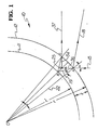
- Figure 1 is a ray trace schematic diagram of a quadrant of a horizontal cross section from an ideal cylindrical transparent container;
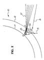
- Figure 2 is a ray trace schematic diagram corresponding to the view of Figure 1, depicting the formation of a virtual image and a ray cluster over a range of inner wall angular deviations;
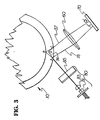
- Figure 3 is an extended ray trace schematic diagram corresponding to that of Figure 1, showing the illumination source and light detection optics; and
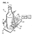
- Figure 4 is a somewhat schematic perspective view of wall thickness gauging apparatus embodying the invention together with related container handling apparatus at the inspection site.
- Reference should now be had to the ray trace schematic diagram of Figure 1, for a discussion of geometric principles underlying the wall thickness measurement system of the invention, as applied to an ideal cylindrical transparent container. This system makes use of a collimated beam of light which illuminates a revolving container, is reflected and refracted by the container sidewall, and measured, substantially within a horizontal reference plane. Due to its narrow width in the reference plane, this beam may be modeled as a ray, and the following discussion assumes this.
- Referring to Figure 1,
incident ray 15 impinges on theouter wall 12 oftransparent container 10 at outer measurement point A, where aportion 19 of the ray enters the wall, is refracted, and travels to inner measurement point B on inner wall 11. A lesser portion ofincident ray 15 is reflected at A ("reflectant ray 18"). At inner measurement point B aportion 25 of the ray is reflected back toward theouter wall 12. At point C most ofray 25 is refracted as "refractant ray 37". A "measurement axis" 22 intersects the outer measurement point A and the axis of symmetry of container 10 (at O). For theideal container 10 of Figure 1 therefractant ray 18 andincident ray 15 each form an angle α at opposite sides ofmeasurement axis 22 and both rays are in the plane of the illustrated container cross-section the horizontal "reference plane"), as arerays - Figure 2 illustrates the formation of a virtual image of the reflection point B of
ray 19. The invention makes use of a rule of Gaussian optics that any ray originating from a point in the object plane of an ideal lens will pass through the corresponding point on the image plane, regardless of the direction of the original ray. The outer surface of the ideal bottle may be modeled as a divergent lens surface with an object plane containing the inner wall reflection point (object point). By the above principle, therefore, a corresponding virtual image point Q will exist which is independent of the direction of the ray emanating from the object point B - thus, independent of the inner wall angle. Due to local angular deviations of the inner wall at point B, the direction of reflectedray 25 can vary over a range of angles, as is shown between extreme points D, E. The within-the-wall projections 34 ofrays 37 therefore vary in their orientations over a range depending on the direction ofray 25, but theseprojections 34 can be seen to converge at point Q. Point Q is thus a virtual image of the inner wall reflection point B. - Considering the virtual image distance S′ of the lens surface between point C (secondary outer measurement point) and virtual image point Q, the paraxial formula for this distance is:
1/s′ = (1-N)/r N/s
Where s - Object distance between point B and secondary outer measurement point C,
N = Index of refraction of container material, and
r = Outer radius of bottle - To take an illustrative example, for N=1.5, r = 1.25 inches, and s = 0.1 inches, this formula gives s′ 0.068 inches. This paraxial formula is only accurate, however, for reflected
rays 25 close to segment BC. - In the technique of the invention, wall thickness t is deduced from the separation distance x between the virtual image point Q and the outer measurement point A, and
lens system 60 is designed so that these two points are in its object plane. Wall thickness may be derived from this separation distance as follows (where r′ represents the inner radius of the bottle; α = incident angle; β = angle between refractedray 19 andmeasurement axis 22; and δ = angle betweenmeasurement axis 22 and radius OB. By Snell's Law, sin (β) = (1/N) sin (α) Applying the law of sines to triangle OBA:
sin(δ+β) = (r/r′)sin(β) - Applying the law of sines to triangle AOQ:
X =AQ = (r)sin(δ)/sin(α+δ) - The wall thickness t may be related to separation distance x by differentiating x with respect to r2:
dx/dr′ = (r/r′)²(sin(α)sin(β))/ (sin²(α+δ)/sin(β+δ)) - In the limit for small wall thickness t, r r′ and δ approaches zero, and the above equation becomes
dx/dr′ = tan(β)/sin(α) - Applicants have shown best results (lowest error) for incidence angles α around 37.5°. For this value of angle α, and N = 1.5, the above derivative equals about 0.7314. This number represents the factor of proportionately between separation distance x and wall thickness t.
- To test the accuracy of the thickness factor at larger wall thicknesses, applicants have performed ray trace computations over a range of wall thicknesses to compare exact wall thickness with an extrapolated linear relationship computed as described above. These computations show that if the linear relationship is assumed, thick sections will be overstated. Hence an appropriate compensation is made by the microprocessor 110 (Figure 4.)
- With reference to the schematic view of Figure 3, in order to translate the
virtual image 36 between points Q,A to a real image outsidecontainer 10, a lens system 50 is provided. Lens 50 is oriented so that both the outer measurement point A and the virtual point Q lie on its object plane, so that the lens' image plane contains the two corresponding image points A′, Q′ In practice, the position of virtual image point Q may vary due to aberrations and other errors in the cylindrical lens surface ofouter container wall 12; accordingly point Q may lie somewhat outside the lens' object plane. - Figures 3 and 4 schematically illustrate a complete wall thickness measurement system embodying the invention. As seen in Figure 4, the system's optical components may be mounted on a
movable base 90, which moves in conjunction withrollers 22 towardcontainer 10 to bring the components into a suitable position for inspection. During inspection, thecontainer 10 is rotated betweenbelt 95 androllers 22 to permit a circumferential scan of wall thickness at a given height.Light source 80 may comprise a laser diode 81 and plano-cylindrical lens lens 83 is separated from laser diode 81 by one focal length.Lenses incident beam 15 from their central axis in the horizontal and vertical planes, respectively. Thus, this lens system focuses the laser light to form a collimatedbeam 15 of high luminance and limited cross section, illustratively a bar measuring 10 mm in height and 0.2 mm in width.Incident beam 15 was oriented at an incidence angle α (Figure 1). Effectively, this beam acts as a single ray in the horizontal reference plane, and the elongated vertical dimension of the beam accommodates vertical misalignment. - As best seen in Figure 3, the reflectant and
refractant rays lens assembly 60 tolinear photosensor array 70. Advantageously,lens 60 comprises a Fresnel or holographic lens, which accommodates a broad range of locations and orientations of therays lens 60 is placed approximately equidistant from the expected location ofvirtual image 36 andsensor array 70, and oriented parallel to the expected (nominal) orientation of theimage 36.Sensor array 70 may consist of a linear array from EG&G Reticon, Sunnyvale, California.Image processor 100 tracks the measurements bysensor array 70 of the separation of points A′, Q′, whilemicroprocessor 110 uses this information and the optical parameters of the system to derive the wall thickness ofcontainer 10.
Claims (6)
using the lens means (60), redirecting the reflectant (18) and refractant (37) rays to a linear detector assembly (70), said linear detector assembly being located at an image plane of the lens means which is conjugate to an object plane nominally containing the front-surface reflection point of the reflectant ray (18) and a virtual image (36) of the rear-surface reflection point of the refractant ray (37); and
measuring (110) the separation of said reflectant and refractant rays at said linear detector assembly as an index of the thickness of the article.
Applications Claiming Priority (2)
| Application Number | Priority Date | Filing Date | Title |
|---|---|---|---|
| US13026687A | 1987-12-08 | 1987-12-08 | |
| US130266 | 1987-12-08 |
Publications (2)
| Publication Number | Publication Date |
|---|---|
| EP0320139A2 true EP0320139A2 (en) | 1989-06-14 |
| EP0320139A3 EP0320139A3 (en) | 1990-08-08 |
Family
ID=22443868
Family Applications (1)
| Application Number | Title | Priority Date | Filing Date |
|---|---|---|---|
| EP88311011A Withdrawn EP0320139A3 (en) | 1987-12-08 | 1988-11-22 | Optical measurement of wall thickness of transparent articles |
Country Status (5)
| Country | Link |
|---|---|
| EP (1) | EP0320139A3 (en) |
| JP (1) | JPH01195305A (en) |
| CN (1) | CN1033479A (en) |
| AU (1) | AU2638388A (en) |
| BR (1) | BR8806289A (en) |
Cited By (14)
| Publication number | Priority date | Publication date | Assignee | Title |
|---|---|---|---|---|
| US5118954A (en) * | 1989-08-25 | 1992-06-02 | French State Represented By The Minister Of Post, Telecommunications And Space | Method and device for the geometrical characterization of transparent tubes |
| US5289265A (en) * | 1991-04-11 | 1994-02-22 | Sumitomo Electric Industries, Ltd. | Method and apparatus for measuring a coating state |
| US5291271A (en) * | 1992-08-19 | 1994-03-01 | Owens-Brockway Glass Container Inc. | Measurement of transparent container wall thickness |
| DE19805200A1 (en) * | 1998-02-10 | 1999-08-19 | Micro Optronic Messtechnik Gmb | Measuring dimensions or distance of transparent objects, e.g. thickness of thin glasses |
| DE19837551A1 (en) * | 1998-08-19 | 2000-03-02 | Peter Wystup | Transparent object wall thickness measuring device; has cylindrical lenses for longitudinal divergence of laser light directed onto measured object and for transverse expansion of object image received by photosensor |
| EP1288613A2 (en) * | 2001-08-30 | 2003-03-05 | Owens-Brockway Glass Container Inc. | Sidewall thickness measurement with a line shaped light beam or for several transparent containers |
| US7060999B2 (en) | 2004-07-09 | 2006-06-13 | Owens-Brockway Glass Container Inc. | Apparatus and method for inspecting ribbed containers |
| EP1862228A1 (en) * | 2006-06-02 | 2007-12-05 | Emhart Glass S.A. | Out of round detector |
| WO2012110749A1 (en) | 2011-02-18 | 2012-08-23 | Msc & Sgcc | Method and device for detecting defects in material distribution in transparent containers |
| US9658057B2 (en) | 2012-10-18 | 2017-05-23 | Msc & Sgcc | Facility for measuring the thickness of the wall of containers |
| WO2019081876A1 (en) | 2017-10-27 | 2019-05-02 | Tiama | Method and device for measuring dimensions by x-rays, on empty glass containers running in a line |
| FR3095506A1 (en) | 2019-04-29 | 2020-10-30 | Tiama | Inspection line for empty glass containers |
| CN116045824A (en) * | 2023-01-04 | 2023-05-02 | 深圳市华众自动化工程有限公司 | High-precision detection device and method based on white light confocal principle |
| CN117109457A (en) * | 2023-10-25 | 2023-11-24 | 山东潍森新材料科技股份有限公司 | Detection device for uniformity of wall thickness of cellulose casing |
Families Citing this family (9)
| Publication number | Priority date | Publication date | Assignee | Title |
|---|---|---|---|---|
| US4859861A (en) * | 1988-05-16 | 1989-08-22 | Becton, Dickinson And Company | Measuring curvature of transparent or translucent material |
| DE102004010311A1 (en) * | 2004-03-03 | 2005-09-22 | Isra Glass Vision Gmbh | Apparatus and method for measuring the thickness of a transparent sample |
| CN100372093C (en) * | 2004-12-10 | 2008-02-27 | 上海宏力半导体制造有限公司 | Method for real-time measuring of milling eliminating rate |
| US7385174B2 (en) * | 2006-06-26 | 2008-06-10 | Owens-Brockway Glass Container Inc. | Apparatus and method for measuring sidewall thickness of non-round transparent containers |
| EP2284481A1 (en) * | 2009-08-05 | 2011-02-16 | Emhart Glass S.A. | Glass container wall thickness measurement using fluorescence |
| CN102809351B (en) * | 2012-08-06 | 2015-03-25 | 北京大恒图像视觉有限公司 | Wall thickness detecting device and wall thickness detecting method for transparent and semitransparent glass bottles |
| CN102853784A (en) * | 2012-08-29 | 2013-01-02 | 中国科学院长春光学精密机械与物理研究所 | Non-contact optical automatic detecting device for linearity of scale shell of grating scale |
| WO2019131840A1 (en) * | 2017-12-27 | 2019-07-04 | 中国塗料株式会社 | Measurement device and measurement method |
| CN114608460B (en) * | 2022-03-21 | 2022-11-22 | 广州矩阵黑格软件科技合伙企业(有限合伙) | Method and system for measuring thickness of bottle preform wall |
Citations (3)
| Publication number | Priority date | Publication date | Assignee | Title |
|---|---|---|---|---|
| US3994599A (en) * | 1974-01-23 | 1976-11-30 | Owens-Illinois, Inc. | Method and apparatus for measuring wall thickness and concentricity of tubular glass articles |
| FR2481445A1 (en) * | 1980-04-23 | 1981-10-30 | Thomson Csf | Measuring geometrical dimensions of optical fibre - during mfr. automatically to obtain electrical signals for controlling operational parameters of mfr. |
| GB2182436A (en) * | 1985-11-05 | 1987-05-13 | Emhart Ind | Optical inspection of transparent or translucent layers |
-
1988
- 1988-11-22 EP EP88311011A patent/EP0320139A3/en not_active Withdrawn
- 1988-11-28 BR BR8806289A patent/BR8806289A/en unknown
- 1988-11-30 AU AU26383/88A patent/AU2638388A/en not_active Abandoned
- 1988-12-08 JP JP31098288A patent/JPH01195305A/en active Pending
- 1988-12-08 CN CN 88108567 patent/CN1033479A/en active Pending
Patent Citations (3)
| Publication number | Priority date | Publication date | Assignee | Title |
|---|---|---|---|---|
| US3994599A (en) * | 1974-01-23 | 1976-11-30 | Owens-Illinois, Inc. | Method and apparatus for measuring wall thickness and concentricity of tubular glass articles |
| FR2481445A1 (en) * | 1980-04-23 | 1981-10-30 | Thomson Csf | Measuring geometrical dimensions of optical fibre - during mfr. automatically to obtain electrical signals for controlling operational parameters of mfr. |
| GB2182436A (en) * | 1985-11-05 | 1987-05-13 | Emhart Ind | Optical inspection of transparent or translucent layers |
Cited By (26)
| Publication number | Priority date | Publication date | Assignee | Title |
|---|---|---|---|---|
| US5118954A (en) * | 1989-08-25 | 1992-06-02 | French State Represented By The Minister Of Post, Telecommunications And Space | Method and device for the geometrical characterization of transparent tubes |
| US5289265A (en) * | 1991-04-11 | 1994-02-22 | Sumitomo Electric Industries, Ltd. | Method and apparatus for measuring a coating state |
| US5291271A (en) * | 1992-08-19 | 1994-03-01 | Owens-Brockway Glass Container Inc. | Measurement of transparent container wall thickness |
| EP0584673B1 (en) * | 1992-08-19 | 1997-07-23 | Owens-Brockway Glass Container Inc. | Measurement of transparent container wall thickness |
| DE19805200A1 (en) * | 1998-02-10 | 1999-08-19 | Micro Optronic Messtechnik Gmb | Measuring dimensions or distance of transparent objects, e.g. thickness of thin glasses |
| DE19805200B4 (en) * | 1998-02-10 | 2006-02-09 | Micro-Optronic-Messtechnik Gmbh | Evaluation method for a thickness measurement on objects |
| DE19837551A1 (en) * | 1998-08-19 | 2000-03-02 | Peter Wystup | Transparent object wall thickness measuring device; has cylindrical lenses for longitudinal divergence of laser light directed onto measured object and for transverse expansion of object image received by photosensor |
| EP1288613B1 (en) * | 2001-08-30 | 2008-01-16 | Owens-Brockway Glass Container Inc. | Transparent container sidewall thickness measurement with a line-shaped light beam |
| EP1288613A2 (en) * | 2001-08-30 | 2003-03-05 | Owens-Brockway Glass Container Inc. | Sidewall thickness measurement with a line shaped light beam or for several transparent containers |
| US6806459B1 (en) * | 2001-08-30 | 2004-10-19 | Owens-Brockway Glass Container Inc. | Measurement of transparent container sidewall thickness |
| US7060999B2 (en) | 2004-07-09 | 2006-06-13 | Owens-Brockway Glass Container Inc. | Apparatus and method for inspecting ribbed containers |
| US7582856B2 (en) | 2006-06-02 | 2009-09-01 | Emhart Glass S.A. | Out of round detector |
| EP1862228A1 (en) * | 2006-06-02 | 2007-12-05 | Emhart Glass S.A. | Out of round detector |
| WO2012110749A1 (en) | 2011-02-18 | 2012-08-23 | Msc & Sgcc | Method and device for detecting defects in material distribution in transparent containers |
| FR2971847A1 (en) * | 2011-02-18 | 2012-08-24 | Tiama | METHOD AND DEVICE FOR DETECTING MATERIAL DISTRIBUTION DEFECTS IN TRANSPARENT CONTAINERS |
| US9244020B2 (en) | 2011-02-18 | 2016-01-26 | Msc & Sgcc | Method and device for detecting defects in material distribution in transparent containers |
| US9658057B2 (en) | 2012-10-18 | 2017-05-23 | Msc & Sgcc | Facility for measuring the thickness of the wall of containers |
| US11549803B2 (en) | 2017-10-27 | 2023-01-10 | Tiama | Method and device for measuring dimensions by X-rays, on empty glass containers running in a line |
| WO2019081876A1 (en) | 2017-10-27 | 2019-05-02 | Tiama | Method and device for measuring dimensions by x-rays, on empty glass containers running in a line |
| FR3095506A1 (en) | 2019-04-29 | 2020-10-30 | Tiama | Inspection line for empty glass containers |
| WO2020221975A1 (en) | 2019-04-29 | 2020-11-05 | Tiama | Line for inspecting empty glass containers |
| US11927542B2 (en) | 2019-04-29 | 2024-03-12 | Tiama | Line for inspecting empty glass containers |
| CN116045824A (en) * | 2023-01-04 | 2023-05-02 | 深圳市华众自动化工程有限公司 | High-precision detection device and method based on white light confocal principle |
| CN116045824B (en) * | 2023-01-04 | 2023-08-15 | 深圳市华众自动化工程有限公司 | High-precision detection device and method based on white light confocal principle |
| CN117109457A (en) * | 2023-10-25 | 2023-11-24 | 山东潍森新材料科技股份有限公司 | Detection device for uniformity of wall thickness of cellulose casing |
| CN117109457B (en) * | 2023-10-25 | 2023-12-26 | 山东潍森新材料科技股份有限公司 | Detection device for uniformity of wall thickness of cellulose casing |
Also Published As
| Publication number | Publication date |
|---|---|
| CN1033479A (en) | 1989-06-21 |
| AU2638388A (en) | 1989-06-08 |
| JPH01195305A (en) | 1989-08-07 |
| BR8806289A (en) | 1989-08-15 |
| EP0320139A3 (en) | 1990-08-08 |
Similar Documents
| Publication | Publication Date | Title |
|---|---|---|
| EP0320139A2 (en) | Optical measurement of wall thickness of transparent articles | |
| US7385710B1 (en) | Measuring device | |
| AU663397B2 (en) | Measurement of transparent container wall thickness | |
| US5929983A (en) | Optical apparatus for determining the height and tilt of a sample surface | |
| HU224630B1 (en) | Apparatus and method for inspecting of container | |
| US6806459B1 (en) | Measurement of transparent container sidewall thickness | |
| JP3345016B2 (en) | Improvements in or relating to surface curvature measuring devices | |
| EP2032937B1 (en) | Apparatus and method for measuring sidewall thickness of non-round transparent containers | |
| US5701178A (en) | Non-damaging flatness and thickness gauge for glass | |
| JPH08114421A (en) | Non-contact type measuring device for measuring thickness ofmaterial body comprising transparent material | |
| JP2618377B2 (en) | Apparatus with F-theta corrected telecentric objective for non-contact measurement | |
| JP3921004B2 (en) | Displacement tilt measuring device | |
| US5440383A (en) | Phase detection deflectometer-type optical device having a large measuring range | |
| WO1993019345A1 (en) | Optical device for checking the flatness and smoothness of a surface | |
| WO2021154075A1 (en) | Angle measuring device for measuring an enclosed angle between two plate members. | |
| US8913254B1 (en) | Measuring device | |
| US3784308A (en) | Method and apparatus for measuring the index of refraction | |
| JPH03186709A (en) | Optical shape measuring method | |
| KR200148536Y1 (en) | Shape error measurement device aspheric mirror | |
| SU938004A1 (en) | Method of part dimension tough-free determination | |
| JP2023521452A (en) | Non-contact dimension measuring device with micrometer resolution | |
| JPS61235707A (en) | Light converging device and film thickness measuring instrument | |
| JPH0727544A (en) | Lens inspecting device | |
| JPS63184003A (en) | Method for measuring thickness of plate by laser beam | |
| JPS58166205A (en) | Method and device for measuring radius of curvature of cubic surface |
Legal Events
| Date | Code | Title | Description |
|---|---|---|---|
| PUAI | Public reference made under article 153(3) epc to a published international application that has entered the european phase |
Free format text: ORIGINAL CODE: 0009012 |
|
| AK | Designated contracting states |
Kind code of ref document: A2 Designated state(s): DE FR GB IT |
|
| PUAL | Search report despatched |
Free format text: ORIGINAL CODE: 0009013 |
|
| PUAF | Information related to the publication of a search report (a3 document) modified or deleted |
Free format text: ORIGINAL CODE: 0009199SEPU |
|
| RAP1 | Party data changed (applicant data changed or rights of an application transferred) |
Owner name: EMHART INDUSTRIES, INC. |
|
| AK | Designated contracting states |
Kind code of ref document: A3 Designated state(s): DE FR GB IT |
|
| D17D | Deferred search report published (deleted) | ||
| PUAL | Search report despatched |
Free format text: ORIGINAL CODE: 0009013 |
|
| AK | Designated contracting states |
Kind code of ref document: A3 Designated state(s): DE FR GB IT |
|
| STAA | Information on the status of an ep patent application or granted ep patent |
Free format text: STATUS: THE APPLICATION IS DEEMED TO BE WITHDRAWN |
|
| 18D | Application deemed to be withdrawn |
Effective date: 19910209 |