EP0320082A1 - Method and apparatus for a flame sensing digital primary safety control for fuel burning devices - Google Patents
Method and apparatus for a flame sensing digital primary safety control for fuel burning devices Download PDFInfo
- Publication number
- EP0320082A1 EP0320082A1 EP88305866A EP88305866A EP0320082A1 EP 0320082 A1 EP0320082 A1 EP 0320082A1 EP 88305866 A EP88305866 A EP 88305866A EP 88305866 A EP88305866 A EP 88305866A EP 0320082 A1 EP0320082 A1 EP 0320082A1
- Authority
- EP
- European Patent Office
- Prior art keywords
- fuel
- fuel burning
- burning device
- electrical power
- ignitor
- Prior art date
- Legal status (The legal status is an assumption and is not a legal conclusion. Google has not performed a legal analysis and makes no representation as to the accuracy of the status listed.)
- Withdrawn
Links
Images
Classifications
-
- F—MECHANICAL ENGINEERING; LIGHTING; HEATING; WEAPONS; BLASTING
- F23—COMBUSTION APPARATUS; COMBUSTION PROCESSES
- F23N—REGULATING OR CONTROLLING COMBUSTION
- F23N1/00—Regulating fuel supply
- F23N1/08—Regulating fuel supply conjointly with another medium, e.g. boiler water
- F23N1/082—Regulating fuel supply conjointly with another medium, e.g. boiler water using electronic means
-
- F—MECHANICAL ENGINEERING; LIGHTING; HEATING; WEAPONS; BLASTING
- F23—COMBUSTION APPARATUS; COMBUSTION PROCESSES
- F23N—REGULATING OR CONTROLLING COMBUSTION
- F23N2223/00—Signal processing; Details thereof
- F23N2223/20—Opto-coupler
-
- F—MECHANICAL ENGINEERING; LIGHTING; HEATING; WEAPONS; BLASTING
- F23—COMBUSTION APPARATUS; COMBUSTION PROCESSES
- F23N—REGULATING OR CONTROLLING COMBUSTION
- F23N2227/00—Ignition or checking
- F23N2227/36—Spark ignition, e.g. by means of a high voltage
Definitions
- the present invention relates to safety control systems in general and, more particularly, to a flame sensing digital primary safety control for fuel burning devices.
- Fuel burning devices such as oil fired heaters, require a safety control system in order to terminate fuel flow to the device and to stop ignition in the event that the fuel does not ignite within a predetermined time period from the start of the heater or if the flame should go out after successful ignition of the fuel.
- Early systems used stack gas temperatures to determine if ignition was successful and if ignition continued in a normal manner.
- Other burner safety controls have used a photocell to monitor the presence or absence of a flame under the so-called "dark start" condition and to monitor the continued presence of a flame during normal operation. Under dark conditions, the photocell resistance was relatively high. Upon ignition, the light from the burning fuel flame caused a drop in the resistance of the photocell. The increased current flow produced by the resistance drop was used as a control signal.
- DC type safety controls lose control when a shorted photocell 11 occurs during normal operation.
- a strong ambient light condition can override the DC control.
- DC type controls are adversely affected by a dirty photocell causing premature turn-off.
- a method for controlling electrical power to a fuel burning device afer ignitiion of the fuel by an electrically powered fuel ignitor comprises the steps of generating an AC normal flame signal representative of and in response to the presence of a normal flame condition of the fuel burning device; and terminating the application of electrical power to the electrically powered fuel ignitor of the fuel burning device if the AC normal flame signal is not generated.
- the invention also includes apparatus for controlling electrical power to a fuel burning device after ignition of the fuel by an electrially powered fuel ignitor, the apparatus comprising means for generating an AC normal flame signal representative of an in response to the presence of a normal flame condition of the fuel burning device; and means for terminating the application of electrical power to the electrically powered fuel ignitor of the fuel burning device if the AC normal flame signal is not generated.
- the flame snesing digital primary safety control for fuel burning devices utilizes both DC and AC control signals depending upon the particular point in a burner cycle.
- a photocell senses the presence or absence of a flame and the condition of the burner flame.
- a DC control signal is generated under a "dark start” condition in the fuel burning device. If proper ignition of the fuel has occured, safety control is transferred to an AC "normal flame” signal that is obtained from the photocell.
- the AC "normal flame” signal is converted into a pulse train that represent the condition of the burner flame. The pulse train is monitored during a predetermined and repeated period with respect to the number of pulses occurring within the time period and the amplitude of the pulses. If the pulse train is not present or pulses are missing or the amplitude of the pulse train fails to meet a pre-established level, the primary safety control terminates power to the electrically powered burner ignitor.
- the safety control 10 controls the application of electrical power from an electrical power line having a phase L1 and a neutral N.
- the electrical power is applied through the safety control 10 to the electrical load of a fuel burning heater 12 having a motor 14 and a fuel ignitor 16.
- the ignitor 16 comprises a conventional ignition transformer and a spark gap (not shown) for igniting a fluid fuel.
- the presence, absence and condition of the burner flame is sensed by a standard photocell 18 which produces output signals as described below that are representative of the presence or absence and the condition of the burner flame.
- the primary digital safety control 10 is powered by a half-wave, well filtered, internal power supply comprising a voltage dropping resistor R10, power diode D1, resistor R5, Zener diode Z1 and filter capacitors C5 and C7.
- the power supply operates from the AC line power source L1 and provides 5 to 15 volts DC with respect to the power line neutral or common side of the AC power line.
- VDD is normally 5.8V during the "ON" state and 13V during a "LOCK-OUT" condition.
- the operation of the safety control 10 is governed by a programmable timer identified in the single Figure as IC-1.
- the Motorola MC14541B Programmable Timer has a 16-stage binary counter, and integrated oscillator for use with an external capacitor and two resistors, an automatic power-on reset circuit and output control logic.
- the timing sequence is initialized by turning on power upon which the power-on reset is enabled and initializes the counter within the specified VDD range. With power on, an external reset pulse can be applied.
- the oscillator Upon release of the initial reset command, the oscillator will oscillate with a frequency determined by the external RC network.
- the 16-stage counter divides the oscillator frequency (F OSC ) with the n th state frequency being f osc /2 n .
- the oscillator can by synchronized to an external clock pulse derived from the power line through R6 to pin 3.
- SCR-1 completes the circuit from pin 8 of the timer IC-1 through resistor R8 and the LED in optical coupler OC-1 to the neutral of the alternating current power line.
- the silicon controlled rectifier SCR-1 is latched "ON" until the cathode-to-anode current is turned off by the timer IC-1.
- the SCR turns on the optical coupler OC-1 which operates as follows: Light from the optical coupler LED causes the triac to turn on thereby allowing alternating current to flow through R9 and into the gate of the power triac which turns the power on to the heater load 12 comprising motor 14 and the ignitor 16.
- a clock pulse supplied through R6 to pin 3 of the programmable timer IC-1 activates the timer binary counter. The countdown starts at power-up and continues until the end of the preset timing sequence, provided that no reset pulse is received at pin 6. If a reset pulse is received, then the programmable timer IC-1 starts its counting cycle all over again, and the "Q" output at pin 8 remains “HIGH”. However, if no reset pulse is received before the end of the timing sequence, the pin 8 "Q" output becomes “LOW” or at logic “0". If the "Q" output goes "LOW", the optical coupler OC-1 is turned off with the result that the power triac is also turned off thereby terminating electrical power to the electrical load of the heater 12.
- a chopper transistor Q1 is biased into saturation by resistors R2 and R7. With Q1 saturated, the collector of Q1 and the reset (pin 6) of the programmable timer IC-1 are held at logic "0" thereby preventing the timer from being reset except by a signal pulse applied to the base of chopper transistor Q1 that is strong enough to override the bias and turn off Q1.
- capacitor C3 quickly charges to a logic "HIGH” (pin 6) by current flow through resistor R4 and diode D3, thereby resetting the programmable timer IC-1.
- the pule train forces the timer to stay in a "reset” mode so that the output "Q" will remain “HIGH” thereby allowing alternating current line power to be applied through the power triac to the heater electrical load of motor 14 and ignitor 16.
- the pulses applied to the reset (pin 6) of the timer become weak or missing for a period of time greater than the timing interval, plus the time required for capacitor C3 to discharge to 1/2 voltage, the timer IC-1 will "time out” thereby turning off the electrical power to the burner motor 14 and fuel ignitor 16.
- Capacitor C6 and R3 form a "snubber" circuit for both the power triac and the OC-1 triac. Electromagnetic interference is supressed by capacitors C3, C4 and C8.
- One of the features of the digital primary safety control is that if the photocell 18 is shorted during operation, no pulse will appear at the timer reset (pin 6) and shutdown of the heater motor and ignitor will occur at the end of the timing period. Furthermore, if the photocell circuit is exposed to ambient light during normal operation, this light cannot take control of the circuit. This operation is in distinct contrast to the conventional DC safety control circuits in which a shorted condition or high ambient light level, which occurs during a normal flame condition, will override the DC control after a successful "dark start" and allow the fuel burning heater to operate in an unsafe mode.
Abstract
A flame sensing digital primary safety control for fuel burning devices and method therefor are disclosed. A photocell senses the presence or absence and the condition of the burner flame. A DC control signal for the primary safety control is generated under a "dark start" condition in the fuel burning device. Once proper ignition of the fuel has occurred, safety control is transferred to an AC "normal flame" signal that is obtained from the photocell. The use of an AC safety control signal provides a greater degree of safety for the fuel burning device because problems with the photocell, such as a shorting of the cell, produce a "fail safe" condition in contrast to a DC signal operated safety control.
Description
- The present invention relates to safety control systems in general and, more particularly, to a flame sensing digital primary safety control for fuel burning devices.
- Fuel burning devices, such as oil fired heaters, require a safety control system in order to terminate fuel flow to the device and to stop ignition in the event that the fuel does not ignite within a predetermined time period from the start of the heater or if the flame should go out after successful ignition of the fuel. Early systems used stack gas temperatures to determine if ignition was successful and if ignition continued in a normal manner. Other burner safety controls have used a photocell to monitor the presence or absence of a flame under the so-called "dark start" condition and to monitor the continued presence of a flame during normal operation. Under dark conditions, the photocell resistance was relatively high. Upon ignition, the light from the burning fuel flame caused a drop in the resistance of the photocell. The increased current flow produced by the resistance drop was used as a control signal. If the signal did not occur within a predetermined time period after starting the heater, the heater was shut down. If a proper flame was established during the predetermined time period, the light from the flame reduced the resistance of the photocell and this reduction in resistance produced a DC control signal representing a "normal flame" condition. In the event that there was a "flame out", the resistance of the photocell increased to its "dark start" resistance level thereby causing a reduction in current flow. The reduction in current flow was used to shut down the heater. A representative example of a flame responsive photocell safety system is disclosed in US-A-3,672,811.
- The use of a direct current (DC) control signal from the photocell presents a number of safety problems. First, the DC type safety controls lose control when a shorted photocell 11 occurs during normal operation. Secondly, a strong ambient light condition can override the DC control. Furthermore, DC type controls are adversely affected by a dirty photocell causing premature turn-off.
- In accordance with the invention, a method for controlling electrical power to a fuel burning device afer ignitiion of the fuel by an electrically powered fuel ignitor, comprises the steps of generating an AC normal flame signal representative of and in response to the presence of a normal flame condition of the fuel burning device; and terminating the application of electrical power to the electrically powered fuel ignitor of the fuel burning device if the AC normal flame signal is not generated.
- The invention also includes apparatus for controlling electrical power to a fuel burning device after ignition of the fuel by an electrially powered fuel ignitor, the apparatus comprising means for generating an AC normal flame signal representative of an in response to the presence of a normal flame condition of the fuel burning device; and means for terminating the application of electrical power to the electrically powered fuel ignitor of the fuel burning device if the AC normal flame signal is not generated.
- In one construction, the flame snesing digital primary safety control for fuel burning devices utilizes both DC and AC control signals depending upon the particular point in a burner cycle. A photocell senses the presence or absence of a flame and the condition of the burner flame. A DC control signal is generated under a "dark start" condition in the fuel burning device. If proper ignition of the fuel has occured, safety control is transferred to an AC "normal flame" signal that is obtained from the photocell. The AC "normal flame" signal is converted into a pulse train that represent the condition of the burner flame. The pulse train is monitored during a predetermined and repeated period with respect to the number of pulses occurring within the time period and the amplitude of the pulses. If the pulse train is not present or pulses are missing or the amplitude of the pulse train fails to meet a pre-established level, the primary safety control terminates power to the electrically powered burner ignitor.
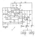
- The invention will best be understood from a detail description of a preferred embodiment of the invention, selected for purposes of illustration and shown in the accompanying single Figure which is a partial block diagram and schematic of the digital primary safety control.
- Turning now to the single Figure, there is shown a digital
primary safety control 10. Thesafety control 10 controls the application of electrical power from an electrical power line having a phase L1 and a neutral N. The electrical power is applied through thesafety control 10 to the electrical load of afuel burning heater 12 having amotor 14 and afuel ignitor 16. Theignitor 16 comprises a conventional ignition transformer and a spark gap (not shown) for igniting a fluid fuel. The presence, absence and condition of the burner flame is sensed by astandard photocell 18 which produces output signals as described below that are representative of the presence or absence and the condition of the burner flame. - The primary
digital safety control 10 is powered by a half-wave, well filtered, internal power supply comprising a voltage dropping resistor R10, power diode D1, resistor R5, Zener diode Z1 and filter capacitors C5 and C7. The power supply operates from the AC line power source L1 and provides 5 to 15 volts DC with respect to the power line neutral or common side of the AC power line. VDD is normally 5.8V during the "ON" state and 13V during a "LOCK-OUT" condition. The operation of thesafety control 10 is governed by a programmable timer identified in the single Figure as IC-1. - One suitable programmable timer is the MC14541B Programmable Timer manufactured and sold by Motorola. The Motorola MC14541B Programmable Timer has a 16-stage binary counter, and integrated oscillator for use with an external capacitor and two resistors, an automatic power-on reset circuit and output control logic. The timing sequence is initialized by turning on power upon which the power-on reset is enabled and initializes the counter within the specified VDD range. With power on, an external reset pulse can be applied. Upon release of the initial reset command, the oscillator will oscillate with a frequency determined by the external RC network. The 16-stage counter divides the oscillator frequency (FOSC) with the nth state frequency being fosc/2n. Alternatively, the oscillator can by synchronized to an external clock pulse derived from the power line through R6 to
pin 3. - Given this configuration of the programmable time IC-1, normal operation commences upon application of the AC power from L1 and N (neutral) to the automatic power-up (reset) circuit of IC-1. At this point, the timer initializes all counters to a time base of zero. At time base zero, the "Q" output at
pin 8 of the timer is at logic "HIGH". If the resistance of thephotocell 18 is above the value required for a "dark start" (greater than 10K ohms), SCR-1 will be turned on by the current through resistor R1 and the Zener STS-1. This current constitutes a DC "dark start" signal. The turning on of SCR-1 completes the circuit frompin 8 of the timer IC-1 through resistor R8 and the LED in optical coupler OC-1 to the neutral of the alternating current power line. The silicon controlled rectifier SCR-1 is latched "ON" until the cathode-to-anode current is turned off by the timer IC-1. The SCR turns on the optical coupler OC-1 which operates as follows: Light from the optical coupler LED causes the triac to turn on thereby allowing alternating current to flow through R9 and into the gate of the power triac which turns the power on to theheater load 12 comprisingmotor 14 and theignitor 16. - A clock pulse supplied through R6 to
pin 3 of the programmable timer IC-1 activates the timer binary counter. The countdown starts at power-up and continues until the end of the preset timing sequence, provided that no reset pulse is received atpin 6. If a reset pulse is received, then the programmable timer IC-1 starts its counting cycle all over again, and the "Q" output atpin 8 remains "HIGH". However, if no reset pulse is received before the end of the timing sequence, thepin 8 "Q" output becomes "LOW" or at logic "0". If the "Q" output goes "LOW", the optical coupler OC-1 is turned off with the result that the power triac is also turned off thereby terminating electrical power to the electrical load of theheater 12. Once the programmable time "Q" output goes "LOW", a "lock-out" diode D2 clamps the timer's reset (pin 6) "LOW". This prevents the "Q" output atpin 8 from being turned on again until the AC power has been removed for a period of approximately 10 seconds. - A chopper transistor Q1 is biased into saturation by resistors R2 and R7. With Q1 saturated, the collector of Q1 and the reset (pin 6) of the programmable timer IC-1 are held at logic "0" thereby preventing the timer from being reset except by a signal pulse applied to the base of chopper transistor Q1 that is strong enough to override the bias and turn off Q1. When Q1 is turned off, capacitor C3 quickly charges to a logic "HIGH" (pin 6) by current flow through resistor R4 and diode D3, thereby resetting the programmable timer IC-1.
- When a normal combustion flame is seen by the
photocell 18, the resulting changes in resistance of the photocell is such that an AC signal is produced at the junction of a voltage divider consisting of resistor R1 and thephotocell 18. This alternating "normal flame" signal is coupled to the base of chopper transistor Q1 through coupling capacitor C-1. When a continuous AC "normal flame" wavetrain is applied to the base of chopper transistor Q1, a corresponding continuous train of pulses is applied to the reset (pin 6) of the programmable timer during the timing interval. The pule train forces the timer to stay in a "reset" mode so that the output "Q" will remain "HIGH" thereby allowing alternating current line power to be applied through the power triac to the heater electrical load ofmotor 14 andignitor 16. However, if the pulses applied to the reset (pin 6) of the timer become weak or missing for a period of time greater than the timing interval, plus the time required for capacitor C3 to discharge to 1/2 voltage, the timer IC-1 will "time out" thereby turning off the electrical power to theburner motor 14 andfuel ignitor 16. - Capacitor C6 and R3 form a "snubber" circuit for both the power triac and the OC-1 triac. Electromagnetic interference is supressed by capacitors C3, C4 and C8.
- One of the features of the digital primary safety control is that if the
photocell 18 is shorted during operation, no pulse will appear at the timer reset (pin 6) and shutdown of the heater motor and ignitor will occur at the end of the timing period. Furthermore, if the photocell circuit is exposed to ambient light during normal operation, this light cannot take control of the circuit. This operation is in distinct contrast to the conventional DC safety control circuits in which a shorted condition or high ambient light level, which occurs during a normal flame condition, will override the DC control after a successful "dark start" and allow the fuel burning heater to operate in an unsafe mode. - The following Parts List is illustrative of one way of implementing the digital primary safety control of the present invention.
PARTS LIST REFERENCE DESIGNATION DESCRIPTION C1 Capacitor, 10 F, 25 VDC C3 Capacitor, .047 F, C4 Capacitor, .068 F, C5,C7 Capacitor, 100 F, 16 VDC C8 Capacitor, .01 F, 16 VDC STS-1 Zener, .25W, 10V, 5% Q1 Transistor (Motorola MPSa17) C6 Capacitor, .047 F, 600 VDC R1,R11 Resistor, .25W, 3.3K, 5% R2 Resistor, .25W, 39K, 5% R3 Resistor, .25W, 270 OHM, 5% R4 Resistor, .25W, 22K, 5% R5 Resistor, .25W, 270 OHM, 5% R6 Resistor, .25W, 15 MEG OHM, 5% R7 Resistor, .25W, 15K, 5% R8 Resistor, .25W, 270 OHM, 5% R9 Resistor, .25W, 270 OHM, 5% R10 Resistor, 10W, 7K, 10% IC-1 OSC/Timer Digital Logic Chip (Motorola MC14541B) OC-1 Optical Coupler (Motorola MOC635A) Z1 ZENER, 1W, 15V, 10% (Motorola IN4744) D1,D2,D3 Diode, 1A, 600V SCR-1 SCR, 30V PWR TRIAC Triac, 10A, 500V
Claims (12)
1. A method for controlling electrical power to a fuel burning device after ignition of the fuel by an electrically powered fuel ignitor, the method comprising the steps of generating the AC normal flame signal representative of and in response to the presence of a normal flame condition of the fuel burning device; and terminating the application of electrical power to the electrically powered fuel ignitor of the fuel burning device if the AC normal flame signal is not generated.
2. A method according to claim 1, wherein the application of electrical power to the electrically powered fuel ignitor of the fuel burning device is terminated if the AC normal flame signal is not generated during a predetermined time period.
3. A method according to claim 1 or claim 2, wherein the AC normal flame signal is converted into a pulse train and the application of electrical power to the electrically powered fuel ignitor is terminated in response to the pulse train having a predetermined characteristic.
4. A method according to claim 3, wherein the pulse train predetermined characteristic is the amplitude of the pulse train.
5. A method according to claim 3, wherein the pulse train predetermined characteristic is the existence of at least one pulse of sufficient amplitude during a predetermined time period.
6. A method according to any one of the preceding claims, further comprising generating a DC dark start signal representative of and in response to the presence of a dark start condition of the fuel burning device; applying electrical power to the fuel ignitor of the fuel burning device in response to the DC dark start signal; and terminating the application of electrical power to the fuel ignitor of the fuel burning device if the AC normal flame signal is not generated within a first predetermined time period after generation of the DC dark start signal.
7. An apparatus for controlling electrical power to a fuel burning device after ignition of the fuel by an electrically powered fuel ignitor (16), the apparatus comprising means for generating an AC normal flame signal representative of and in response to the presence of a normal flame condition of the fuel burning device; and means for terminating the application of electrical power to the electrically powered fuel ignitor of the fuel burning device if the AC normal flame signal is not generated.
8. An apparatus according to claim 8, wherein the terminating means is arranged to terminate the application of electrical power to the electrically powered fuel ignitor of the fuel burning device if the AC normal flame signal is not generated during a predetermined time period.
9. An apparatus according to claim 7 or claim 8, wherein the generating means is arranged to convert the AC normal flame signal into a pulse train; and the terminating means is arranged to terminate the application of electrical power to the electrically powered fuel ignitor in response to the pulse train having a predetermined characteristic.
10. An apparatus according to claim 9, wherein the pulse train predetermined characteristic is the amplitude of the pulse train.
11. An apparatus according to claim 9, wherein the pulse train predetermined characteristic is the existence of at least one pulse of sufficient amplitude during a predetermined time period.
12. An apparatus according to any one of claims 7 to 11, further comprising means for generating a DC dark start signal representative of and in response to the presence of a dark star condition of the fuel burning device; and means for applying electrical power to the fuel ignitor of the fuel burning device in response to the DC dark start signal; the terminating means being arranged to terminate the application of electrical power to the fuel ignitor of the fuel burning device if the AC normal flame signal is not generated within a first predetermined time period after generation of the DC dark start signal.
Applications Claiming Priority (2)
| Application Number | Priority Date | Filing Date | Title |
|---|---|---|---|
| US13006387A | 1987-12-08 | 1987-12-08 | |
| US130063 | 1987-12-08 |
Publications (1)
| Publication Number | Publication Date |
|---|---|
| EP0320082A1 true EP0320082A1 (en) | 1989-06-14 |
Family
ID=22442886
Family Applications (1)
| Application Number | Title | Priority Date | Filing Date |
|---|---|---|---|
| EP88305866A Withdrawn EP0320082A1 (en) | 1987-12-08 | 1988-06-28 | Method and apparatus for a flame sensing digital primary safety control for fuel burning devices |
Country Status (1)
| Country | Link |
|---|---|
| EP (1) | EP0320082A1 (en) |
Cited By (3)
| Publication number | Priority date | Publication date | Assignee | Title |
|---|---|---|---|---|
| DE19841475C1 (en) * | 1998-09-10 | 2000-02-03 | Electrowatt Tech Innovat Corp | Flame monitoring system for gas-, oil- or coal-fired burner |
| EP0884536A3 (en) * | 1997-06-13 | 2000-05-24 | Kigass Electronics Ltd | Control system for a fuel burning appliance |
| US6652266B1 (en) * | 2000-05-26 | 2003-11-25 | International Thermal Investments Ltd. | Flame sensor and method of using same |
Citations (9)
| Publication number | Priority date | Publication date | Assignee | Title |
|---|---|---|---|---|
| US2807758A (en) * | 1954-07-30 | 1957-09-24 | Honeywell Regulator Co | Transistor flame detector |
| US2825012A (en) * | 1955-02-14 | 1958-02-25 | Honeywell Regulator Co | Flame detector |
| FR2121953A6 (en) * | 1971-01-13 | 1972-08-25 | Thermoflex App | |
| US3713766A (en) * | 1971-09-07 | 1973-01-30 | Emerson Electric Co | Oil burner control system |
| FR2186118A5 (en) * | 1972-05-25 | 1974-01-04 | Webster Electric Co Inc | |
| US3829276A (en) * | 1973-05-21 | 1974-08-13 | Sundstrand Corp | Burner control |
| US3947219A (en) * | 1975-02-24 | 1976-03-30 | Sundstrand Corporation | Burner control with interrupted ignition |
| US4167389A (en) * | 1977-11-02 | 1979-09-11 | Emerson Electric Co. | Oil burner primary control for interrupted ignition system |
| FR2454055A1 (en) * | 1979-04-09 | 1980-11-07 | Honeywell Inc | FLAME SENSITIVE CONTROL CIRCUIT |
-
1988
- 1988-06-28 EP EP88305866A patent/EP0320082A1/en not_active Withdrawn
Patent Citations (9)
| Publication number | Priority date | Publication date | Assignee | Title |
|---|---|---|---|---|
| US2807758A (en) * | 1954-07-30 | 1957-09-24 | Honeywell Regulator Co | Transistor flame detector |
| US2825012A (en) * | 1955-02-14 | 1958-02-25 | Honeywell Regulator Co | Flame detector |
| FR2121953A6 (en) * | 1971-01-13 | 1972-08-25 | Thermoflex App | |
| US3713766A (en) * | 1971-09-07 | 1973-01-30 | Emerson Electric Co | Oil burner control system |
| FR2186118A5 (en) * | 1972-05-25 | 1974-01-04 | Webster Electric Co Inc | |
| US3829276A (en) * | 1973-05-21 | 1974-08-13 | Sundstrand Corp | Burner control |
| US3947219A (en) * | 1975-02-24 | 1976-03-30 | Sundstrand Corporation | Burner control with interrupted ignition |
| US4167389A (en) * | 1977-11-02 | 1979-09-11 | Emerson Electric Co. | Oil burner primary control for interrupted ignition system |
| FR2454055A1 (en) * | 1979-04-09 | 1980-11-07 | Honeywell Inc | FLAME SENSITIVE CONTROL CIRCUIT |
Cited By (4)
| Publication number | Priority date | Publication date | Assignee | Title |
|---|---|---|---|---|
| EP0884536A3 (en) * | 1997-06-13 | 2000-05-24 | Kigass Electronics Ltd | Control system for a fuel burning appliance |
| DE19841475C1 (en) * | 1998-09-10 | 2000-02-03 | Electrowatt Tech Innovat Corp | Flame monitoring system for gas-, oil- or coal-fired burner |
| EP0985881A2 (en) | 1998-09-10 | 2000-03-15 | Electrowatt Technology Innovation AG | Flame monitoring system |
| US6652266B1 (en) * | 2000-05-26 | 2003-11-25 | International Thermal Investments Ltd. | Flame sensor and method of using same |
Similar Documents
| Publication | Publication Date | Title |
|---|---|---|
| US3853455A (en) | Burner control apparatus | |
| CA1142246A (en) | Burner control system | |
| CA1051768A (en) | Spark ignited recycling ignition system with interlocking gas valve control | |
| US5158447A (en) | Primary gas furnace control | |
| US4298335A (en) | Fuel burner control apparatus | |
| CA1060973A (en) | Burner control system | |
| US3861854A (en) | Flame monitoring system | |
| US5470223A (en) | Microprocessor controlled fuel and ignition control for a fuel burning device | |
| US4662838A (en) | Fuel burner control system | |
| US3447880A (en) | Control system for fluid fuel burners | |
| US4323824A (en) | Low voltage fluorescent operating circuit | |
| US3619097A (en) | Safety timed burner control system | |
| US3441356A (en) | Pulsed spark gas ignition and fuel control system | |
| US3938937A (en) | Fuel ignition control arrangement | |
| EP0320082A1 (en) | Method and apparatus for a flame sensing digital primary safety control for fuel burning devices | |
| US4359315A (en) | Apparatus for fuel ignition system including complete cycling of flame relay prior to trial for ignition | |
| US6169369B1 (en) | Low cost, precision electronic starter | |
| US4836770A (en) | Primary gas furnace control | |
| CA1083248A (en) | Burner control system with primary safety switch | |
| US4299557A (en) | Fuel burner control circuit | |
| US4459099A (en) | Fuel and ignition control | |
| US3399948A (en) | Solid state ignition circuit for fuel bruners | |
| US3734676A (en) | Electrically energizable control system for a fuel burner | |
| AU605663B2 (en) | Microprocessor-based controller with synchronous reset | |
| US4034270A (en) | Self-inhibiting spark generating arrangement |
Legal Events
| Date | Code | Title | Description |
|---|---|---|---|
| PUAI | Public reference made under article 153(3) epc to a published international application that has entered the european phase |
Free format text: ORIGINAL CODE: 0009012 |
|
| AK | Designated contracting states |
Kind code of ref document: A1 Designated state(s): AT BE CH DE ES FR GB GR IT LI LU NL SE |
|
| 17P | Request for examination filed |
Effective date: 19891205 |
|
| 17Q | First examination report despatched |
Effective date: 19920130 |
|
| STAA | Information on the status of an ep patent application or granted ep patent |
Free format text: STATUS: THE APPLICATION IS DEEMED TO BE WITHDRAWN |
|
| 18D | Application deemed to be withdrawn |
Effective date: 19920610 |