EP0319974A1 - Multi-purpose container - Google Patents
Multi-purpose container Download PDFInfo
- Publication number
- EP0319974A1 EP0319974A1 EP88120530A EP88120530A EP0319974A1 EP 0319974 A1 EP0319974 A1 EP 0319974A1 EP 88120530 A EP88120530 A EP 88120530A EP 88120530 A EP88120530 A EP 88120530A EP 0319974 A1 EP0319974 A1 EP 0319974A1
- Authority
- EP
- European Patent Office
- Prior art keywords
- members
- frame member
- container
- purpose container
- holding
- Prior art date
- Legal status (The legal status is an assumption and is not a legal conclusion. Google has not performed a legal analysis and makes no representation as to the accuracy of the status listed.)
- Granted
Links
Images


Classifications
-
- B—PERFORMING OPERATIONS; TRANSPORTING
- B65—CONVEYING; PACKING; STORING; HANDLING THIN OR FILAMENTARY MATERIAL
- B65D—CONTAINERS FOR STORAGE OR TRANSPORT OF ARTICLES OR MATERIALS, e.g. BAGS, BARRELS, BOTTLES, BOXES, CANS, CARTONS, CRATES, DRUMS, JARS, TANKS, HOPPERS, FORWARDING CONTAINERS; ACCESSORIES, CLOSURES, OR FITTINGS THEREFOR; PACKAGING ELEMENTS; PACKAGES
- B65D88/00—Large containers
- B65D88/02—Large containers rigid
- B65D88/12—Large containers rigid specially adapted for transport
-
- B—PERFORMING OPERATIONS; TRANSPORTING
- B65—CONVEYING; PACKING; STORING; HANDLING THIN OR FILAMENTARY MATERIAL
- B65D—CONTAINERS FOR STORAGE OR TRANSPORT OF ARTICLES OR MATERIALS, e.g. BAGS, BARRELS, BOTTLES, BOXES, CANS, CARTONS, CRATES, DRUMS, JARS, TANKS, HOPPERS, FORWARDING CONTAINERS; ACCESSORIES, CLOSURES, OR FITTINGS THEREFOR; PACKAGING ELEMENTS; PACKAGES
- B65D88/00—Large containers
- B65D88/52—Large containers collapsible, i.e. with walls hinged together or detachably connected
- B65D88/526—Large containers collapsible, i.e. with walls hinged together or detachably connected with detachable side walls
- B65D88/528—Large containers collapsible, i.e. with walls hinged together or detachably connected with detachable side walls all side walls detached from each other to collapse the container
-
- B—PERFORMING OPERATIONS; TRANSPORTING
- B65—CONVEYING; PACKING; STORING; HANDLING THIN OR FILAMENTARY MATERIAL
- B65D—CONTAINERS FOR STORAGE OR TRANSPORT OF ARTICLES OR MATERIALS, e.g. BAGS, BARRELS, BOTTLES, BOXES, CANS, CARTONS, CRATES, DRUMS, JARS, TANKS, HOPPERS, FORWARDING CONTAINERS; ACCESSORIES, CLOSURES, OR FITTINGS THEREFOR; PACKAGING ELEMENTS; PACKAGES
- B65D88/00—Large containers
- B65D88/02—Large containers rigid
- B65D88/12—Large containers rigid specially adapted for transport
- B65D88/121—ISO containers
-
- B—PERFORMING OPERATIONS; TRANSPORTING
- B65—CONVEYING; PACKING; STORING; HANDLING THIN OR FILAMENTARY MATERIAL
- B65D—CONTAINERS FOR STORAGE OR TRANSPORT OF ARTICLES OR MATERIALS, e.g. BAGS, BARRELS, BOTTLES, BOXES, CANS, CARTONS, CRATES, DRUMS, JARS, TANKS, HOPPERS, FORWARDING CONTAINERS; ACCESSORIES, CLOSURES, OR FITTINGS THEREFOR; PACKAGING ELEMENTS; PACKAGES
- B65D88/00—Large containers
- B65D88/02—Large containers rigid
- B65D88/12—Large containers rigid specially adapted for transport
- B65D88/122—Large containers rigid specially adapted for transport with access from above
- B65D88/124—Large containers rigid specially adapted for transport with access from above closable top
- B65D88/126—Large containers rigid specially adapted for transport with access from above closable top by rigid element, e.g. lid
-
- B—PERFORMING OPERATIONS; TRANSPORTING
- B65—CONVEYING; PACKING; STORING; HANDLING THIN OR FILAMENTARY MATERIAL
- B65D—CONTAINERS FOR STORAGE OR TRANSPORT OF ARTICLES OR MATERIALS, e.g. BAGS, BARRELS, BOTTLES, BOXES, CANS, CARTONS, CRATES, DRUMS, JARS, TANKS, HOPPERS, FORWARDING CONTAINERS; ACCESSORIES, CLOSURES, OR FITTINGS THEREFOR; PACKAGING ELEMENTS; PACKAGES
- B65D90/00—Component parts, details or accessories for large containers
- B65D90/0006—Coupling devices between containers, e.g. ISO-containers
-
- B—PERFORMING OPERATIONS; TRANSPORTING
- B65—CONVEYING; PACKING; STORING; HANDLING THIN OR FILAMENTARY MATERIAL
- B65D—CONTAINERS FOR STORAGE OR TRANSPORT OF ARTICLES OR MATERIALS, e.g. BAGS, BARRELS, BOTTLES, BOXES, CANS, CARTONS, CRATES, DRUMS, JARS, TANKS, HOPPERS, FORWARDING CONTAINERS; ACCESSORIES, CLOSURES, OR FITTINGS THEREFOR; PACKAGING ELEMENTS; PACKAGES
- B65D90/00—Component parts, details or accessories for large containers
- B65D90/0026—Corner fittings characterised by shape, configuration or number of openings
-
- B—PERFORMING OPERATIONS; TRANSPORTING
- B65—CONVEYING; PACKING; STORING; HANDLING THIN OR FILAMENTARY MATERIAL
- B65D—CONTAINERS FOR STORAGE OR TRANSPORT OF ARTICLES OR MATERIALS, e.g. BAGS, BARRELS, BOTTLES, BOXES, CANS, CARTONS, CRATES, DRUMS, JARS, TANKS, HOPPERS, FORWARDING CONTAINERS; ACCESSORIES, CLOSURES, OR FITTINGS THEREFOR; PACKAGING ELEMENTS; PACKAGES
- B65D90/00—Component parts, details or accessories for large containers
- B65D90/008—Doors for containers, e.g. ISO-containers
-
- B—PERFORMING OPERATIONS; TRANSPORTING
- B65—CONVEYING; PACKING; STORING; HANDLING THIN OR FILAMENTARY MATERIAL
- B65D—CONTAINERS FOR STORAGE OR TRANSPORT OF ARTICLES OR MATERIALS, e.g. BAGS, BARRELS, BOTTLES, BOXES, CANS, CARTONS, CRATES, DRUMS, JARS, TANKS, HOPPERS, FORWARDING CONTAINERS; ACCESSORIES, CLOSURES, OR FITTINGS THEREFOR; PACKAGING ELEMENTS; PACKAGES
- B65D2585/00—Containers, packaging elements or packages specially adapted for particular articles or materials
- B65D2585/68—Containers, packaging elements or packages specially adapted for particular articles or materials for machines, engines, or vehicles in assembled or dismantled form
- B65D2585/6802—Containers, packaging elements or packages specially adapted for particular articles or materials for machines, engines, or vehicles in assembled or dismantled form specific machines, engines or vehicles
- B65D2585/686—Containers, packaging elements or packages specially adapted for particular articles or materials for machines, engines, or vehicles in assembled or dismantled form specific machines, engines or vehicles vehicles
- B65D2585/6867—Containers, packaging elements or packages specially adapted for particular articles or materials for machines, engines, or vehicles in assembled or dismantled form specific machines, engines or vehicles vehicles automobiles
-
- B—PERFORMING OPERATIONS; TRANSPORTING
- B65—CONVEYING; PACKING; STORING; HANDLING THIN OR FILAMENTARY MATERIAL
- B65D—CONTAINERS FOR STORAGE OR TRANSPORT OF ARTICLES OR MATERIALS, e.g. BAGS, BARRELS, BOTTLES, BOXES, CANS, CARTONS, CRATES, DRUMS, JARS, TANKS, HOPPERS, FORWARDING CONTAINERS; ACCESSORIES, CLOSURES, OR FITTINGS THEREFOR; PACKAGING ELEMENTS; PACKAGES
- B65D2590/00—Component parts, details or accessories for large containers
- B65D2590/0008—Coupling device between containers
- B65D2590/0016—Lashings means
-
- B—PERFORMING OPERATIONS; TRANSPORTING
- B65—CONVEYING; PACKING; STORING; HANDLING THIN OR FILAMENTARY MATERIAL
- B65G—TRANSPORT OR STORAGE DEVICES, e.g. CONVEYORS FOR LOADING OR TIPPING, SHOP CONVEYOR SYSTEMS OR PNEUMATIC TUBE CONVEYORS
- B65G2201/00—Indexing codes relating to handling devices, e.g. conveyors, characterised by the type of product or load being conveyed or handled
- B65G2201/02—Articles
- B65G2201/0294—Vehicle bodies
Definitions
- This invention relates to a multi-purpose container in which various cargoes are loaded, being bulked small when no cargo is housed.
- Containers in which limited sort of cargoes are housed for example a refregerating container, a tank container, a container only for animals etc., are constructed most suitably to the housing cargoes. So remarkable difficulty during loading operation does not recognized.
- a popular dry-container houses general merchandises mainly, but the sort of the housing cargoes is not limited.
- Loading of the cargoes is achieved by using folk-lift car etc. through an opened door of the container. So the loading operation is not suitable for a long sized cargo, a bulk cargo for its weight (especially a bulk cargo in a length direction of the container) etc.
- open-top containers provided disassemble top member, top surface of which is covered by canvas cover to protect from intruding water, or flatrack containers provided four pillars standing at four corners, because the cargoes for exampie glass plates, plant products, bulk bulldozers, iron materials, may be housed in the container by using a crane.
- the frequency of transporting empty containers is nearly same as the frequency of transporting filled containers, so the space occupied by the empty container is same as the space occupied by the filled container, thereby to decrease the utilizing efficiency of ships, trucks, freight trains and accumulating place for empty containers.
- the containers are mainly 20 feet in length and 40 feet in length, each size fall under ISO standard.
- Each total weight is arranged 20 tons and 30 tons respectively, and the maximum height is arranged 8 feet 6 inches to conform the Road Traffic Control Law and the traffic control for example the height of tunnels.
- the standard of container is examining to change the total weight and the maximum height of the 20 feet sized container to 24 tons and 9 feet 6 inches respectively.
- the multi-purpose container in accordance with the present invention being assembled to be a cube, comprises: quadrilateral main frame members, a rectangular bottom frame member, side frame members, a roof frame member, holes formed at the connecting portion of each members, connecting members inserted in said hole in extractable manner, two pairs of holding members for holding said members piled, being possible to be fixed to corner metal fittings provided at the top portion of said main frame members, each pair of holding members being possible to be connected one another, a plurality of openings having inner flange, formed at the predetermined position of said side frame members, and foldable door members attached to said openings in an openable manner.
- the roof frame member comprises an edge member substantially formed as a square frame and a quadrilateral cover attached to the edge member in a disattachable manner, to cover the top opening of the edge member.
- the opening is shaped as eight cornered polygon, the eight cornered polygon is formed by cutting away four corners of rectangle elongated in the length direction of the container.
- the inner flange is fixed at the edge portion of the opening as one body, and an arc-shaped projection in the sectional figure are formed at the top of the edge portion of the inner flange.
- the door member is housed to the step formed by the inner flange, is connected to the side frame member rotatable only outward direction, is also foldable in tbe outward direction.
- holes communicated each other are formed at the edge portion of the door member and the inner flange, and screw wedges extractable from only inside of the container are inserted in the holes.
- a connecting member holding member united sealing member is further housed in each holes.
- a step is further formed at the edge portion of the members, thereby to ensure the ccnnection of neibouring members, more preferably in this case, a sealing member is further fixed to the step.
- the connecting portion of the bottom frame member with the side frame member is a guiding projection united fitting member of the side frame member
- tbe conneoting portion of the side frame member with the roof frame member is a guiding projection united fitting member of the roof frame member
- upward projections are formed at the longer side of the bottom frame member, and fixing members for lashing are fixed at the predetermined position of the upward projections.
- each pair of holding members comprises a holding member attached to the corner metal fittings of the main frame member in a disattachable manner, and a holding member attached to the holding member in a disattachable manner, and connecting members are housed in one of the holding member, more preferably in this case, each pair of holding members are attached to the main frame member to suit the top surface of the roof frame member.
- the main frame members, the bottom frame member, the side frame members and the roof frame member are assembled to form the cubic multi-purpose container satisfying the strength established with the ISO standard, by inserting the connecting members into the holes. Loading or unloading cargoes is achieved after assembling the members. On the contrary, assembling the members is achieved after loading cargoes on the bottom member.
- Each pair of holding members are attached to the corner metal fittings provided at the top portion of the main frame members by the connecting members, and each pair of holding members are connected as one body by the connecting members.
- Intensity of the container seems to be lowered because of forming a plurality of openings at the side frame members. But the intensity of the container is nearly same as the intensity of the conventional container fall under ISO standard, when the door members are closed to contact to the inner flanges. On the contrary, the intensity is lowered when the door members are opened. The door members are opened only when loading or unloading of cargoes are achieved, and the container cargoes are loading or unloading therein or therefrom, is not piled, thereby inconvenience does not occur.
- the multi-purpose container thus assembled must satisfy requisites for protecting from extracting inner cargo from outside after performing seal-lock at the lock portion of the door, and for confirming all connecting member from outside, thereby to transport cargoes secureiy and certainly.
- Fig. 1 is an exploded perspective view of a dry container which is an instance of the multi-purpose container in accordance with the present invention, while Fig. 2 is a perspective view thereof showing the assembled state.
- the dry container has a bottom frame member 1, a front main frame member 2, a rear main frame member 3, a pair of side frame members 4, a roof frame member 5, a roof cover 5′, an inner shelf member 6 and two pairs of holding members 9.
- the bottom frame member 1 is a rigid plate whose width is 8 feet and length is about 40 feet.
- Each short edge of the bottom frame member 1 is shaped as a first connecting projection 11 in the shape of somewhat narrow width and out out at its bottom side (see Fig. 5).
- Each long edge of the bottom frame member 1 is projected upward, and a guiding projection 12 having a predetermined height is shaped at the top edge of the long edge (see Fig. 6).
- Tapered holes 13 and 14 are formed at the first connecting projection 11 and the guiding projection 12 at every predetermined interval respectively.
- a downward projection 16 is formed at the predetermined position of the bottom surface of the first connecting projection 11, thereby to ensure touch with the main frame member.
- a projection 15 for fixing position is formed adjacent to the guiding projection 12.
- Fixing members 17 for lashing are fixing at the predetermined position of the guiding projection 12.
- the side frame member 4 is a rigid plate whose width is 8 feet 6 inches and length is 40 feet. Each short edge of the side frame member 4 is shaped as a second connecting projection 41 in the shape of somewhat narrow width and cut out at its outer side (see Fig. 1).
- a guiding groove 42 is formed at the bottom surface of the downward edge of the side frame member 4, thereby to engage the guiding projection 12.
- a guiding projection 42′ is shaped at the upward long edge of the side frame member 4, thereby to engage guiding grooves 53 formed at the bottom surface of the roof frame member 5.
- a sealing member 46 is housed interior of the guiding groove 42.
- a skirt member 47 is projected downward from the outer surface of the portion having the guiding groove 42, thereby to touch with the side face of the bottom frame member 1.
- Tapered holes 48 are formed at the portion having the guiding groove 42, thereby to communicate with the tapered holes 14 formed at the guiding projection 12.
- Tapered holes 48 are also formed at the guiding projection 42′.
- Tapered holes 48 are also formed at the second projection 4i, thereby to communicate with tapered holes 25 of the main frame member described later. Holes engagable with the projections 15 (not shown) and a projection 15′ to fix the position of the roof frame member 5 are formed at the predetermined position of the side frame member 4.
- Three eight-cornered-polygon shaped openings 49 are formed at the predetermined position, distances therebetween are equal, and openable door members 8 are attached to the openings 49.
- An inner flange 50 is fixed in one body to the inside of the frame member 4, corresponding to the opening 49, thereby to form a step for housing the door member 8.
- Tapered holes 81 communicated each other are formed at the predetermined position of the inner flange 50 and the door member 8.
- a contacting portion 82 is formed at the projected edge of the inner flange 50.
- a tapered contacting portion 83 being able to contact with the contacting portion 82 is formed to the inner side of the door member 8.
- a sealing member 84 being able to contact with the inner flange 50 is attached next to the tapered contacting portion 83.
- the door member 8 is rotatably connected to the side frame member 4 by hinge members 85.
- the door member 8 is devided into two plates at its center, and each devided plates are 10 connected each other foldably outward direction by hinge members 85. Contacting portions of the devided plates are step shaped, each step is formed in the inverse shape each other.
- the hinge members 85 are buried in the door member 8 and the side frame member 4.
- the roof frame member 5 is a rigid plate whose width is 8 feet and length is about 40 feet. A large opening 51 is formed at the center of the rigid plate.
- the roof cover 5′ is attached to the strong plate to cover the large opening 51 in a disattachable manner.
- Each short edge of the roof frame member 5 is shaped as a third connecting projection 52 in the shape of somewhat narrow width and cut out at its top side (see Fig. 1).
- the height of the roof cover 5′ is equal to the height of holding members 9 described later.
- guiding grooves 53 are formed at the bottom surface of the roof frame member 5, thereby to engage with the guiding grooves 42′.
- a guiding projection 54 is shaped at the top surface of the roof frame member 5, thereby to engage with the top cover 5′.
- a sealing member 55 is housed interior of the guiding groove 53.
- Tapered holes 56 are formed at the portion having the guiding groove 53, thereby to communicate with the tapered holes 48 formed at the guiding projection 42′.
- Tapered holes 56 are also formed at the third connecting projection 52, thereby to communicate with tapered holes formed at the main frame member described later.
- Skirt members 57 are projected downward from the long edge of the roof frame member 5, thereby to touch with the side face of each side frame member 4.
- a guiding groove 54′ to engage the guiding projection 54 is formed at the side bottom surface of the roof cover 5′.
- a sealing member 55′ is housed interior of the guiding groove 54′.
- Tapered holes 56′ are formed at the portion having the guiding groove 54′, thereby to communicate with the tapered holes 56 formed at the guiding projection 54.
- the front main frame member 2 comprises a square frame 21 and a double door 22.
- the square frame 21 is to be touch with the outer surface of the connecting projections 11, 41 and 52 shaped at the short edge of the bottom frame member 1, a pair of the side frame members 4 and the roof frame member 5.
- the double door 22 is fixed to the square frame 21.
- the rear inner portion of the square frame 21 is cut out to form a step 23.
- the step 23 is the tapered shape.
- Sealing members 24 is fixed to the step 23 against to engaging portions 11d, 41d and 52d fixed to the projecting surface of the connecting projections 11, 41 and 52.
- Tapered holes 25 are formed at the square frame 21 to communicate tapered holes 13, 48 and 56. Corner metal fittings 26 each having engaging holes, are fixed to the corner of the square frame 21.
- the rear main frame member 3 is different from the front main frame member 2, that is a shut plate 32 is fixed to the square frame 31 instead of the double door 22.
- the inner shelf member 6 is a rigid plate having the predetermined width.
- the predetermined length adjacent to the front main frame member 2 is cut off and connected to the rest in a rotatable up and down manner. When it is rotated downward, loading and unloading of automobiles by driving the vary automobiles are permitted. On the contrary. when it is rotated upward, loaded automobiles are kept horizontally.
- the inner shelf member 6 is housed in the assembled container in a disattachable manner, and is supported by a driving device driven by pressured oil and guiding member 62, thereby to move up and down.
- Dents 61 to receive wheels of automobiles loaded in the upper chamber, are formed at the inner shelf member 6 at the shifted position to the roof of automobiles loaded in the down chamber.
- the dent 61 is formed at the predetermined depth to prevent touch the bottom surface of the automobile body with the inner shelf member 6.
- Wedges 10′ are inserted to the communicated tapered holes as shown in Figs. 5, 6 and 7.
- the pair of holding members 9 comprises a first holding member 9a attached to the main frame member 2 and 3, and a second holding member 9b attached to the first holding member 9a.
- the first holding member 9a comprises a cubic frame 9a to house the short edge of the bottom frame member 1 and connecting members 7 fixed to both ends of the cubic frame 91.
- a main locking member 73 is fixed to the predetermined position of the connecting member 7, thereby to connect with the corner metal fitting 26.
- a lock system including the main locking member 73 may be attached to the connecting member 7 in a disattachable manner.
- the second holding member 9b comprises a cubic frame 91′ to house the short edge of the roof frame member 5 and connecting members 7′ fixed to both ends of the cubic frame 91′.
- the second holding member 9b is held on the roof frame member 5 by guiding pieces (not shown) attached to the roof frame member 5 in a disattachable manner, being parallel to the first holding member 9a.
- Both connecting members 7 and 7′ have nearly same construction one another. More specifically, the connecting member 7 comprises a casing 71, a rotating member 72 housed in the casing rotatably, the main locking member 73 rotating and going in and out follow the rotation of the rotating member 72 and a driving wire 74 to rotate the rotating member 72.
- the casing 71 is formed a space 71a corresponding to a corner metal fitting nearly equal in shape to the corner metal fitting 26 of the front main frame member 2 and a space 71c to house tbe rotating member 72 rotatably, interior thereof.
- the rotating member 12 comprises a disc plate 72a formed a groove 72b for winding the driving wire 74 at the outer surface and a screw shaft 72c projected at the center of the disc plate 72a.
- Click stop balls 72f energized upwardly by springs 72e, are housed in holes formed at the bottom edge ward position of the disc plate 72a.
- Engaging dents 71d are formed at the predetermined position of the space 71c, thereby to control the rotating position of the disc plate 72a by engaging the click stop balls 72f with the engaging dents 71d.
- the main locking member 73 comprises a screw pipe 73a engaged with the screw shaft 72c, an engaging head 73b engagable with the corner metal fitting 26 and a spring 73c housed in the screw pipe 73a, in the compressed condition.
- the engaging head 73b is formed rectanglar figure in plan view and the top surface thereof is projected as the equilateral triangle.
- An engaging projection 73f is formed at the predetermined position of the outer surface of the casing 71, thereby to limit the rotation of the main locking member 73 by engaging the engaging head 73b with the engaging projection 73f.
- the main locking member 73 is moved to and from the corner metal fitting 26 following the movement of the pair of holding members 9.
- the main locking member 73 is also rotated following the rotation of the rotating member 72 by the effect of the spring 73c, within the regulated limit by the engaging projection 73f.
- the regulated limit is about 90 degrees.
- the main locking member 73 is allowed to rotate over the regulated limit, thereby to move to and from according to the relative rotation of the screw shaft 72c and the screw pipe 73a. That is, after the engaging head 73b is engaged with the engaging projection 73f, the rotating member 72 is rotated in one direction with keeping the engaged condition, thereby to move the main locking member 73 to the casing 71 against the energizing force of the spring 73c.
- the rotating member 72 is rotated in opposite direction with keeping the engaged condition, thereby to move the main locking member 73 from the casing 71 utilizing the energizing force of the spring 73c. Accordingly, the engaging head 73b is regulated the rotation by the engaging projection 73f, thereby to achieve engagement and disengagement to the corner metal fitting 26 easily.
- the connecting member 7′ has the construction nearly same to the connecting member 7, except the following points.
- First different point is that the length of the main locking member is different one another.
- Second different point is that the rotating member and the main locking member are housed at the folded condition, in the second holding member 91′. Brackets (not shown) and set pins (not shown) are disattachably attached to the folding portion.
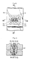
- Figs 12, 13 and 14 illustrate the configuration of a wedge 10 screwed into tapered holes.
- Wedge inserting holes 101 and 102 communicated each other are formed at the predetermined position of one frame member and another frame member.
- a screw bolt 103 and a screw wedge 104 are housed in the wedge inserting hole 101, and a back-stop screw bolt 105 is housed in the wedge inserting hole 102.
- the wedge inserting hole 101 has a tapered portion only at the position adjacent to the wedge inserting hole 102, and the wedge inserting hole 102 is formed tapered covering its total length.
- the screw bolt 103 is attached only rotatably to a rod-shaped holding member 106 fixed to the predetermined position of the wedge inserting hole 101.
- the screw wedge 104 is formed cylindrical shape nearly same as the wedge inserting hole 101, at its base portion, and is formed tapered cylindrical shape nearly same as the wedge inserting hole 102, at its top portion.
- a groove 107 engageable with the rod-shaped holding member 106 is formed at the base portion of the screw wedge 104.
- the wedge inserting hole 102 is anti-penetratable hole.
- a screwed hole for allowing screwed movement in/out of the back-stop screw bolt 105 is formed interior of the wedge inserting hole 102.
- the back-stop screw bolt 105 is allowed screw engagement with the top portion of the screw wedge 104, by screwing the back-stop screw bolt 105 in the screwed hole at the condition that a sealing member 108 is interposed therebetween.
- the wedge inserting holes 101 and 102 and the screw wedges 104 are elongated in one direction, thereby to ensure the movement in/out of the screw wedge 104.
- a sealing member 109 is fixed to one frame member.
- An engaging projection 110 contacted to the sealing member 109 is fixed to another frame member.
- both wedge inserting holes 101 and 102 are communicated each other by fixing the position of both frame members accurately, the screw bolt 103 is rotated in one direction, then the screw wedge 104 is slided toward the wedge inserting hole 102 of another frame member, thereby to engage the top portion of the screw wedge 14 with the wedge inserting hole 102, because the rotation of the screw wedge 104 is inhibited. Then the back-stop screw bolt 105 engages with the top portion of the screw wedge and press the sealing member 108 strongly, by screwing the back-stop screw bolt 105 in through the screwed hole, thereby to connect both frame members as one body and to prevent water etc. from intruding.
- the multi-purpose container is assembled by connecting frame members each other with using the oonnecting members mentioned above. After sealing the door members 8, 22 of the multi purpose container housing cargoes therein, the rotation of the screw bolt 103 and the movement in/out of the screw wedge 104 by operating the screw bolt 103 from outside of the container are impossible, because the top portion of the rotation inhibited screw wedge 104 is screwed with the back-stop screw bolt 105, thereby to prevent cargoes from taking out by disassembling the multi-purpose container. Accordingly, cargoes are allowed to unload only when the door members 8, 22 are opened after unsealed the door members 8, 22.
- the side frame members 4 are connected with the bottom frame member 1 by engaging the guiding grooves 42 formed at the bottom surface of the side frame members 4 with the guiding projections 12 shaped at the top surface of the bottom frame member 1, and inserting wedges 10′ into the communicated holes 48 and 14 (see Fig. 6).
- the top edge of the guiding projection 12 is contacted hardly to the sealing member 46 housed interior of the guiding groove 42, and the skirt member 47 is contacted to the side face of the bottom frame member 1.
- entering the wind and water are securely prevented, and increasing the pressing force to extremely high is securely prevented, thereby to prevent damage of the sealing member 46.
- the door member 8 is prevented from opening only when opening operation is applied from the outside of the multi-purpose container, because wedges 10 are screwed in the tapered holes 81 of the inner flange 50 and the door member 8.
- the guide grooves 53 are engaged with the guide projections 42′ shaped at the top edge of the side frame members 4, and the wedges 10′ are inserted into the communicated tapered holes 48 and 45 one another, thereby to maintain the predetermined distance between the top edges of the side frame members 4. Then the cubic pipe like container body portion is formed.
- the sealing members 55 housed interior of the guiding grooves 53 and the skirt members 57 contacted to the outer surface of the side frame members 4 cooperate to prevent wind and water from entering and to prevent contacting pressure from increasing for diminishing the damage of the sealing members 55, similarly to the above-mentioned engaging portion.
- the inner shelf member 6 is attached at the predetermined position of the container body portion. The short edge side portion of the inner shelf member 6 adjacent to the front main frame member 2, is rotated downward to form a slope way, if necessary.
- the square frame 21 of the front main frame member 2 is attached to contact each outside of the first connecting projection 11 of the bottom frame member 1, the second connecting projection 41 of the side frame member 4 and the third connecting projection 52 of the roof frame member 5, then the wedges 10′ are inserted into the communicated tapered holes 25 and tapered holes 13, 48 and 56 (see Fig. 5), thereby to connect the front main frame member 2 with the bottom frame member 1, the side frame members 4 and the roof frame member. More particularly, the engagement of the square frame 21 with the bottom frame member 1, the side frame members 4 and the roof frame member 5 is achieved by engaging steps one another.
- the first connecting projection 11 engages with the tapered inner surface of the square frame 21, the edge surfaces and the cutaway steps of the bottom frame member 1, side frame members 4 and roof frame member 4 are contacted with pressure respectively, with the square frame 21, thereby to diminish the damage of the sealing member 24, and to prevent wind and water from intruding.
- the rear main frame member 3 is also attached to the bottom frame member 1, side frame members 4 and roof frame member 5 in the same manner as the front main frame member 2, thereby to prevent wind and water from intruding.
- the first holding members 9a are fixed to each main frame members 2, 3 by holding and fixing the connecting members 7 to the corner metal fittings 26 of each main frame members 2 and 3, the holding and fixing are achieved by inserting the main locking members 73 into the corner metal fittings 26 and rotating the rotating members 72.
- the second holding members 9b are also fixed to the roof frame members 5 as the same manner above mentioned.
- the fixing operation may be executed before or after loading cargoes into the container.
- the roof cover 5′ is attached to the roof frame member 5 to cover the large opening 51, thereby to form the closed up space to house cargoes.
- the dry container having about 40 feet length is formed by achieving above-mentioned operations, thereby to load cargoes easily loadable in the assembled container after the above-mentioned operations.
- cargo hardly loadable in the assembled container is to load at half way of the assemblying operations, for example only the side frame members 4 are attached to the bottom frame member 1, by using crames etc. After that, rest assembling operation should be executed.
- Loading automobiles on the inner shelf member 6 may be achieved by a crane through the large opening 51 of the roof frame member 5. If a driving device driven by pressured oil bearable to great load, is used, loading automobiles on the inner shelf member 6 is executed firstly, then loading automobiles on the bottom frame member 1 is executed after moving the inner shelf member 6 upwardly, and finally, moving the inner shelf member 6 downwardly and attaching the roof cover 5′ to the roof frame member 5 is executed. That is, four automobiles are loaded in the container having 40 feet length, and the interior thereof is certainly kept water proofed conditions, thereby to transport automobiles securely.
- a bulk space for loading is obtained interior of the container by moving the inner shelf member 6 upwardly to be housed in the roof frame member 5.
- hot coils When hot coils should be loaded, in the state mentioned above, hot coils are loaded in good order by using folk-lift car etc. after opened the door member 22 of the front main frame member 2, then hot coils thus loaded are fixed at the predetermined position by fixing lashings to the fixing members 17. As a result, loading hot coils in the container having 40 feet length through the door member 22, spends great deal of labor and time. To decrease, this disadvantage, hot coils should be loaded in the container through the door member 8, thereby to lessen the deal of labor and time. That is, the folk-lift car etc. are allowed running freely at the outside of the container, and the folk-lift car etc. should be driven most carefully only when hot coils are moved from outside to inside of the container and hot coils are moved to the predetermined position in the container. When lashings are applied to the loaded hot coils, moving in/out of the operator is easily done through openings 49, thereby to remarkably decrease the danger accompanying loading, and to remarkabiy increase the efficiency of lashing operation.
- the strength of the assembled multi-purpose container in the width direction is assured by the strength of both main frame members 2 and 3.
- the strength of the assembled multi-purpose container in the length direction is assured by the engagement of the square frames 21 and 31 of both main frame members 2 and 3 with the top edges and the steps cut away of the bottom frame member 1, side frame members 4 and roof frame member 5, and the connection of the uneven engaging portion of guiding projections with the guiding grooves using inserted wedges.
- the strength of the assembled multi-purpose container at its entirety is nearly the same with the conventional container satisfying the ISO standard. Preventing the sealing members from damage and preventing wind and water from entering is well accomplished.
- the sequence of the assembling operations is not limited to the above-mentioned sequence, but one of the main frame members is connected to the bottom frame member 1 at the halfway of the assembling and the other main frame member is connected thereto finally are allowed.
- the multi-purpose container having the construction above-mentioned is able to be piled on the flat rack container by attaching the second holding members 9b to the bottom side of each main frame member 2 and 3 to increase the height of the connecting portion, thereby to utilize the space in holds etc. efficiently.
- positioning members may be formed at the corresponding frame member, to be positioned easily to the connecting members attached in projected manner
- the multi-purpose container When recoverinng the multi-purpose container, that is transforming the empty multi-purpose container, the multi-purpose container is disassembled into each frame members by executing operations in inverse sequence to the assembling operations. Then each frame members are piled up as one body by the following operations.
- the inner shelf member 6 is piled on the bottom frame member 1 between the guiding projections 12, both main frame members 2 and 3 are piled on the top face of the guiding projections 12 of the bottom frame member 1, then the side frame members 4 and roof cover 5′ are piled thereon, finally the roof frame member 5 is piled thereon, thereby to reduce the volume to the minimum.
- the contacting portion of both main frame members 2 and 3 to the guiding projections 12 have already been cut away.
- the first connecting projections 11 are held by the first holding members 9a, and the third connecting projections 52 are held by the second holding members 9b, then the wedges 10′ are inserted into the communicated tapered holes to fix each holding members with each frame members.
- the main locking members fixed to one holding member is connected with the connecting members fixed to another holding member, thereby to reduce the entire volume and to be one body (see Fig. 19).
- engaging portions are formed at the contating surface of the bottom frame member 1 and the main frame members 2 and 3 to ensure the connection of both main frame members 2 and 3.
- the engaging portions are positioned and have the predetermined size not to avoid the operability of assembling and disassembling and not to lessen the strength of the assembled multi-purpose container. Housing the inner shelf member 6 interior of the roof frame member 5 and the roof cover 5′, and housing the driving device driven by pressured oil etc. interior of the roof frame member 5 and the roof cover 5′ are allowed.
- Wedges 10′ and rubber plugs 10 ⁇ having been used to assemble the multi-purpose container are housed interior of housing boxes (not shown) through an openable door.
- the housing boxes are conventional housing boxes attachable to a dry container etc., and are attached to the multi-purpose container in a surplus space.
- the driving device driven by pressured oil and the guiding member 62 to move the inner shelf member 6 and others are housed in the downdard space of the roof cover 5′, if necessary.
- multi-purpose container having 40 feet length may also be disassembled itself, and cargoes may also be loaded and unloaded into and out from the multi-purpose container
- the engaging part of the square frames 21 and 31 of the main frame members 2 and 3 with the bottom frame member 1, side frame members 4 and roof frame member 5 may be constructed by contacting projections one another, or by contacting side face one another and contacting top and bottom uneven faces formed by cutting away, as shown in Fig. 20, thereby to connect the container body to main frame members.
- a tapered portion and a flat portion follows the tapered portion may be formed at the end of the guiding projections 12 of the bottom frame member 2, as shown in Fig.
- cone shaped projections may be formed in the surplus space, a tapered portion, a flat portion and cone shaped holes may be formed at the edge of the side frame member 4 engaged with the tapered portion, flat portion and cone shaped projections respectively, thereby to locate the side frame members 4 accurately.
- the engaging part of the side frame members 4 with the roof frame member 5 may be constructed as above-mentioned manner, thereby to locate the roof frame member 5 accurately.
- Figs. 22 and 23 are perspective views of the main portion of the bottom frame member 1′ applied to the container having 9 feet 6 inches height, having other configuration.
- Height of the side frame member is kept equal to the above embodiment because every frame members should be got together in a small bulk when the container is disassembled. Thereby, the difference of the height should be taken charge of by the bottom frame member 1′.
- the above configuration of the bottom frame member 1′ is done to satisfy the demand mentioned above.
- the longer side of the bottom frame member 1′ is constructed by a side plate 111 bent at the several positions thereof, thereby to obtain the bottom frame member 1′ taller by 1 feet 6 inches than the bottom frame member 1 mentioned earlier.
- Further cross members 112 are fixed to the bottom frame member 1′ at every 600 mm distance, thereby to obtain enough rigidness.
- a top surface plate (not shown) is further fixed to the bottom frame member 1′.
- Reinforcement members 113 are fixed to the predetermined position of the side plate 111, corresponding to the cross member.
- a fixing member 17 for fixing lashing is fixed to the predetermined position of the reinforcement member 113, as one body.
- a guiding projection 12 is fixed to the top edge of the side plate 111. Tapered holes 14 are formed at the predetermined position of the guiding projection 12.
- Screw wedges and screw bolts etc. may be used instead of the wedges 10′.
- the wedge and rubber plug may be made as one body.
- a wedge holding member united sealing member may be attached interior of the tapered hole.
- the positioning of the guiding projection 12 and the guiding groove 42 may be reversed.
- a cut away dent may be formed instead of the guiding groove 42.
- the multi-purpose container may be a tall container.
- a pair of holding members 9 may be made as one body.
Abstract
Description
- This invention relates to a multi-purpose container in which various cargoes are loaded, being bulked small when no cargo is housed.
- Conventionally, various containers corresponding to a variety of cargo are supplied, thereby to reliably protect cargoes during transportation on land or sea.
- Containers in which limited sort of cargoes are housed, for example a refregerating container, a tank container, a container only for animals etc., are constructed most suitably to the housing cargoes. So remarkable difficulty during loading operation does not recognized.
- A popular dry-container houses general merchandises mainly, but the sort of the housing cargoes is not limited.
- Loading of the cargoes is achieved by using folk-lift car etc. through an opened door of the container. So the loading operation is not suitable for a long sized cargo, a bulk cargo for its weight (especially a bulk cargo in a length direction of the container) etc.
- Accordingly, open-top containers provided disassemble top member, top surface of which is covered by canvas cover to protect from intruding water, or flatrack containers provided four pillars standing at four corners, because the cargoes for exampie glass plates, plant products, bulk bulldozers, iron materials, may be housed in the container by using a crane.
- At the arrival place, unloading operation using cranes similarly to the departure place is carried out, thereby to load or unload cargoes to or from the container in trouble occasionally.
- In the case that cargoes are hot coils, a plurality of hot coils should be loaded in good order by fixing them in turns carried into the container through the door of the main frame member at the predetermined position using wedges and applying lashing. Then the efficiency of loading operation goes down and the accuracy of fixed position of hot coils goes down. As a result, deformation and/or damage of hot coils will happen because of various force act to hot coils during transportation, in spite of loading hot coils in the container with spending great deal of labor and time.
- Accordingly, this loading system of hot coils is not put to practical use.
- In the transportation using the container, the frequency of transporting empty containers is nearly same as the frequency of transporting filled containers, so the space occupied by the empty container is same as the space occupied by the filled container, thereby to decrease the utilizing efficiency of ships, trucks, freight trains and accumulating place for empty containers.
- More specifically, the containers are mainly 20 feet in length and 40 feet in length, each size fall under ISO standard.
- Each total weight is arranged 20 tons and 30 tons respectively, and the maximum height is arranged 8
feet 6 inches to conform the Road Traffic Control Law and the traffic control for example the height of tunnels. The standard of container is examining to change the total weight and the maximum height of the 20 feet sized container to 24 tons and 9feet 6 inches respectively. - These containers are constructed in not permitting disassemblance because enough strength and protection from water are needed considering transportation on sea in the piled condition, thereby to occupy the same space regardless of empty or full. Accordingly, the same space as the space of the ships, trucks, freight trains when transporting the cargoes, is needed when transporting the empty containers, thereby to increase the energy waste rate per the volume of transporting cargoes.
- This disadvantage will be remarkable when the standard of container is improved as aforementioned.
- It is an object of the present invention to produce a novel multi-purpose container.
- It is another object of the present invention to load and unload variable cargoes easily.
- It is a further object of the present invention to increase the space efficiency for loading automobiles into the multi-purpose container.
- It is still another object of the present invention to decrease the space needed for transporting the container in which no cargo is loaded.
- It is a still further object of the present invention to protect cargoes housed in the container from being stolen.
- In order to achieve the objects above-mentioned, the multi-purpose container in accordance with the present invention, being assembled to be a cube, comprises:
quadrilateral main frame members,
a rectangular bottom frame member,
side frame members,
a roof frame member,
holes formed at the connecting portion of each members,
connecting members inserted in said hole in extractable manner,
two pairs of holding members for holding said members piled, being possible to be fixed to corner metal fittings provided at the top portion of said main frame members, each pair of holding members being possible to be connected one another,
a plurality of openings having inner flange, formed at the predetermined position of said side frame members, and
foldable door members attached to said openings in an openable manner. - Preferably, the roof frame member comprises an edge member substantially formed as a square frame and a quadrilateral cover attached to the edge member in a disattachable manner, to cover the top opening of the edge member.
- Preferably, the opening is shaped as eight cornered polygon, the eight cornered polygon is formed by cutting away four corners of rectangle elongated in the length direction of the container.
- Preferably, the inner flange is fixed at the edge portion of the opening as one body, and an arc-shaped projection in the sectional figure are formed at the top of the edge portion of the inner flange.
- Preferably in these cases, the door member is housed to the step formed by the inner flange, is connected to the side frame member rotatable only outward direction, is also foldable in tbe outward direction.
- More preferably, holes communicated each other are formed at the edge portion of the door member and the inner flange, and screw wedges extractable from only inside of the container are inserted in the holes.
- Preferably, a connecting member holding member united sealing member is further housed in each holes.
- Preferably, a step is further formed at the edge portion of the members, thereby to ensure the ccnnection of neibouring members, more preferably in this case, a sealing member is further fixed to the step.
- Preferably, the connecting portion of the bottom frame member with the side frame member is a guiding projection united fitting member of the side frame member, and tbe conneoting portion of the side frame member with the roof frame member is a guiding projection united fitting member of the roof frame member.
- More preferably, upward projections are formed at the longer side of the bottom frame member, and fixing members for lashing are fixed at the predetermined position of the upward projections.
- Preferably, each pair of holding members comprises a holding member attached to the corner metal fittings of the main frame member in a disattachable manner, and a holding member attached to the holding member in a disattachable manner, and connecting members are housed in one of the holding member, more preferably in this case, each pair of holding members are attached to the main frame member to suit the top surface of the roof frame member.
- According to the multi-purpose container having the arrangement above-mentioned, the main frame members, the bottom frame member, the side frame members and the roof frame member are assembled to form the cubic multi-purpose container satisfying the strength established with the ISO standard, by inserting the connecting members into the holes. Loading or unloading cargoes is achieved after assembling the members. On the contrary, assembling the members is achieved after loading cargoes on the bottom member. Each pair of holding members are attached to the corner metal fittings provided at the top portion of the main frame members by the connecting members, and each pair of holding members are connected as one body by the connecting members.
- Intensity of the container seems to be lowered because of forming a plurality of openings at the side frame members. But the intensity of the container is nearly same as the intensity of the conventional container fall under ISO standard, when the door members are closed to contact to the inner flanges. On the contrary, the intensity is lowered when the door members are opened. The door members are opened only when loading or unloading of cargoes are achieved, and the container cargoes are loading or unloading therein or therefrom, is not piled, thereby inconvenience does not occur.
- The multi-purpose container thus assembled must satisfy requisites for protecting from extracting inner cargo from outside after performing seal-lock at the lock portion of the door, and for confirming all connecting member from outside, thereby to transport cargoes secureiy and certainly.
- When recovering the multi-purpose container, disattach two pairs of holding members from main frame members at first, disconnect each members by pulling out all connecting members at second, then pile up each members in the state that main frame members are positioned at the intermediate position as sandwitched by other members, thereby to decrease bulk at its entirety. After that, the edge portion of the top piled member end the edge portion of the bottom piled member are held by each holding member of each pair of holding members respectively, then both holding members are moved apart to the permitted limit of the connecting member, maintained the connected state of both holding members, thereby to get together comprising member of the multi-purpose container. The volume thus got together is decreased to the one several-th of the volume of the assembled multi-purpose container.
- Further objects and advantages of this present invention will become apparent as the following description proceeds and the features of novelty which characterize this present invention are pointed out with particularly in the claims annexed hereto.
-
- Fig. 1 is an exploded perspective view of multi-purpose container in accordance with an embodiment of the present invention,
- Fig. 2 is a perspective view of multi-purpose container in the assembled state,
- Fig. 3 is a partially cutaway perspective view showing the attached state of the door member to the side frame member,
- Fig. 4 is an enlarged section view taken along the line IV-IV in Fig. 3.
- Fig. 5 is a vertical section view showing the connecting portion of the front main frame member and the bottom frame member,
- Fig. 6 is a vertical section view showing the connecting portion of the bottom frame member and the side frame member,
- Fig. 7 is a vertical section view showing the connecting portion of the roof frame member and the side frame member,
- Fig. 8 is a side view showing the main portion of the holding member,
- Fig. 9 is a vertical section view showing the main portion of the holding member,
- Fig. 10 is a bottom view showing the main portion of the holding member in the connected state,
- Fig. 11 is a horizontal section view taken along the line XI-XI in Fig. 8,
- Fig. 12 is a front view of a screw-wedge,
- Fig. 13 is a section view taken along the line XIII-XIII in Fig. 12,
- Fig. 14 is a section view taken along the line XIV-XIV in Fig. 12,
- Fig. 15 is a perspective view taken away part of outer members showing the automobiles loaded state,
- Figs 16 and 17 are vertical section views showing the automobiles loaded state,
- Fig. 18 is a perspective view showing the automobiles loaded state with top cover is being to attach to the roof frame member,
- Fig. 19 is a perspective view showing the got together state for recovery,
- Fig. 20 is a vertical section view showing the connecting portion of the front main frame member and the bottom frame member, embloyed other construction,
- Fig. 21 is a vertical section view showing the connecting portions of the front main frame member, the bottom frame member and the side frame member, embloyed other construction, and
- Figs. 22 and 23 are partially cutaway perspective view of the bottom frame member, employed another construction.
- Fig. 1 is an exploded perspective view of a dry container which is an instance of the multi-purpose container in accordance with the present invention, while Fig. 2 is a perspective view thereof showing the assembled state.
- In Figs. 1 and 2, the dry container has a
bottom frame member 1, a frontmain frame member 2, a rearmain frame member 3, a pair ofside frame members 4, aroof frame member 5, aroof cover 5′, aninner shelf member 6 and two pairs of holdingmembers 9. - Now referring to Figs. 3, 4, 5, 6 and 7, the multi-purpose container is described in detail.
- The
bottom frame member 1 is a rigid plate whose width is 8 feet and length is about 40 feet. Each short edge of thebottom frame member 1 is shaped as a first connectingprojection 11 in the shape of somewhat narrow width and out out at its bottom side (see Fig. 5). Each long edge of thebottom frame member 1 is projected upward, and a guidingprojection 12 having a predetermined height is shaped at the top edge of the long edge (see Fig. 6).Tapered holes projection 11 and the guidingprojection 12 at every predetermined interval respectively. Adownward projection 16 is formed at the predetermined position of the bottom surface of the first connectingprojection 11, thereby to ensure touch with the main frame member. Aprojection 15 for fixing position is formed adjacent to the guidingprojection 12. Fixingmembers 17 for lashing are fixing at the predetermined position of the guidingprojection 12. - The
side frame member 4 is a rigid plate whose width is 8feet 6 inches and length is 40 feet. Each short edge of theside frame member 4 is shaped as a second connectingprojection 41 in the shape of somewhat narrow width and cut out at its outer side (see Fig. 1). - A guiding
groove 42 is formed at the bottom surface of the downward edge of theside frame member 4, thereby to engage the guidingprojection 12. A guidingprojection 42′ is shaped at the upward long edge of theside frame member 4, thereby to engage guidinggrooves 53 formed at the bottom surface of theroof frame member 5. A sealingmember 46 is housed interior of the guidinggroove 42. Askirt member 47 is projected downward from the outer surface of the portion having the guidinggroove 42, thereby to touch with the side face of thebottom frame member 1.Tapered holes 48 are formed at the portion having the guidinggroove 42, thereby to communicate with the taperedholes 14 formed at the guidingprojection 12.Tapered holes 48 are also formed at the guidingprojection 42′.Tapered holes 48 are also formed at the second projection 4i, thereby to communicate with taperedholes 25 of the main frame member described later. Holes engagable with the projections 15 (not shown) and aprojection 15′ to fix the position of theroof frame member 5 are formed at the predetermined position of theside frame member 4. - Three eight-cornered-polygon shaped
openings 49 are formed at the predetermined position, distances therebetween are equal, andopenable door members 8 are attached to theopenings 49. - Now referring to Figs. 3 and 4. the
opening 49 and thedoor member 8 are described in detail. - An
inner flange 50 is fixed in one body to the inside of theframe member 4, corresponding to theopening 49, thereby to form a step for housing thedoor member 8.Tapered holes 81 communicated each other are formed at the predetermined position of theinner flange 50 and thedoor member 8. A contactingportion 82 is formed at the projected edge of theinner flange 50. A tapered contactingportion 83 being able to contact with the contactingportion 82 is formed to the inner side of thedoor member 8. A sealingmember 84 being able to contact with theinner flange 50 is attached next to the tapered contactingportion 83. - One vertical edge of the
door member 8 is rotatably connected to theside frame member 4 byhinge members 85. Thedoor member 8 is devided into two plates at its center, and each devided plates are 10 connected each other foldably outward direction byhinge members 85. Contacting portions of the devided plates are step shaped, each step is formed in the inverse shape each other. Thehinge members 85 are buried in thedoor member 8 and theside frame member 4. - The
roof frame member 5 is a rigid plate whose width is 8 feet and length is about 40 feet. Alarge opening 51 is formed at the center of the rigid plate. - The
roof cover 5′ is attached to the strong plate to cover thelarge opening 51 in a disattachable manner. - Each short edge of the
roof frame member 5 is shaped as a third connectingprojection 52 in the shape of somewhat narrow width and cut out at its top side (see Fig. 1). The height of theroof cover 5′ is equal to the height of holdingmembers 9 described later. In more detail, guidinggrooves 53 are formed at the bottom surface of theroof frame member 5, thereby to engage with the guidinggrooves 42′. A guidingprojection 54 is shaped at the top surface of theroof frame member 5, thereby to engage with thetop cover 5′. A sealingmember 55 is housed interior of the guidinggroove 53.Tapered holes 56 are formed at the portion having the guidinggroove 53, thereby to communicate with the taperedholes 48 formed at the guidingprojection 42′.Tapered holes 56 are also formed at the third connectingprojection 52, thereby to communicate with tapered holes formed at the main frame member described later.Skirt members 57 are projected downward from the long edge of theroof frame member 5, thereby to touch with the side face of eachside frame member 4. - A guiding
groove 54′ to engage the guidingprojection 54 is formed at the side bottom surface of theroof cover 5′. A sealingmember 55′ is housed interior of the guidinggroove 54′.Tapered holes 56′ are formed at the portion having the guidinggroove 54′, thereby to communicate with the taperedholes 56 formed at the guidingprojection 54. - The front
main frame member 2 comprises asquare frame 21 and adouble door 22. Thesquare frame 21 is to be touch with the outer surface of the connectingprojections bottom frame member 1, a pair of theside frame members 4 and theroof frame member 5. Thedouble door 22 is fixed to thesquare frame 21. The rear inner portion of thesquare frame 21 is cut out to form astep 23. Thestep 23 is the tapered shape.Sealing members 24 is fixed to thestep 23 against to engagingportions projections Tapered holes 25 are formed at thesquare frame 21 to communicate taperedholes Corner metal fittings 26 each having engaging holes, are fixed to the corner of thesquare frame 21. - The rear
main frame member 3 is different from the frontmain frame member 2, that is ashut plate 32 is fixed to thesquare frame 31 instead of thedouble door 22. - The
inner shelf member 6 is a rigid plate having the predetermined width. The predetermined length adjacent to the frontmain frame member 2 is cut off and connected to the rest in a rotatable up and down manner. When it is rotated downward, loading and unloading of automobiles by driving the vary automobiles are permitted. On the contrary. when it is rotated upward, loaded automobiles are kept horizontally. - The
inner shelf member 6 is housed in the assembled container in a disattachable manner, and is supported by a driving device driven by pressured oil and guidingmember 62, thereby to move up and down.Dents 61 to receive wheels of automobiles loaded in the upper chamber, are formed at theinner shelf member 6 at the shifted position to the roof of automobiles loaded in the down chamber. Thedent 61 is formed at the predetermined depth to prevent touch the bottom surface of the automobile body with theinner shelf member 6.Wedges 10′ are inserted to the communicated tapered holes as shown in Figs. 5, 6 and 7. - The pair of holding
members 9 comprises a first holdingmember 9a attached to themain frame member second holding member 9b attached to the first holdingmember 9a. Thefirst holding member 9a comprises acubic frame 9a to house the short edge of thebottom frame member 1 and connectingmembers 7 fixed to both ends of thecubic frame 91. A main lockingmember 73 is fixed to the predetermined position of the connectingmember 7, thereby to connect with thecorner metal fitting 26. A lock system including the main lockingmember 73 may be attached to the connectingmember 7 in a disattachable manner. - The
second holding member 9b comprises acubic frame 91′ to house the short edge of theroof frame member 5 and connectingmembers 7′ fixed to both ends of thecubic frame 91′. Thesecond holding member 9b is held on theroof frame member 5 by guiding pieces (not shown) attached to theroof frame member 5 in a disattachable manner, being parallel to the first holdingmember 9a. - Both connecting
members member 7 comprises acasing 71, a rotatingmember 72 housed in the casing rotatably, the main lockingmember 73 rotating and going in and out follow the rotation of the rotatingmember 72 and adriving wire 74 to rotate the rotatingmember 72. - The
casing 71 is formed aspace 71a corresponding to a corner metal fitting nearly equal in shape to the corner metal fitting 26 of the frontmain frame member 2 and aspace 71c to house tbe rotatingmember 72 rotatably, interior thereof. - The rotating
member 12 comprises adisc plate 72a formed agroove 72b for winding thedriving wire 74 at the outer surface and ascrew shaft 72c projected at the center of thedisc plate 72a. -
Click stop balls 72f energized upwardly bysprings 72e, are housed in holes formed at the bottom edge ward position of thedisc plate 72a. - Engaging
dents 71d are formed at the predetermined position of thespace 71c, thereby to control the rotating position of thedisc plate 72a by engaging theclick stop balls 72f with the engagingdents 71d. - The
main locking member 73 comprises ascrew pipe 73a engaged with thescrew shaft 72c, an engaginghead 73b engagable with the corner metal fitting 26 and aspring 73c housed in thescrew pipe 73a, in the compressed condition. The engaginghead 73b is formed rectanglar figure in plan view and the top surface thereof is projected as the equilateral triangle. An engagingprojection 73f is formed at the predetermined position of the outer surface of thecasing 71, thereby to limit the rotation of the main lockingmember 73 by engaging the engaginghead 73b with the engagingprojection 73f. - The
main locking member 73 is moved to and from the corner metal fitting 26 following the movement of the pair of holdingmembers 9. Themain locking member 73 is also rotated following the rotation of the rotatingmember 72 by the effect of thespring 73c, within the regulated limit by the engagingprojection 73f. The regulated limit is about 90 degrees. Themain locking member 73 is allowed to rotate over the regulated limit, thereby to move to and from according to the relative rotation of thescrew shaft 72c and thescrew pipe 73a. That is, after the engaginghead 73b is engaged with the engagingprojection 73f, the rotatingmember 72 is rotated in one direction with keeping the engaged condition, thereby to move the main lockingmember 73 to thecasing 71 against the energizing force of thespring 73c. On the contrary, the rotatingmember 72 is rotated in opposite direction with keeping the engaged condition, thereby to move the main lockingmember 73 from thecasing 71 utilizing the energizing force of thespring 73c. Accordingly, the engaginghead 73b is regulated the rotation by the engagingprojection 73f, thereby to achieve engagement and disengagement to the corner metal fitting 26 easily. - The connecting
member 7′ has the construction nearly same to the connectingmember 7, except the following points. First different point is that the length of the main locking member is different one another. Second different point is that the rotating member and the main locking member are housed at the folded condition, in the second holdingmember 91′. Brackets (not shown) and set pins (not shown) are disattachably attached to the folding portion. - Accordingly, after engaging the
main locking members 73 of the connectingmembers 7 with the connectingmembers 7′, the distance between both holdingmembers - Figs 12, 13 and 14 illustrate the configuration of a
wedge 10 screwed into tapered holes. -
Wedge inserting holes screw bolt 103 and ascrew wedge 104 are housed in thewedge inserting hole 101, and a back-stop screw bolt 105 is housed in thewedge inserting hole 102. - The
wedge inserting hole 101 has a tapered portion only at the position adjacent to thewedge inserting hole 102, and thewedge inserting hole 102 is formed tapered covering its total length. Thescrew bolt 103 is attached only rotatably to a rod-shaped holdingmember 106 fixed to the predetermined position of thewedge inserting hole 101. Thescrew wedge 104 is formed cylindrical shape nearly same as thewedge inserting hole 101, at its base portion, and is formed tapered cylindrical shape nearly same as thewedge inserting hole 102, at its top portion. Agroove 107 engageable with the rod-shaped holdingmember 106 is formed at the base portion of thescrew wedge 104. Thewedge inserting hole 102 is anti-penetratable hole. A screwed hole for allowing screwed movement in/out of the back-stop screw bolt 105, is formed interior of thewedge inserting hole 102. The back-stop screw bolt 105 is allowed screw engagement with the top portion of thescrew wedge 104, by screwing the back-stop screw bolt 105 in the screwed hole at the condition that a sealingmember 108 is interposed therebetween. Thewedge inserting holes screw wedges 104 are elongated in one direction, thereby to ensure the movement in/out of thescrew wedge 104. A sealingmember 109 is fixed to one frame member. An engagingprojection 110 contacted to the sealingmember 109 is fixed to another frame member. - After both
wedge inserting holes screw bolt 103 is rotated in one direction, then thescrew wedge 104 is slided toward thewedge inserting hole 102 of another frame member, thereby to engage the top portion of thescrew wedge 14 with thewedge inserting hole 102, because the rotation of thescrew wedge 104 is inhibited. Then the back-stop screw bolt 105 engages with the top portion of the screw wedge and press the sealingmember 108 strongly, by screwing the back-stop screw bolt 105 in through the screwed hole, thereby to connect both frame members as one body and to prevent water etc. from intruding. - The multi-purpose container is assembled by connecting frame members each other with using the oonnecting members mentioned above. After sealing the
door members screw bolt 103 and the movement in/out of thescrew wedge 104 by operating thescrew bolt 103 from outside of the container are impossible, because the top portion of the rotation inhibitedscrew wedge 104 is screwed with the back-stop screw bolt 105, thereby to prevent cargoes from taking out by disassembling the multi-purpose container. Accordingly, cargoes are allowed to unload only when thedoor members door members - Assembling operation of the multi-purpose container above-mentioned is as follows:
- At first, the
side frame members 4 are connected with thebottom frame member 1 by engaging the guidinggrooves 42 formed at the bottom surface of theside frame members 4 with the guidingprojections 12 shaped at the top surface of thebottom frame member 1, and insertingwedges 10′ into the communicatedholes 48 and 14 (see Fig. 6). At this state, the top edge of the guidingprojection 12 is contacted hardly to the sealingmember 46 housed interior of the guidinggroove 42, and theskirt member 47 is contacted to the side face of thebottom frame member 1. As a result, entering the wind and water are securely prevented, and increasing the pressing force to extremely high is securely prevented, thereby to prevent damage of the sealingmember 46. - The
door member 8 is prevented from opening only when opening operation is applied from the outside of the multi-purpose container, becausewedges 10 are screwed in the taperedholes 81 of theinner flange 50 and thedoor member 8. - The
guide grooves 53 are engaged with theguide projections 42′ shaped at the top edge of theside frame members 4, and thewedges 10′ are inserted into the communicatedtapered holes 48 and 45 one another, thereby to maintain the predetermined distance between the top edges of theside frame members 4. Then the cubic pipe like container body portion is formed. As to this engaging portion, the sealingmembers 55 housed interior of the guidinggrooves 53 and theskirt members 57 contacted to the outer surface of theside frame members 4, cooperate to prevent wind and water from entering and to prevent contacting pressure from increasing for diminishing the damage of the sealingmembers 55, similarly to the above-mentioned engaging portion. Then theinner shelf member 6 is attached at the predetermined position of the container body portion. The short edge side portion of theinner shelf member 6 adjacent to the frontmain frame member 2, is rotated downward to form a slope way, if necessary. - After that, the
square frame 21 of the frontmain frame member 2 is attached to contact each outside of the first connectingprojection 11 of thebottom frame member 1, the second connectingprojection 41 of theside frame member 4 and the third connectingprojection 52 of theroof frame member 5, then thewedges 10′ are inserted into the communicatedtapered holes 25 and taperedholes main frame member 2 with thebottom frame member 1, theside frame members 4 and the roof frame member. More particularly, the engagement of thesquare frame 21 with thebottom frame member 1, theside frame members 4 and theroof frame member 5 is achieved by engaging steps one another. As to this engaging portion, the first connectingprojection 11 engages with the tapered inner surface of thesquare frame 21, the edge surfaces and the cutaway steps of thebottom frame member 1,side frame members 4 androof frame member 4 are contacted with pressure respectively, with thesquare frame 21, thereby to diminish the damage of the sealingmember 24, and to prevent wind and water from intruding. The rearmain frame member 3 is also attached to thebottom frame member 1,side frame members 4 androof frame member 5 in the same manner as the frontmain frame member 2, thereby to prevent wind and water from intruding. Thefirst holding members 9a are fixed to eachmain frame members members 7 to thecorner metal fittings 26 of eachmain frame members main locking members 73 into thecorner metal fittings 26 and rotating the rotatingmembers 72. Thesecond holding members 9b are also fixed to theroof frame members 5 as the same manner above mentioned. The fixing operation may be executed before or after loading cargoes into the container. Finally, theroof cover 5′ is attached to theroof frame member 5 to cover thelarge opening 51, thereby to form the closed up space to house cargoes. - The dry container having about 40 feet length is formed by achieving above-mentioned operations, thereby to load cargoes easily loadable in the assembled container after the above-mentioned operations. On the contrary, cargo hardly loadable in the assembled container, is to load at half way of the assemblying operations, for example only the
side frame members 4 are attached to thebottom frame member 1, by using crames etc. After that, rest assembling operation should be executed. - Especially, when automobiles should be loaded, an automobile is loaded on the
bottom frame member 1 at the state theinner shelf member 6 is moved upwardly, then an automobile is loaded on theinner shelf member 6 by driving automobiles through a sloped way at the state theinner shelf member 6 is moved downwardly closing to the roof of loaded automobile and the sloped way is formed by rotating the short edge side portion downwardly (see Figs. 15, 16 and 17). In the latter case, theroof cover 5′ may be disattached, thereby to prevent contact theroof cover 5′ and the roof of the loaded automobile. After that, an automobile is loaded on thebottom frame member 1 at the state the short edge side portion of theinner shelf member 6 is rotated upwardly, then the short edge side portion is rotated to be parallel to the rest portion. Another automobile is loaded on theinner shelf member 6 by attaching an extra sloped way to theinner shelf member 6. Finally, theroof cover 5′ is attached to theroof frame member 5 as shown in Fig. 18, thereby to complete the loading operations. - Loading automobiles on the
inner shelf member 6 may be achieved by a crane through thelarge opening 51 of theroof frame member 5. If a driving device driven by pressured oil bearable to great load, is used, loading automobiles on theinner shelf member 6 is executed firstly, then loading automobiles on thebottom frame member 1 is executed after moving theinner shelf member 6 upwardly, and finally, moving theinner shelf member 6 downwardly and attaching theroof cover 5′ to theroof frame member 5 is executed. That is, four automobiles are loaded in the container having 40 feet length, and the interior thereof is certainly kept water proofed conditions, thereby to transport automobiles securely. - When cargoes other than automobiles are to be loaded, a bulk space for loading is obtained interior of the container by moving the
inner shelf member 6 upwardly to be housed in theroof frame member 5. - When hot coils should be loaded, in the state mentioned above, hot coils are loaded in good order by using folk-lift car etc. after opened the
door member 22 of the frontmain frame member 2, then hot coils thus loaded are fixed at the predetermined position by fixing lashings to the fixingmembers 17. As a result, loading hot coils in the container having 40 feet length through thedoor member 22, spends great deal of labor and time. To decrease, this disadvantage, hot coils should be loaded in the container through thedoor member 8, thereby to lessen the deal of labor and time. That is, the folk-lift car etc. are allowed running freely at the outside of the container, and the folk-lift car etc. should be driven most carefully only when hot coils are moved from outside to inside of the container and hot coils are moved to the predetermined position in the container. When lashings are applied to the loaded hot coils, moving in/out of the operator is easily done throughopenings 49, thereby to remarkably decrease the danger accompanying loading, and to remarkabiy increase the efficiency of lashing operation. - Accordingly, the efficiency of loading/unloading of hot coils is remarkably increased at its entirety.
- The strength of the assembled multi-purpose container in the width direction is assured by the strength of both
main frame members main frame members bottom frame member 1,side frame members 4 androof frame member 5, and the connection of the uneven engaging portion of guiding projections with the guiding grooves using inserted wedges. The strength of the assembled multi-purpose container at its entirety is nearly the same with the conventional container satisfying the ISO standard. Preventing the sealing members from damage and preventing wind and water from entering is well accomplished. - The sequence of the assembling operations is not limited to the above-mentioned sequence, but one of the main frame members is connected to the
bottom frame member 1 at the halfway of the assembling and the other main frame member is connected thereto finally are allowed. - After the
wedges 10′ are inserted into the communicated tapered holes, rubber plugs 10˝ are attached to the outerside tapered holes (see Fig. 5), thereby to prevent wind and water from intruding and to prevent wedges from slipping out. - Further more, when the height of the loaded cargo on the flat rack container is excessed, it seems impossible to pile another container on the flat rack container. But the multi-purpose container having the construction above-mentioned, is able to be piled on the flat rack container by attaching the
second holding members 9b to the bottom side of eachmain frame member - Loading operation of the multi-purpose container attached two pairs of holding
members 9 by a crane utilizing connectingmembers 7 are allowed, and connecting containers one another, fixing containers etc. are also allowed in the manner mentioned above. - Further more, positioning members (not shown) may be formed at the corresponding frame member, to be positioned easily to the connecting members attached in projected manner
- When recoverinng the multi-purpose container, that is transforming the empty multi-purpose container, the multi-purpose container is disassembled into each frame members by executing operations in inverse sequence to the assembling operations. Then each frame members are piled up as one body by the following operations. The
inner shelf member 6 is piled on thebottom frame member 1 between the guidingprojections 12, bothmain frame members projections 12 of thebottom frame member 1, then theside frame members 4 androof cover 5′ are piled thereon, finally theroof frame member 5 is piled thereon, thereby to reduce the volume to the minimum. The contacting portion of bothmain frame members projections 12 have already been cut away. After that, the first connectingprojections 11 are held by thefirst holding members 9a, and the third connectingprojections 52 are held by thesecond holding members 9b, then thewedges 10′ are inserted into the communicated tapered holes to fix each holding members with each frame members. Finally, the main locking members fixed to one holding member is connected with the connecting members fixed to another holding member, thereby to reduce the entire volume and to be one body (see Fig. 19). - Preferably, engaging portions are formed at the contating surface of the
bottom frame member 1 and themain frame members main frame members inner shelf member 6 interior of theroof frame member 5 and theroof cover 5′, and housing the driving device driven by pressured oil etc. interior of theroof frame member 5 and theroof cover 5′ are allowed. -
Wedges 10′ and rubber plugs 10˝ having been used to assemble the multi-purpose container, are housed interior of housing boxes (not shown) through an openable door. The housing boxes are conventional housing boxes attachable to a dry container etc., and are attached to the multi-purpose container in a surplus space. The driving device driven by pressured oil and the guidingmember 62 to move theinner shelf member 6 and others are housed in the downdard space of theroof cover 5′, if necessary. - Accordingly, only one several-th space needed for transporting cargoes is needed when the multi-purpose container is recovered, thereby to utilize holds, loading plat forms of trucks or freight trains, or van pool space efficiently.
- Above description are made only for the multi-purpose container having 40 feet length, but the multi-purpose container having 20 feet length may also be disassembled itself, and cargoes may also be loaded and unloaded into and out from the multi-purpose container
- The engaging part of the square frames 21 and 31 of the
main frame members bottom frame member 1,side frame members 4 androof frame member 5 may be constructed by contacting projections one another, or by contacting side face one another and contacting top and bottom uneven faces formed by cutting away, as shown in Fig. 20, thereby to connect the container body to main frame members. As a result, the demand for the strength of ISO standard is satisfied. Further, a tapered portion and a flat portion follows the tapered portion may be formed at the end of the guidingprojections 12 of thebottom frame member 2, as shown in Fig. 21, cone shaped projections may be formed in the surplus space, a tapered portion, a flat portion and cone shaped holes may be formed at the edge of theside frame member 4 engaged with the tapered portion, flat portion and cone shaped projections respectively, thereby to locate theside frame members 4 accurately. The engaging part of theside frame members 4 with theroof frame member 5 may be constructed as above-mentioned manner, thereby to locate theroof frame member 5 accurately. - Figs. 22 and 23 are perspective views of the main portion of the
bottom frame member 1′ applied to the container having 9feet 6 inches height, having other configuration. - Height of the side frame member is kept equal to the above embodiment because every frame members should be got together in a small bulk when the container is disassembled. Thereby, the difference of the height should be taken charge of by the
bottom frame member 1′. - The above configuration of the
bottom frame member 1′ is done to satisfy the demand mentioned above. - The longer side of the
bottom frame member 1′ is constructed by aside plate 111 bent at the several positions thereof, thereby to obtain thebottom frame member 1′ taller by 1feet 6 inches than thebottom frame member 1 mentioned earlier.Further cross members 112 are fixed to thebottom frame member 1′ at every 600 mm distance, thereby to obtain enough rigidness. A top surface plate (not shown) is further fixed to thebottom frame member 1′.Reinforcement members 113 are fixed to the predetermined position of theside plate 111, corresponding to the cross member. A fixingmember 17 for fixing lashing is fixed to the predetermined position of thereinforcement member 113, as one body. - A guiding
projection 12 is fixed to the top edge of theside plate 111.Tapered holes 14 are formed at the predetermined position of the guidingprojection 12. - Accordingly, enough rigid and the increase of height corresponding to the increase of height of the multi purpose container, of the
bottom frame member 1′ is obtained with little increase of the weight of thebottom frame member 1′. - This present invention is not limited to the embodiment above mentioned. Screw wedges and screw bolts etc. may be used instead of the
wedges 10′. The wedge and rubber plug may be made as one body. A wedge holding member united sealing member may be attached interior of the tapered hole. The positioning of the guidingprojection 12 and the guidinggroove 42 may be reversed. A cut away dent may be formed instead of the guidinggroove 42. The multi-purpose container may be a tall container. A pair of holdingmembers 9 may be made as one body.
Claims (13)
quadrilateral main frame members, (2, 3),
a rectangular bottom frame member (1, 1′),
side frame members(4),
a roof frame member (5),
holes (13, 14, 25, 35, 48, 56) formed at the connecting portion of each members,
connecting members(10) inserted in said hole ( 13, 14, 25, 35, 48, 5), in extractable manner,
two pairs of holding members(9, 9a) for holding said members(1, 1′, 2, 3, 4, 5)piled, being possible to be fixed to corner metai fittings(26, 36) provided at the top portion of said main frame members(2, 3), each pair of holding member( 9, 9a) being possible to be connected one another,
a plurality of openings(49) having inner flange (50), formed at the predetermined position of said side frame member(4), and
foldable door members(8) attached to said openings(49)in an openable manner.
Applications Claiming Priority (2)
| Application Number | Priority Date | Filing Date | Title |
|---|---|---|---|
| JP313059/87 | 1987-12-10 | ||
| JP62313059A JPH01153480A (en) | 1987-12-10 | 1987-12-10 | Multipurpose container |
Publications (2)
| Publication Number | Publication Date |
|---|---|
| EP0319974A1 true EP0319974A1 (en) | 1989-06-14 |
| EP0319974B1 EP0319974B1 (en) | 1991-11-27 |
Family
ID=18036716
Family Applications (1)
| Application Number | Title | Priority Date | Filing Date |
|---|---|---|---|
| EP88120530A Expired - Lifetime EP0319974B1 (en) | 1987-12-10 | 1988-12-08 | Multi-purpose container |
Country Status (4)
| Country | Link |
|---|---|
| EP (1) | EP0319974B1 (en) |
| JP (1) | JPH01153480A (en) |
| KR (1) | KR890009734A (en) |
| DE (1) | DE3866524D1 (en) |
Cited By (6)
| Publication number | Priority date | Publication date | Assignee | Title |
|---|---|---|---|---|
| DE4243301A1 (en) * | 1992-01-14 | 1993-07-15 | Lohse Frank Dipl Ing Fh | Wheeled container for exhibition stand - has adjustable compartments and with access doors and storage sections |
| WO2006024396A2 (en) * | 2004-09-01 | 2006-03-09 | Leanbox Gmbh | Shipping container |
| EP2060504A1 (en) * | 2007-11-13 | 2009-05-20 | General Electric Company | System for containing and/or transporting wind turbine components |
| DE202010015033U1 (en) | 2010-10-15 | 2011-03-03 | Deutsche Post Ag | Container |
| GB2473812A (en) * | 2009-09-14 | 2011-03-30 | Jennefer Tobin | Flat pack ISO shipping container |
| EP2441702A1 (en) | 2010-10-15 | 2012-04-18 | Deutsche Post AG | Container |
Families Citing this family (4)
| Publication number | Priority date | Publication date | Assignee | Title |
|---|---|---|---|---|
| JPH0516149Y2 (en) * | 1988-03-25 | 1993-04-27 | ||
| JP6480532B1 (en) * | 2017-09-25 | 2019-03-13 | 株式会社日立物流 | Container for transporting recycled resources |
| JP7118908B2 (en) * | 2019-02-19 | 2022-08-16 | 株式会社日立物流 | container |
| CN113772019B (en) * | 2021-11-15 | 2022-03-15 | 山东三星机械制造有限公司 | Packing method for container of marine ship |
Citations (2)
| Publication number | Priority date | Publication date | Assignee | Title |
|---|---|---|---|---|
| BE495018A (en) * | ||||
| WO1986001788A1 (en) * | 1984-09-14 | 1986-03-27 | Scandinavian Transshipment Ab | Container |
Family Cites Families (1)
| Publication number | Priority date | Publication date | Assignee | Title |
|---|---|---|---|---|
| JPS58171337A (en) * | 1982-03-30 | 1983-10-08 | 富士重工業株式会社 | Folding type container |
-
1987
- 1987-12-10 JP JP62313059A patent/JPH01153480A/en active Pending
-
1988
- 1988-12-08 DE DE8888120530T patent/DE3866524D1/en not_active Expired - Lifetime
- 1988-12-08 EP EP88120530A patent/EP0319974B1/en not_active Expired - Lifetime
- 1988-12-10 KR KR1019880016494A patent/KR890009734A/en not_active Application Discontinuation
Patent Citations (2)
| Publication number | Priority date | Publication date | Assignee | Title |
|---|---|---|---|---|
| BE495018A (en) * | ||||
| WO1986001788A1 (en) * | 1984-09-14 | 1986-03-27 | Scandinavian Transshipment Ab | Container |
Cited By (11)
| Publication number | Priority date | Publication date | Assignee | Title |
|---|---|---|---|---|
| DE4243301A1 (en) * | 1992-01-14 | 1993-07-15 | Lohse Frank Dipl Ing Fh | Wheeled container for exhibition stand - has adjustable compartments and with access doors and storage sections |
| WO2006024396A2 (en) * | 2004-09-01 | 2006-03-09 | Leanbox Gmbh | Shipping container |
| WO2006024396A3 (en) * | 2004-09-01 | 2006-04-20 | Leanbox Gmbh | Shipping container |
| EP2060504A1 (en) * | 2007-11-13 | 2009-05-20 | General Electric Company | System for containing and/or transporting wind turbine components |
| US8733549B2 (en) | 2007-11-13 | 2014-05-27 | General Electric Company | System for containing and/or transporting wind turbine components |
| GB2473812A (en) * | 2009-09-14 | 2011-03-30 | Jennefer Tobin | Flat pack ISO shipping container |
| DE202010015033U1 (en) | 2010-10-15 | 2011-03-03 | Deutsche Post Ag | Container |
| EP2441702A1 (en) | 2010-10-15 | 2012-04-18 | Deutsche Post AG | Container |
| WO2012049231A1 (en) | 2010-10-15 | 2012-04-19 | Deutsche Post Ag | Container for transporting a vehicle |
| DE102010042510A1 (en) | 2010-10-15 | 2012-04-19 | Deutsche Post Ag | Container |
| WO2012049191A1 (en) | 2010-10-15 | 2012-04-19 | Deutsche Post Ag | Container |
Also Published As
| Publication number | Publication date |
|---|---|
| DE3866524D1 (en) | 1992-01-09 |
| EP0319974B1 (en) | 1991-11-27 |
| JPH01153480A (en) | 1989-06-15 |
| KR890009734A (en) | 1989-08-03 |
Similar Documents
| Publication | Publication Date | Title |
|---|---|---|
| US5265748A (en) | Multi-purpose container | |
| KR0148345B1 (en) | Collapsible shipping container | |
| US4643314A (en) | Container construction | |
| US5639174A (en) | Double hinged modular cargo unit | |
| US3655087A (en) | Lightweight knockdown container | |
| US20040247422A1 (en) | Cargo roller system for cargo handling | |
| EP0319974B1 (en) | Multi-purpose container | |
| US4845804A (en) | Retractable caster | |
| US6739468B1 (en) | Freight container | |
| US3403806A (en) | Collapsible container construction | |
| EP0747302A1 (en) | Air cargo container | |
| US9045280B2 (en) | Collapsible storage container | |
| US4618068A (en) | Method and apparatus for shipping and storing cargo | |
| US3618803A (en) | Airfreight container | |
| US3477604A (en) | Demountable containers and bases and panel joints thereof | |
| EP0318961B1 (en) | Multi-purpose container | |
| EP1571096B1 (en) | A transport system | |
| CA2120876A1 (en) | Integrated interbox connectors | |
| KR100632343B1 (en) | Multi container | |
| US4860911A (en) | Cargo container | |
| US3594055A (en) | Sheet metal airfreight container | |
| JPH037354Y2 (en) | ||
| JPS63203580A (en) | Multipurpose container | |
| US3618806A (en) | Collapsible container | |
| US20240034552A1 (en) | Interoperable prefabricated mobile structure |
Legal Events
| Date | Code | Title | Description |
|---|---|---|---|
| PUAI | Public reference made under article 153(3) epc to a published international application that has entered the european phase |
Free format text: ORIGINAL CODE: 0009012 |
|
| AK | Designated contracting states |
Kind code of ref document: A1 Designated state(s): DE FR GB IT |
|
| 17P | Request for examination filed |
Effective date: 19891207 |
|
| 17Q | First examination report despatched |
Effective date: 19910123 |
|
| GRAA | (expected) grant |
Free format text: ORIGINAL CODE: 0009210 |
|
| AK | Designated contracting states |
Kind code of ref document: B1 Designated state(s): DE GB |
|
| REF | Corresponds to: |
Ref document number: 3866524 Country of ref document: DE Date of ref document: 19920109 |
|
| EN | Fr: translation not filed | ||
| PLBE | No opposition filed within time limit |
Free format text: ORIGINAL CODE: 0009261 |
|
| STAA | Information on the status of an ep patent application or granted ep patent |
Free format text: STATUS: NO OPPOSITION FILED WITHIN TIME LIMIT |
|
| 26N | No opposition filed | ||
| PGFP | Annual fee paid to national office [announced via postgrant information from national office to epo] |
Ref country code: GB Payment date: 19941202 Year of fee payment: 7 |
|
| PGFP | Annual fee paid to national office [announced via postgrant information from national office to epo] |
Ref country code: DE Payment date: 19950227 Year of fee payment: 7 |
|
| PG25 | Lapsed in a contracting state [announced via postgrant information from national office to epo] |
Ref country code: GB Effective date: 19951208 |
|
| GBPC | Gb: european patent ceased through non-payment of renewal fee |
Effective date: 19951208 |
|
| PG25 | Lapsed in a contracting state [announced via postgrant information from national office to epo] |
Ref country code: DE Effective date: 19960903 |